Yamaha RX-497: Connecting speakers
Connecting speakers: Yamaha RX-497
Table of contents
- CAUTION: READ THIS BEFORE OPERATING YOUR UNIT.
- CONTENTS
- FEATURES SUPPLIED ACCESSORIES
- CONTROLS AND FUNCTIONS
- CONTROLS AND FUNCTIONS
- Front panel display
- Rear panel
- Remote control
- CONTROLS AND FUNCTIONS
- Installing batteries in the remote control Using the remote control
- CONNECTIONS
- Connecting speakers
- Connecting the AM and FM antennas
- Connecting the AM loop antenna
- Connecting the power supply cord Turning on and off this unit
- PLAYING AND RECORDING Playing a source
- Adjusting the tonal quality
- Recording a source
- Using the sleep timer
- Muting the sound output
- FM/AM TUNING Automatic tuning
- Manual tuning
- Automatic preset tuning
- Customized automatic preset tuning
- Manual preset tuning
- Selecting preset stations Exchanging preset stations
- RADIO DATA SYSTEM (EUROPE MODEL ONLY) Receiving Radio Data System stations Changing the Radio Data System mode
- PTY SEEK function
- EON function
- ADVANCED SETUP Changing the ADVANCED SETUP menu parameters
- Switching the remote control ID
- ZONE 2 Connecting the Zone 2 components
- Controlling Zone 2
- REMOTE CONTROL FEATURES Control area
- Controlling other components
- Setting remote control codes
- General TROUBLESHOOTING
- Tuner
- Remote control
- SPECIFICATIONS
11
CONNECTIONS
PREP
ARA
TION
English
1
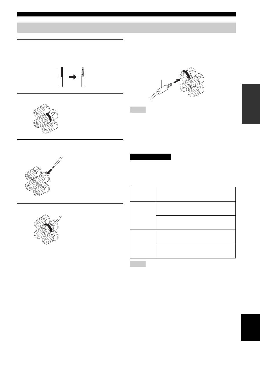
Remove approximately 10 mm (3/8 in) of
insulation from the end of each speaker
cable and twist the exposed wires of the
cable together to prevent short circuits.
2
Unscrew the knob.
3
Insert one bare wire into the hole in the side
of each terminal.
4
Tighten the knob to secure the wire.
■
Connecting the banana plug
(U.S.A., Canada, Australia and General
models only)
First, tighten the knob and then insert the banana plug into
the end of the corresponding terminal.
• One or two speaker sets can be connected to this unit. If you use
only one speaker set, connect it to either the SPEAKERS A or B
terminals.
• Use speakers with the specified impedance shown on the rear
panel of this unit.
■
IMPEDANCE SELECTOR
Do not slide the IMPEDANCE SELECTOR switch while the
power of this unit is turned on, as doing so may damage the unit.
Select the switch position (left or right) according to the
impedance of the speakers in your system.
• The Canada model cannot use two speaker sets (A and B)
simultaneously when the IMPEDANCE SELECTOR switch is
slid to the right position.
• If this unit fails to turn on, the IMPEDANCE SELECTOR
switch may not be fully slid to either position. If this is the case,
slide the switch all the way to either position when the power
supply to this unit is completely cut off.
Connecting speakers
10 mm (3/8 in)
Red: positive (+)
Black: negative (–)
Red: positive (+)
Black: negative (–)
Red: positive (+)
Black: negative (–)
Notes
Switch
position
Impedance level
Right
If you use one set (A or B), the impedance of
each speaker must be 8
Ω
or higher.
If you use two sets (A and B), the impedance
of each speaker must be 16
Ω
or higher.
Left
If you use one set (A or B), the impedance of
each speaker must be 4
Ω
or higher.
If you use two sets (A and B), the impedance
of each speaker must be 8
Ω
or higher.
Notes
Banana plug
CAUTION
