Yamaha RX-497: CONTROLS AND FUNCTIONS
CONTROLS AND FUNCTIONS: Yamaha RX-497
Table of contents
- CAUTION: READ THIS BEFORE OPERATING YOUR UNIT.
- CONTENTS
- FEATURES SUPPLIED ACCESSORIES
- CONTROLS AND FUNCTIONS
- CONTROLS AND FUNCTIONS
- Front panel display
- Rear panel
- Remote control
- CONTROLS AND FUNCTIONS
- Installing batteries in the remote control Using the remote control
- CONNECTIONS
- Connecting speakers
- Connecting the AM and FM antennas
- Connecting the AM loop antenna
- Connecting the power supply cord Turning on and off this unit
- PLAYING AND RECORDING Playing a source
- Adjusting the tonal quality
- Recording a source
- Using the sleep timer
- Muting the sound output
- FM/AM TUNING Automatic tuning
- Manual tuning
- Automatic preset tuning
- Customized automatic preset tuning
- Manual preset tuning
- Selecting preset stations Exchanging preset stations
- RADIO DATA SYSTEM (EUROPE MODEL ONLY) Receiving Radio Data System stations Changing the Radio Data System mode
- PTY SEEK function
- EON function
- ADVANCED SETUP Changing the ADVANCED SETUP menu parameters
- Switching the remote control ID
- ZONE 2 Connecting the Zone 2 components
- Controlling Zone 2
- REMOTE CONTROL FEATURES Control area
- Controlling other components
- Setting remote control codes
- General TROUBLESHOOTING
- Tuner
- Remote control
- SPECIFICATIONS
CONTROLS AND FUNCTIONS
3
INTR
ODUCTION
English
1
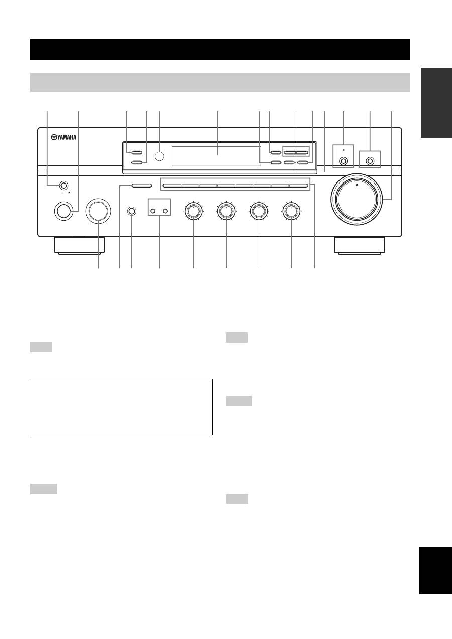
MASTER ON/OFF
Press inward to the ON position to turn on the power of
this unit. Press again to release it outward to the OFF
position to turn off this unit.
See page 14 for details.
Even when this unit is turned off, this unit consumes a small
amount of power to preserve the memory.
2
MAIN ZONE ON/OFF
Turns on Main Zone of this unit or sets it to the standby
mode.
See page 14 for details.
• This switch is operational only when MASTER ON/OFF is
pressed inward to the ON position.
• In the standby mode, this unit consumes a small amount of
power to receive infrared signals from the remote control.
3
ZONE 2 ON/OFF
Turns on Zone 2 or set it to the standby mode. When Zone
2 is turned on, signals are output at the ZONE 2 OUT
jacks.
This switch is operational only when MASTER ON/OFF is
pressed inward to the ON position.
4
ZONE CONTROL
Press to control the input source of Zone 2.
• This button is operational only when Zone 2 is turned on.
• When you press this button, the ZONE 2 indicator flashes in the
front panel display for approximately 5 seconds. Select the
input source of Zone 2 while the indicator is flashing.
• You can select the preset station when TUNER is selected as the
input source of Zone 2.
5
Remote control sensor
Receives infrared signals from the remote control.
Switch the remote control ID between ID1 and ID2 when using
multiple YAMAHA receivers or amplifiers (see pages 29, 30).
6
Front panel display
Shows information about the operational status of this
unit.
CONTROLS AND FUNCTIONS
Front panel
ON/OFF
INPUT
MAIN ZONE
PHONES
BASS
MASTER
SPEAKERS
ON
OFF
MD/TAPE MONITOR
PURE DIRECT
5
5
1
0
1
4
4
2
2
3
3
+
–
VOLUME
l
TUNING
h
ZONE 2 ON/OFF
ZONE CONTROL
FM/AM
EDIT
A/B/C/D/E
1
2
3
4
5
6
7
8
MEMORY
MAN'L/AUTO FM
TUNING MODE
AUTO/MAN'L
B
A
TREBLE
5
5
1
0
1
4
4
2
2
3
3
+
–
BALANCE
5
5
1
0
1
4
4
2
2
3
3
R
L
LOUDNESS
5
7
1
FLAT
6
4
8
2
10
–30dB
3
9
0
12
12
2
8
4
∞
20
20
60
60
26
26
40
40
16
16
-dB
-dB
DISPLAY
5
1
2
4
3
8
7
0 A
6
C
B
9
G
F
E
H
I
J
K
L
M
D
(Europe model)
Note
Memory back-up
The memory back-up circuit prevents the stored data
from being lost. However, the stored data will be lost if
the power cord is disconnected from the AC wall outlet
for more than one week.
Notes
Note
Notes
Note
