De Dietrich MS 24 BIC FF: •
•: De Dietrich MS 24 BIC FF
75
71.06199.02 - EN
INSTALLATION INSTRUCTIONS
20. VISUALISATION OF PARAMETERS ON THE DISPLAY (“INFO” FUNCTION)
Press “
i
” for at least 5 seconds to visualise certain boiler information on the display on the front panel of the boiler.
•
Press buttons (
+/-
) to display the following information:
A00:
current DHW temperature (°C);
A01:
current external temperature (°C) (with external sensor connected);
A02:
modulation current value (100% = 310 mA);
A03:
power range (%) (MAX R);
A04:
heating setpoint temperature (°C) - - If the external sensor is connected, the value of the “
kt
” curve is displayed
(section 26);
A05:
current heating delivery temperature (°C);
A06:
DHW temperature setpoint (°C);
A07:
— — ;
A08:
value (l/minx10) of the DHW flow rate;
A09:
last error that occurred in the boiler.
•
This function remains active for 3 minutes. It is possible to interrupt the “INFO” function in advance by pressing button
(
i
) for at least 5 seconds, or turning off the power to the boiler.
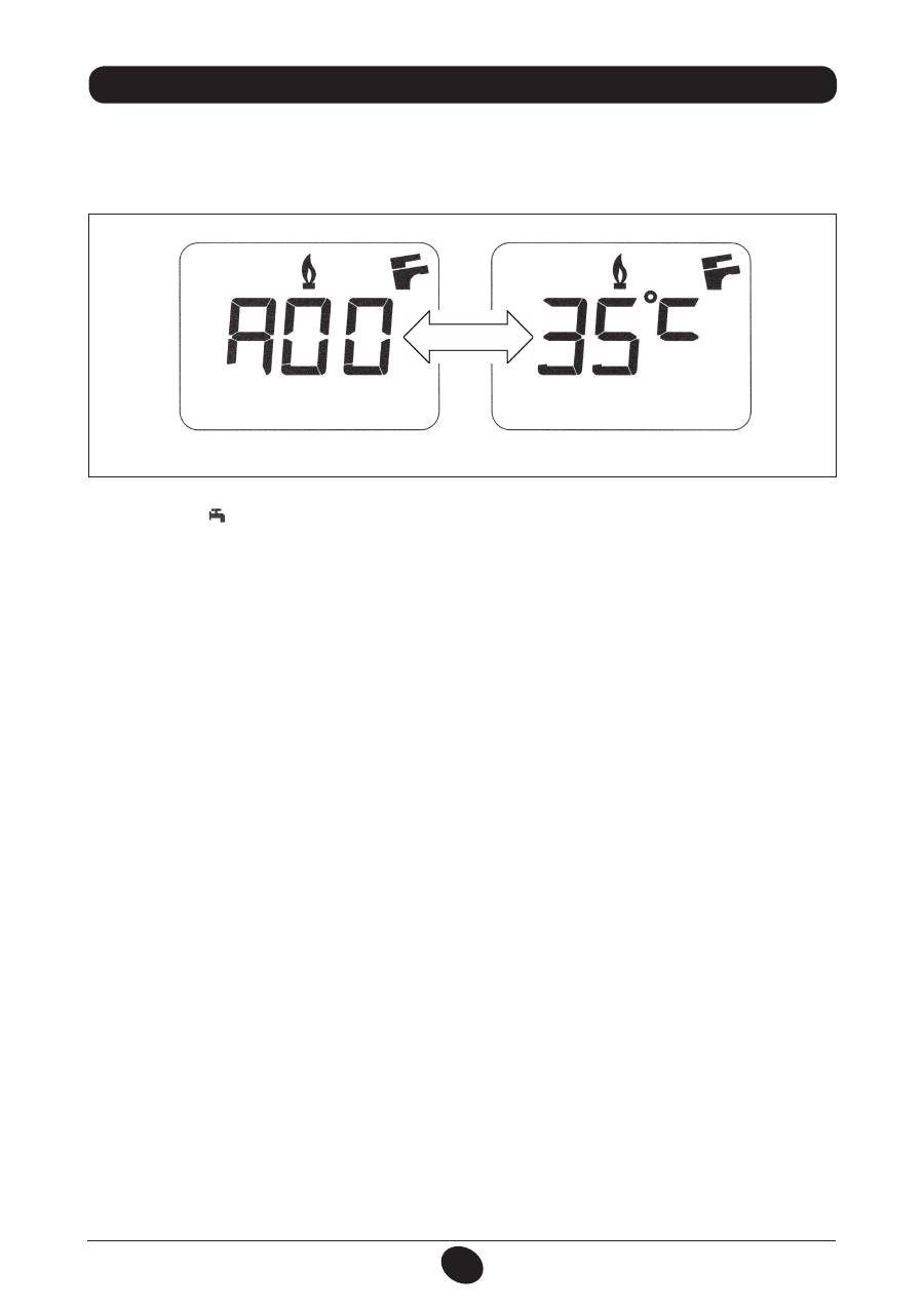
N.B:
when the “INFO” function is enabled, the message “A00”, alternating with the boiler delivery temperature,
is shown on the display (figure 12):
0605_2204 / CG_1808
Figure 12
76
71.06199.02 - EN
INSTALLATION INSTRUCTIONS
Description of parameters
Factory settings
24 BIC FF
24 BIC
F01
Type of boiler
10
= sealed chamber
20
= atmospheric chamber
10
20
F02
Gas used
00
= METHANE
01
= LPG
02
= METHANE (WITH DIAPHRAGM)
02
F03
Hydraulic system
15
F04
Setting programmable relay 1 (See SERVICE instructions)
00
= no associated function
01
= condominium alarm
02
= ambient fan
03
= not used
04
= zone pump controlled by room thermostat (230V)
05
= not used
04
F05
Setting programmable relay 2 (DHW pump)
03
F06
Maximum CH setpoint (°C)
00
= 85°C -
01
= 45°C (function unavailable)
00
F07
DHW inlet priority configuration
00
F08
CH max. output
(0-100%)
100
F09
DHW max. output
(0-100%)
100
F10
Min. heating output
(0-100%)
00
F11
Delay prior to new ignition in CH mode
(00-10 minutes) - 00=10 seconds
03
F12
Diagnostics (See SERVICE Instructions)
--
F13-F14-F15
Factory settings (no change)
00
F16
Anti-legionella function
00
= disabled
55...67
= enabled (setpoint °C)
00
F17
CH pressure sensor selection
00
= hydraulic pressure sensor
01
= hydraulic differential pressure sensor
00
F18
Manufacture information
00
21. PARAMETER SETTINGS
To set the boiler parameters, press (
–
) and (
–
) together and hold down for at least 6 seconds. When the function is
activate, the “
F01
” appears on the display alternating with the value of the parameter shown.
Edit parameters
• Press (
+/–
) to scroll through the parameters;
• Press (
+/–
) to edit each parameter;
• Press
(
)
, to save the changes. “
MEM
” appears on the display;
• Press
(
i
)
,
to exit without saving. “
ESC
” appears on the display.
22. ADJUSTMENT AND SAFETY DEVICES
The boiler has been designed in full compliance with European reference standards and in particular is fitted with the
following:
• Air pressure switch (model 24
BIC FF)
This device only allows the burner to ignite if the exhaust flue duct is in perfect working order.
In the event of one or more of the following faults:
• flue terminal obstructed
• venturi tubes obstructed
• fan blocked
• venturi tube connection - pressure switch tripped
the boiler remains on standby and error code E03 is displayed (see table in section 10).

77
71.06199.02 - EN
INSTALLATION INSTRUCTIONS
• Fumes thermostat (model 24
BIC)
This device has a sensor positioned on the left section of the fumes hood and shuts off the gas flow to the main burner
if the flue is obstructed and/or if there is no draught.
In these conditions the boiler shuts down and displays error code E03 (section 10).
After eliminating the problem, press button ( ), for at least 2 seconds to re-ignite immediately.
It is forbidden to disable this safety device
• Safety thermostat
Thanks to a sensor placed on the CH flow line, this thermostat interrupts the flow of gas to the burner if the water in
the primary circuit overheats. In these conditions, the boiler is blocked and only after the fault has been eliminated can
it be ignited again by pressing ( ), for at least 2 seconds.
It is forbidden to disenable this safety device
• Flame ionization detector
The flame sensing electrode, located on the right-hand side of the burner, guarantees safety of operation in case of gas
failure or incomplete ignition of the burner.
In these conditions, the boiler is blocked after 3 ignition attempts.
Press ( ), for at least 2 seconds to re-establish normal operating conditions.
• Hydraulic pressure switch
This device allows the main burner to be ignited only if system pressure is higher than 0.5 bars.
• Pump overrun for heating circuit
The electronically-controlled pump post-circulation function lasts 180 seconds and is enabled, in the heating mode, if
the ambient thermostat causes the burner to go out.
• Pump overrun for DHW circuit
The electronically-controlled pump post-circulation function lasts 30 seconds and is enabled, in the DHW mode, if the
probe causes the burner to go out.
• Frost protection device (CH and DHW systems)
The electronic boiler management system includes a “frost protection” function for the heating system which, when
delivery temperature falls below 5°C, operates the burner until a delivery temperature of 30°C is reached.
This function is enabled when the boiler is switched on, the gas supply is open and the system is correctly pressurised.
• Water not circulating in primary circuit (pump probably blocked)
If there is insufficient or no water circulating in the primary circuit, the boiler blocks and the error code E25 is shown on
the display (section 10).
• Anti-block pump function
If no heat demand is received for 24 consecutive hours, in the heating mode, the pump will automatically start and
operate for 10 seconds. This function is operative when the boiler is powered.
• Three-way valve anti-blockage function
If no heat demand is received for a period of 24 hours, the three-way valve performs a complete switching cycle. This
function is operative when the boiler is powered.
• Hydraulic safety valve (heating circuit)
This device is set to 3 bar and is used for the heating circuit
.
Connect the safety valve to a drain trap. Do not use it to drain the heating circuit.
N.B.:
domestic hot water is guaranteed even if the NTC sensor develops a fault. In this case, temperature is controlled
by the delivery sensor.
78
71.06199.02 - EN
INSTALLATION INSTRUCTIONS
To measure combustion efficiency and the toxicity of the products of combustion, the boiler is fitted with two dedicated
test points.
One connection point is connected to the exhaust duct and is used to measure combustion efficiency and the toxicity of
the products of combustion.
The other is connected to the air intake circuit and is used to check for the presence of any products of combustion
circu¬lating in installations with co-axial flues.
The following parameters can be measured using the test point connected to the exhaust duct:
• temperature of the products of combustion;
• concentration of oxygen (O
2
) or, alternatively, carbon dioxide (CO
2
);
• concentration of carbon monoxide (CO).
The temperature of the comburent air must be measured on the test point located on the air intake flue by inserting the
measurement sensor by about 3 cm.
N.B.:
to regulate the rated power, see chapter 19 (B1)
For natural draught boiler models, a hole must be made in the exhaust flue at a distance from the boiler equal to twice
the internal diameter of the flue.
The following parameters can be measured through this hole:
• temperature of the products of combustion;
• concentration of oxygen (O
2
) or, alternatively, carbon dioxide (CO
2
);
• concentration of carbon monoxide (CO).
The temperature of the combustion air must be measured close to the point where the air enters the boiler. The hole,
which must be made by the person in charge of the system during commissioning, must be sealed so as to ensure that
the exhaust duct is airtight during normal operation.
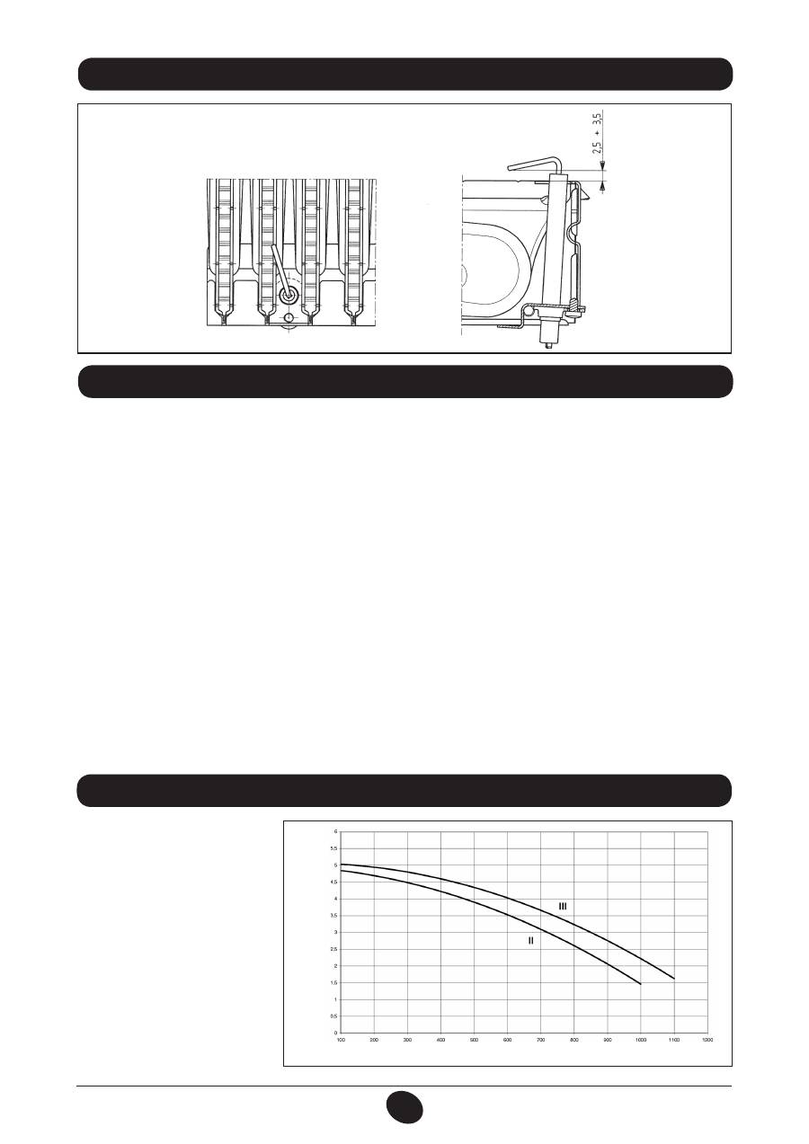
24. CHECKING COMBUSTION PARAMETERS 25. PUMP CAPACITY/ HEAD
A high static head pump (GRUN-
DFOS UPSO 15-50), suitable for
installation on any type of single- or
double-pipe heating system, is used.
The automatic air valve incorporated
in the pump allows quick venting of
the heating system.
Graph 1
FLOW l/h
HEAD mH
2
O
1103_0901
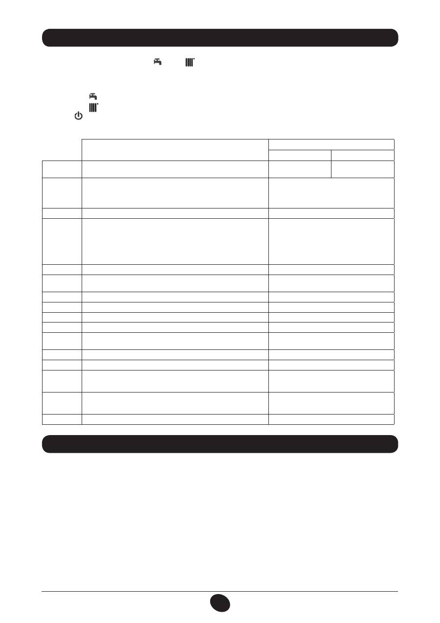
23. POSITIONING THE IGNITION AND FLAME-SENSING ELECTRODE
Figure 13
9912070100
Оглавление
- SOMMAIRE
- 5. DESCRIPTION DES TOUCHES (ÉTÉ – HIVER – CHAUFFAGE SEULEMENT – ARRÊT)
- •
- 27. VASE EXPANSION SANITAIRE (ACCESSOIRE SUR DEMANDE)
- 5. DESCRIZIONE TASTO (Estate - Inverno - Solo riscaldamento - Spento)
- •
- 27. VASO DI ESPANSIONE SANITARIO (ACCESSORIO A RICHIESTA)
- 5. DESCRIPTION OF BUTTON (Summer - Winter - Heating only - Off)
- •
- 27. DHW EXPANSION VESSEL (AVAILABLE ON REQUEST)
- 5. DESCRIPCIÓN DE LA TECLA (Verano - Invierno - Sólo calefacción - Apagado)
- •
- 27. DEPÓSITO DE EXPANSIÓN ACS (ACCESSORIO BAJO PEDIDO)
- 5. ОПИСАНИЕ НА БУТОН (Лято – Зима – Само отопление – Изключен)
- 8. СМЯНА НА ВИДА ГАЗ
- 13. УКАЗАНИЯ ПРЕДИ МОНТАЖА
- 15. РАЗМЕРИ НА КОТЕЛА
- •
- 27. РАЗШИРИТЕЛЕН СЪД ЗА БИТОВИЯ КРЪГ (АКСЕСОАР ПО ЖЕЛАНИЕ)
- SPIS TREŚCI
- 1. OSTRZEŻENIA PRZED ZAINSTALOWANIEM
- 3. ROZRUCH KOTŁA
- 4. REGULACJA TEMPERATURY POKOJOWEJ I CIEPŁEJ WODY UŻYTKOWEJ
- 7. WYŁĄCZENIE KOTŁA 8. ZMIANA GAZU
- 11. INSTRUKCJE ODNOŚNIE KONSERWACJI ZWYKŁEJ
- 12. UWAGI OGÓLNE
- 13. WYMAGANIA INSTALACYJNE
- 15. WYMIARY KOTŁA
- 17. PODŁĄCZENIE ELEKTRYCZNE 18. PODŁĄCZENIE TERMOSTATU POKOJOWEGO
- 19. SPOSÓB ZMIANY RODZAJU GAZU
- •
- 21. USTAWIENIE PARAMETRÓW
- 24. KONTROLA PARAMETRÓW SPALANIA 25. CHARAKTERYSTYKA NATĘŻENIA PRZEPŁYWU/WYSOKOŚCI PODNOSZENIA
- 26. PODŁĄCZENIE CZUJNIKA ZEWNĘTRZNEGO
- 34. SCHEMAT FUNKCJONALNY OBWODÓW
- 35. SCHEMAT POŁACZEŃ ELEKTRYCZNYCH
- 36. CHARAKTERYSTYKA TECHNICZNA
- CUPRINS
- 1. AVERTISMENTE ANTERIOARE INSTALĂRII
- 3. PUNEREA ÎN FUNCŢIUNE A CENTRALEI TERMICE
- 4. REGLAREA TEMPERATURII AMBIANTE ŞI A TEMPERATURII APEI MENAJERE
- 7. OPRIREA CENTRALEI TERMICE 8. SCHIMBAREA TIPULUI DE GAZ
- 10. INTRAREA ÎN FUNCŢIUNE A DISPOZITIVELOR DE SIGURANŢA
- 12. AVERTISMENTE GENERALE
- 13. AVERTISMENTE ANTERIOARE INSTALĂRII 13. INSTALLAZIONE DELLA CALDAIA 14. INSTALAREA CENTRALEI TERMICE
- 14. DIMENSIONI CALDAIA 15. DIMENSIUNILE CENTRALEI TERMICE
- 17. CONECTAREA LA REŢEAUA ELECTRICĂ 18. CONECTAREA TERMOSTATULUI AMBIENTAL
- 19. MODALITĂŢI DE SCHIMBARE A TIPULUI DE GAZ
- 20. VIZUALIZAREA PARAMETRILOR PE AFIŞAJ (FUNCŢIE “INFO”)
- 21. SETAREA PARAMETRILOR
- 24. VERIFICAREA PARAMETRILOR DE COMBUSTIE 25. PERFORMANŢE DEBIT/ÎNĂLŢIME DE POMPARE
- 26. CONECTAREA SONDEI EXTERNE
- 34. DIAGRAMĂ FUNCŢIONALĂ CIRCUITE
- 35. DIAGRAMĂ CUPLARE CONECTORI
- 36. CARACTERISTICI TEHNICE
- ΠΕΡΙΕΧΟΜΕΝΑ
- 1. ΟΔΗΓΙΕΣ ΠΡΙΝ ΤΗΝ ΕΓΚΑΤΑΣΤΑΣΗ
- 3. ΘΕΣΗ ΣΕ ΛΕΙΤΟΥΡΓΙΑ ΤΟΥ ΛΕΒΗΤΑ
- 4. ΡΥΘΜΙΣΗ ΤΗΣ ΘΕΡΜΟΚΡΑΣΙΑΣ ΠΕΡΙΒΑΛΛΟΝΤΟΣ ΚΑΙ ΤΟΥ ΝΕΡΟΥ ΟΙΚΙΑΚΗΣ ΧΡΗΣΗΣ
- 7. ΣΒΗΣΙΜΟ ΤΟΥ ΛΕΒΗΤΑ 8. ΑΛΛΑΓΗ ΑΕΡΙΟΥ
- 10. ΕΝΔΕΙΞΕΙΣ-ΕΠΕΜΒΑΣΗ ΣΥΣΤΗΜΑΤΩΝ ΑΣΦΑΛΕΙΑΣ
- 12. ΓΕΝΙΚΕΣ ΠΛΗΡΟΦΟΡΙΕΣ
- 13. ΟΔΗΓΙΕΣ ΠΡΙΝ ΤΗΝ ΕΓΚΑΤΑΣΤΑΣΗ 13. INSTALLAZIONE DELLA CALDAIA 14. ΕΓΚΑΤΑΣΤΑΣΗ ΤΟΥ ΛΕΒΗΤΑ
- 14. DIMENSIONI CALDAIA 15. ΔΙΑΣΤΑΣΕΙΣ ΛΕΒΗΤΑ
- 17. ΗΛΕΚΤΡΙΚΗ ΣΥΝΔΕΣΗ 18. ΣΥΝΔΕΣΗ ΤΟΥ ΘΕΡΜΟΣΤΑΤΗ ΔΩΜΑΤΙΟΥ
- 19. ΤΡΟΠΟΣ ΑΛΛΑΓΗΣ ΑΕΡΙΟΥ
- 20. ΑΠΕΙΚΟΝΙΣΗ ΠΑΡΑΜΕΤΡΩΝ ΣΤΗΝ ΟΘΟΝΗ (ΛΕΙΤΟΥΡΓΙΑ «INFO»)
- 21. ΡΥΘΜΙΣΗ ΠΑΡΑΜΕΤΡΩΝ
- 24. ΕΛΕΓΧΟΣ ΠΑΡΑΜΕΤΡΩΝ ΚΑΥΣΗΣ 25. ΧΑΡΑΚΤΗΡΙΣΤΙΚΑ ΠΑΡΟΧΗΣ / ΜΑΝΟΜΕΤΡΙΚΟΥ ΥΨΟΥΣ ΣΤΗΝ ΠΛΑΚΑ
- 26. ΣΥΝΔΕΣΗ ΤΟΥ ΕΞΩΤΕΡΙΚΟΥ ΑΙΣΘΗΤΗΡΑ
- 34. ΛΕΙΤΟΥΡΓΙΚΟ ΣΧΕΔΙΟ ΚΥΚΛΩΜΑΤΩΝ
- 35. ΣΧΕΔΙΟ ΣΥΝΔΕΣΗΣ ΣΥΝΔΕΣΜΩΝ
- 36. ТЕХНИЧЕСКИ ХАРАКТЕРИСТИКИ
- 5. ОПИСАНИЕ КНОПКИ (Лето – Зима – Только Отопление – Выключено)
- •
- 27. РАСШИРИТЕЛЬНЫЙ БАК ГВС (ПРИНАДЛЕЖНОСТЬ ПО ЗАКАЗУ)
- 5. 锅炉运行模式选择
- 错误信息及故障表
- 27. 热水膨胀罐(可额外订购的配件)
