De Dietrich MS 24 BIC FF: 27. VASO DI ESPANSIONE SANITARIO (ACCESSORIO A RICHIESTA)
27. VASO DI ESPANSIONE SANITARIO (ACCESSORIO A RICHIESTA): De Dietrich MS 24 BIC FF
50
71.06199.02 - IT
ISTRUZIONI DESTINATE ALL’INSTALLATORE
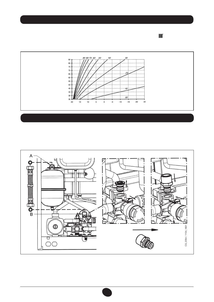
26. COLLEGAMENTO DELLA SONDA ESTERNA
Sul cablaggio di cavi che escono dal cruscotto, ci sono due cavetti di colore ROSSO dotati di copri-faston di testa.
Collegare la sonda esterna ai capi di questi due cavetti.
Con sonda esterna collegata è possibile cambiare la curva “
kt
” (Grafico 2) agendo sui tasti
+/-
.
NOTA : Nel caso di installazione in una unità abitativa media (buon isolamento perimetrale e impianto a radiatori) è consi-
gliabile impostare la curva climatica “
kt
” al valore di “25”.
TM
= Range temperature mandata
Te
= temperatura esterna
Grafico 2
TM
Te
curve “kt”
1012_0501
Kit vaso d’espansione sanitario costituito da:
- 1 vaso espansione in acciaio inox;
- 1 supporto per vaso espansione;
- 1 nipplo G1/2”;
- 1 controdado;
- 1 tubo di collegamento flessibile.
27. VASO DI ESPANSIONE SANITARIO (ACCESSORIO A RICHIESTA)
Collegare il tubo flessibile (fornito come accessorio nel kit vaso espansione) sui due raccordi A e B come illustrato in figura.
Il montaggio del vaso di espansione sanitario è consigliato nei casi in cui:
- la pressione dell’acquedotto o del sistema di sollevamento idrico è tale che si rende necessaria l’installazione di un
riduttore di pressione (pressione superiore a 4 bar)
- sulla rete acqua fredda è installata una valvola di non ritorno
- lo sviluppo della rete acqua fredda è insufficiente per l’espansione dell’acqua contenuta nei bollitore ed è necessario
prevedere l’utilizzo del vaso espansione sanitario.
51
71.06199.02 - IT
ISTRUZIONI DESTINATE ALL’INSTALLATORE
Allo scopo di assicurare un’efficienza ottimale della caldaia è necessario effettuare annualmente i seguenti controlli:
• verifica dell’aspetto e della tenuta delle guarnizioni del circuito gas e del circuito di combustione;
• verifica dello stato e della corretta posizione degli elettrodi di accensione e rivelazione di fiamma;
• verifica dello stato del bruciatore ed il suo corretto fissaggio;
• verifica delle eventuali impurità presenti all’interno della camera di combustione.
Utilizzare allo scopo un aspirapolvere per la pulizia;
• verifica della corretta taratura della valvola gas;
• verifica della pressione dell’impianto di riscaldamento;
• verifica della pressione del vaso espansione;
• verifica che il ventilatore funzioni correttamente;
• verifica che i condotti di scarico e aspirazione non siano ostruiti;
• verifica stato anodo bollitore.
AVVERTENZE
Prima di effettuare qualsiasi intervento, assicurarsi che la caldaia non sia alimentata elettricamente.
Terminate le operazioni di manutenzione, riportare le manopole e/o i parametri di funzionamento della caldaia
nelle posizioni originali.
28. MANUTENZIONE ANNUALE
RACCOMANDAZIONE
Per un efficace funzionamento del vaso di espansione, la pressione dell’acquedotto deve essere inferiore a 4 bar. In caso
contrario, installare un riduttore di pressione. Il riduttore di pressione deve essere regolato in modo da avere una pressione
di alimentazione dell’acqua inferiore a 4 bar.
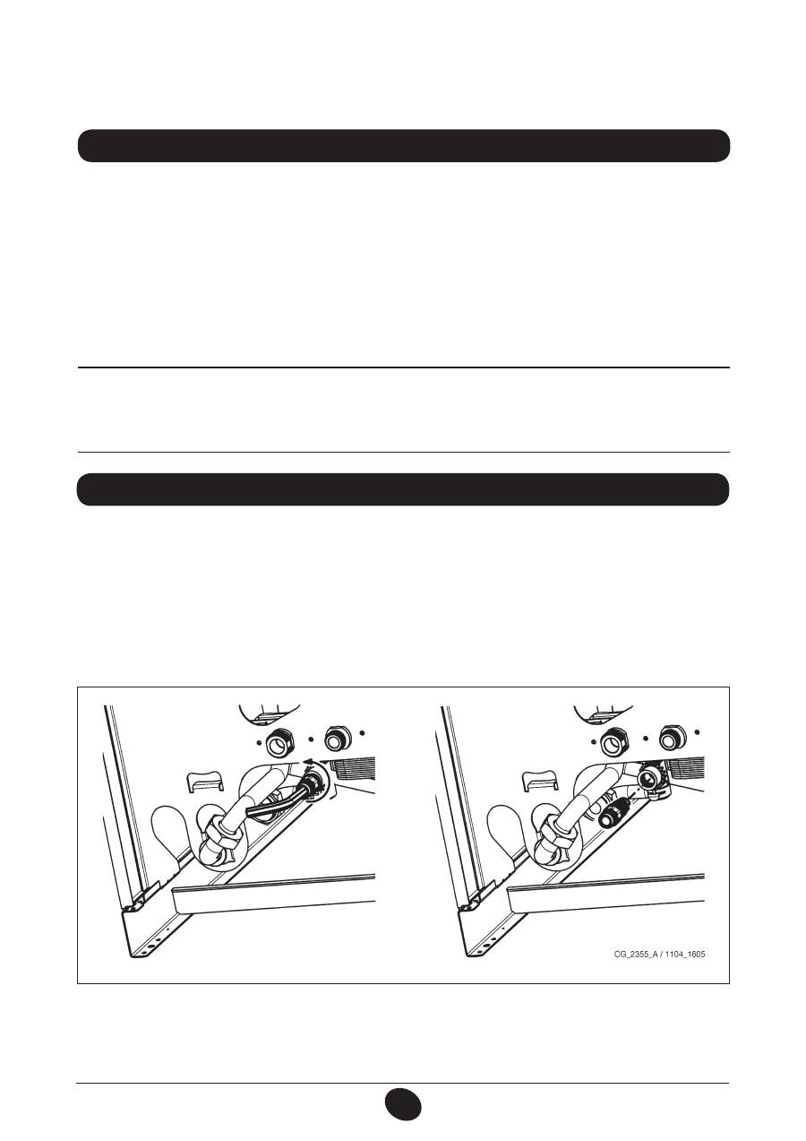
SVUOTAMENTO CIRCUITO CALDAIA
Lo svuotamento della caldaia può essere effettuato tramite il rubinetto posto nel gruppo idraulico.
Per svuotare la caldaia con il rubinetto porta-gomma posto sul fondo della caldaia procedere come di seguito descritto
(fig. 14):
- chiudere i rubinetti di intercettazione della caldaia;
- aprire il rubinetto porta-gomma utilizzando una chiave esagonale da 8 mm;
- svuotare la caldaia;
- chiudere il rubinetto porta-gomma utilizzando la chiave esagonale da 8mm.
29. SVUOTAMENTO DEL CIRCUITO CALDAIA E DEL BOLLITORE
Figura 14

52
71.06199.02 - IT
ISTRUZIONI DESTINATE ALL’INSTALLATORE
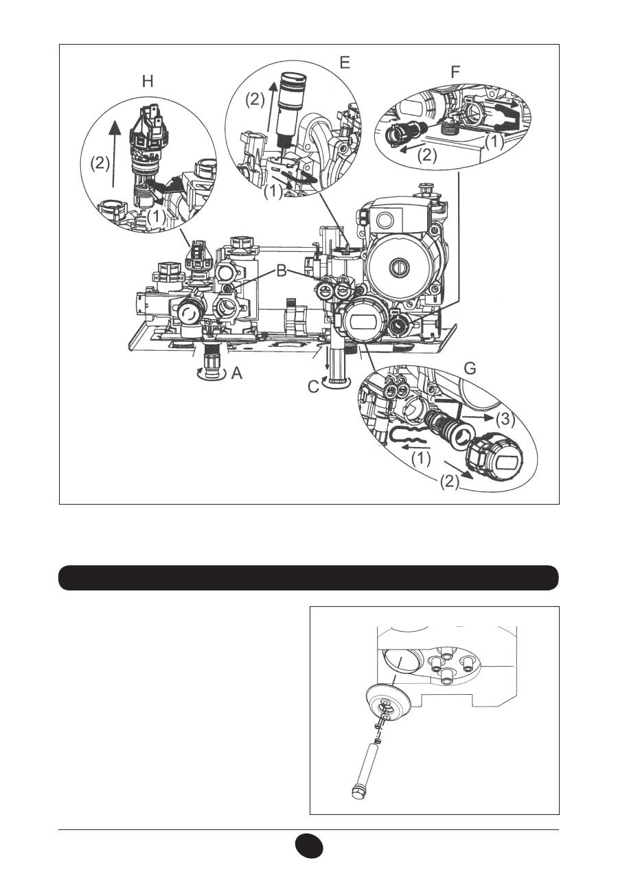
I filtri dell’acqua sanitaria e del circuito di riscaldamento sono alloggiati all’interno di apposite cartucce estraibili. La car-
tuccia del circuito di riscaldamento è posizionata sul ritorno del riscaldamento (figura 15F). Per la pulizia dei filtri agendo
come di seguito riportato:
• togliere l’alimentazione elettrica alla caldaia;
• chiudere il rubinetto dell’acqua d’ingresso sanitario;
• svuotare l’acqua contenuta nel circuito di riscaldamento aprendo il rubinetto A di figura 15.
• rimuovere la clip (1-F) del filtro come illustrato in figura ed estrarre la cartuccia (2-F) contenente il filtro avendo cura di
non esercitare una forza eccessiva;
• per estrarre la cartuccia del filtro di riscaldamento è necessario prima rimuovere il motore della valvola 3 vie (1-2G -
figura 15);
• eliminare dal filtro eventuali impurità e depositi;
• riposizionare il filtro all’interno della cartuccia e inserire nuovamente la stessa nella propria sede assicurandola con la
propria clip.
AVVERTENZA
In caso di sostituzione e/o pulizia degli anelli “OR” del gruppo idraulico non utilizzare come lubrificanti olii o grassi ma
esclusivamente Molykote 111.
30. PULIZIA DEI FILTRI
Per le operazioni di pulizia è necessario:
• Chiudere il rubinetto d’entrata dell’acqua sanitaria
• Svuotare dall’acqua il circuito sanitario mediante un rubinetto utilizzatore
• Chiudere il rubinetto d’uscita dell’acqua sanitaria
• Rimuovere la clip 1E di figura 15
• Togliere il filtro (2E figura 15).
Smontare lo scambiatore acqua-acqua, come descritto al paragrafo successivo, e pulirlo isolatamente.
Per la pulizia dello scambiatore e/o del circuito sanitario è consigliabile l’utilizzo di Cillit FFW-AL o Benckiser HF-AL.
31. PULIZIA DAL CALCARE DEL CIRCUITO SANITARIO
Lo scambiatore acqua-acqua, del tipo a piastre in acciaio inox, può essere facilmente smon tato con l’utilizzo di una chiave
esagonale M4 procedendo come di seguito descritto:
• svuotare l’impianto, se possibile limitatamente alla caldaia,
mediante l’apposito rubinetto di scarico
;
• svuotare l’acqua contenuta nel circuito sanitario;
• togliere le due viti, visibili frontalmente, di fissaggio dello scambiatore acqua-acqua e sfilarlo dalla sua sede (fig. 15B).
32. SMONTAGGIO DELLO SCAMBIATORE ACQUA-ACQUA
SVUOTAMENTO BOLLITORE
Lo svuotamento dell’acqua contenuta nel bollitore può essere effettuato procedendo come di seguito descritto:
- chiudere il rubinetto entrata acqua sanitario;
- aprire un rubinetto utilizzatore;
- aprire l’apposito rubinetto di scarico (Fig. 2-B);
- svitare leggermente il dado sul tubo di uscita dell’acqua sanitaria presente sul fondo del bollitore.
53
71.06199.02 - IT
ISTRUZIONI DESTINATE ALL’INSTALLATORE
Verificare annualmente lo stato dell’anodo protettivo in ma-
gnesio (prima di procedere svuotare il circuito del bollitore
utilizzando l’apposito rubinetto di scarico).
Per smontare il gruppo anodo togliere la clip di fissaggio
della sonda bollitore, sfilare la stessa e con una chiave fissa
da 27 mm (A) allentare il dado del supporto dell’anodo.
33. SMONTAGGIO ANODO BOLLITORE
CG_2341 / 1103_2303
A
AVVERTENZA
Prestare la massima attenzione durante lo smontaggio delle singole parti del gruppo idraulico.
Non utilizzare utensili appuntiti, non esercitare una forza eccessiva nel rimuovere le clip di fissaggio.
CG_2326 / 1103_0401
Figura 15
54
71.06199.02 - IT
ISTRUZIONI DESTINATE ALL’INSTALLATORE
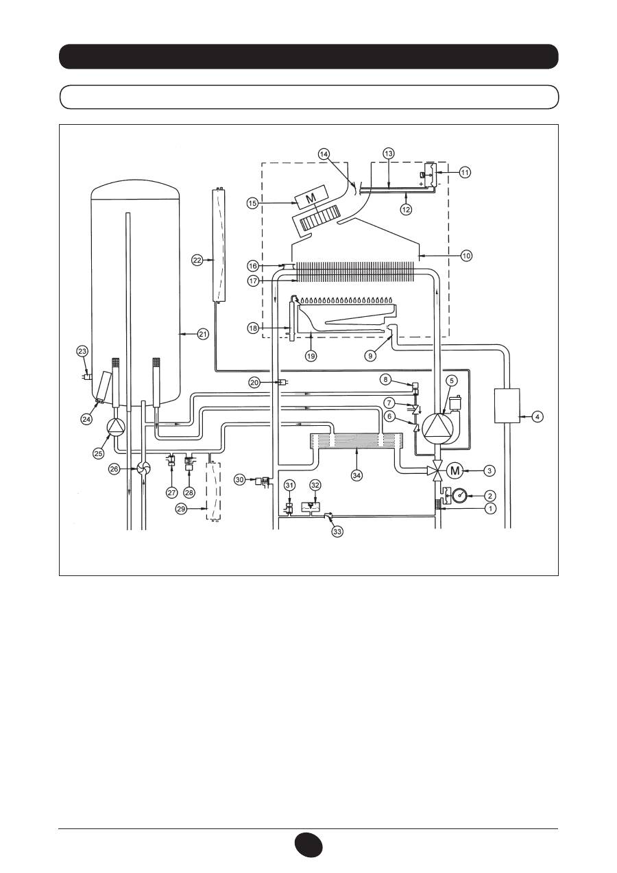
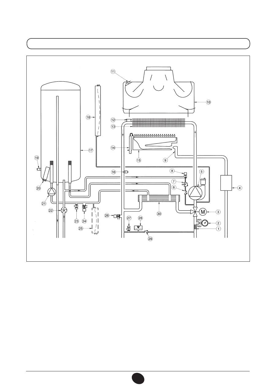
34. SCHEMA FUNZIONALE CIRCUITI
24 BIC FF
Legenda:
1
filtro riscaldamento
2
manometro
3
valvola 3 vie motorizzata
4
valvola gas con diaframma gas
5
pompa circuito riscaldamento con degasatore
6
valvola di non ritorno
7
disconnettore
8
rubinetto di caricamento caldaia
9
rampa gas con ugelli
10
convogliatore fumi
11
pressostato aria
12
presa di pressione negativa
13
presa di pressione positiva
14
venturi
15
ventilatore
16
termostato di sicurezza
17
scambiatore acqua-fumi
18
elettrodo accensione/ rilevazione fiamma
19
bruciatore
20
sonda NTC riscaldamento
21
bollitore
22
vaso espansione circuito riscaldamento
23
sonda NTC sanitario
24
anodo sacrificale
25
pompa circuito sanitario
26
sensore di precedenza sanitario
27
rubinetto di scarico bollitore
28
valvola di sicurezza circuito sanitario
29
vaso espansione circuito sanitario (accessorio)
30
valvola di sicurezza di caldaia
31
rubinetto di scarico caldaia
32
pressostato idraulico
33
valvola di ritegno su by-pass automatico
34
scambiatore a piastre
Figura 16
Mandata
riscaldamento
Uscita
sanitario
Gas
Entrata
sanitario
Ritorno
riscaldamento
CG_2337 / 1104_0402
55
71.06199.02 - IT
ISTRUZIONI DESTINATE ALL’INSTALLATORE
24 BIC
Legenda:
1
filtro riscaldamento
2
manometro
3
valvola 3 vie motorizzata
4
valvola gas con diaframma gas
5
pompa circuito riscaldamento con degasatore
6
valvola di non ritorno
7
disconnettore
8
rubinetto di caricamento caldaia
9
rampa gas con ugelli
10
convogliatore fumi
11
termostato fumi
12
termostato di sicurezza
13
scambiatore acqua-fumi
14
elettrodo accensione/ rilevazione fiamma
15
bruciatore
16
sonda NTC riscaldamento
17
bollitore
18
vaso espansione circuito riscaldamento
19
sonda NTC sanitario
20
anodo sacrificale
21
pompa circuito sanitario
22
sensore di precedenza sanitario
23
rubinetto di scarico bollitore
24
valvola di sicurezza circuito sanitario
25
vaso espansione circuito sanitario (accessorio)
26
valvola di sicurezza di caldaia
27
rubinetto di scarico caldaia
28
pressostato idraulico
29
valvola di ritegno su by-pass automatico
30
scambiatore a piastre
Figura 17
Mandata
riscaldamento
Uscita
sanitario
Gas
Entrata
sanitario
Ritorno
riscaldamento
CG_2338 / 1104_0403
56
71.06199.02 - IT
ISTRUZIONI DESTINATE ALL’INSTALLATORE
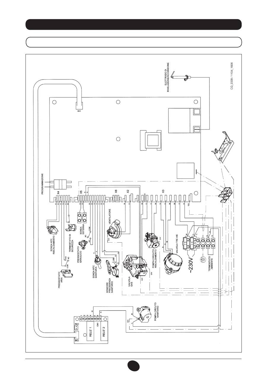
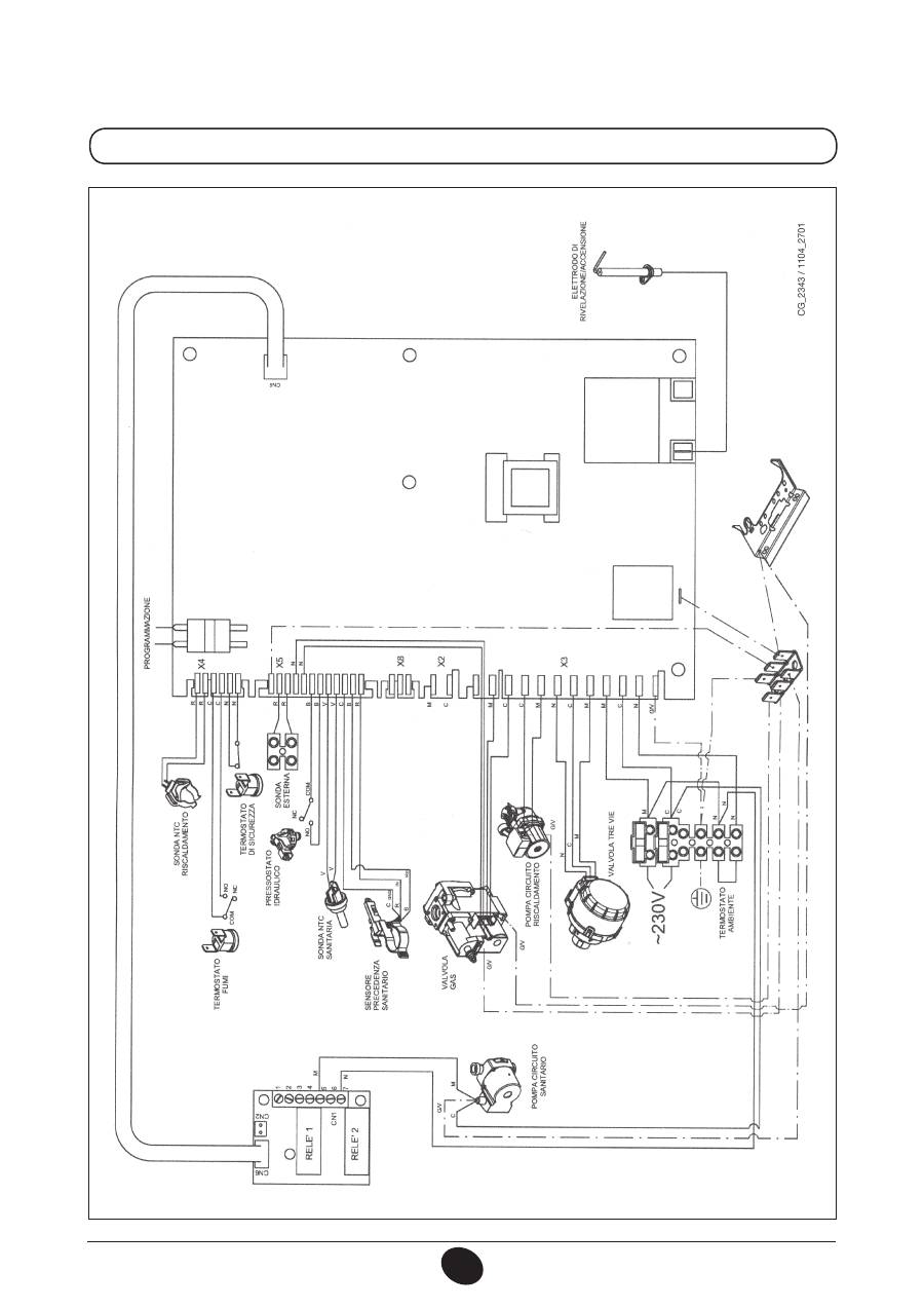
35. SCHEMA COLLEGAMENTO CONNETTORI
24 BIC FF
Color
e cavetti
C
= Celeste
M
= Marr
one
N
= Ner
o
R
= Rosso
G/V
= Giallo/V
er
de
B
= Bianco
V
= V
er
de
57
71.06199.02 - IT
ISTRUZIONI DESTINATE ALL’INSTALLATORE
24 BIC
Color
e cavetti
C
= Celeste
M
= Marr
one
N
= Ner
o
R
= Rosso
G/V
= Giallo/V
er
de
B
= Bianco
V
= V
er
de

58
71.06199.02 - IT
ISTRUZIONI DESTINATE ALL’INSTALLATORE
36. CARATTERISTICHE TECNICHE
DE DIETRICH
,
nella costante azione di miglioramento dei prodotti, si riserva la possibilità di modificare i dati espressi in questa documentazione
in qualsiasi momento e senza preavviso. La presente documentazione è un supporto informativo e non considerabile come contratto nei
confronti di terzi.
Modello MS
24 BIC FF
24 BIC
Categoria
II
2H
3P
II
2H
3P
Portata termica nominale
kW
25,8
25,8
Portata termica ridotta
kW
11,9
11,9
Potenza termica nominale
kW
24
23,3
kcal/h
20.600
20.000
Potenza termica ridotta
kW
10,4
10,4
kcal/h
8.900
8.900
Rendimento secondo la direttiva 92/42/CEE
—
★★★
★★
Pressione massima acqua circuito termico
bar
3
3
Capacità vaso espansione
l
7,5
7,5
Pressione del vaso d’espansione
bar
1
1
Capacità bollitore
l
42
42
Pressione massima acqua circuito sanitario
bar
7
7
Pressione minima dinamica acqua circuito sanitario
bar
0,15
0,15
Portata minima acqua sanitaria
l/min
2,0
2,0
Produzione acqua sanitaria con ∆T=25 °C
l/min
13,3
13,3
Produzione acqua sanitaria con ∆T=35 °C
l/min
9
9,5
Portata specifica (*)
l/min
17,7
17,7
Range temperatura circuito di riscaldamento
°C
30/85
30/85
Range temperatura acqua sanitaria
°C
35/60
35/60
Tipo
—
C12-C32-C42-C52-C82-B22
B
11BS
Diametro condotto di scarico concentrico
mm
60
-
Diametro condotto di aspirazione concentrico
mm
100
-
Diametro condotto di scarico sdoppiato
mm
80
-
Diametro condotto di aspirazione sdoppiato
mm
80
-
Diametro condotto di scarico
mm
-
125
Portata massica fumi max
kg/s
0,021
0,021
Portata massica fumi min
kg/s
0,021
0,019
Temperatura fumi max
°C
135
110
Temperatura fumi min
°C
108
85
Classe NOx
—
3
3
Tipo di gas
—
G20
G20
—
G31
G31
Pressione di alimentazione gas metano
mbar
20
20
Pressione di alimentazione gas propano
mbar
37
37
Tensione di alimentazione elettrica
V
230
230
Frequenza di alimentazione elettrica
Hz
50
50
Potenza elettrica nominale
W
135
80
Peso netto
kg
61
51
Dimensioni
altezza
mm
950
950
larghezza
mm
600
600
profondità
mm
466
466
Grado di protezione contro l’umidità e la penetrazione dell’acqua (**)
IP X5D
IP X5D
(*)
secondo
EN 625 - (**)
secondo
EN 60529
59
71.06199.02 - EN
OPERATING INSTRUCTIONS
Dear Customer,
We are confident your new boiler will meet all your requirements.
All
De Dietrich
products have been designed to give you what you are looking for: good performance
combined with simple and rational use.
Please do not put away this booklet without reading it first as it contains some useful information
which will help you to operate your boiler correctly and efficiently.
Do not leave any packaging (plastic bags, polystyrene, etc.) within the reach of children as they are a potential
source of danger.
1.
Instructions prior to installation
60
2.
Instructions prior to commissioning
60
3.
Commissioning the boiler
61
4.
Adjusting room and DHW temperatures
62
5.
Description of button (
) (Summer - Winter - Heating only - Off)
62
6.
Filling the system
62
7.
Turning off the boiler
63
8.
Gas conversion
63
9.
Prolonged shutdown. Frost protection
63
10.
Troubleshooting 64
11.
Routine maintenance instructions
64
12.
General information
65
13.
Instructions prior to installation
66
14.
Installing the boiler
66
15.
Dimensions of boiler
68
16.
Installating the flue and air ducts
68
17.
Electrical connections
72
18.
Connecting the room thermostat
72
19.
Gas conversion
73
20.
Visualisation of parameters on the display (“info” function)
75
21.
Parameter settings
76
22.
Adjustment and safety devices
76
23.
Positioning the ignition and flame-sensing electrode
78
24.
Checking combustion parameters
78
25.
Pump capacity/head
78
26.
Connecting the external sensor
79
27.
DHW expansion vessel (available on request)
79
28.
Annual service
80
29.
Draining the boiler circuit and the storage boiler
80
30.
Cleaning the filters
81
31.
Removing scale from the DHW circuit
81
32.
Dismounting the water-water heat exchanger
81
33.
Disassembling the boiler anode
82
34.
Functional circuit diagram
83
35.
Wiring diagram
85
36.
Technical specifications
87
CONTENTS
INSTRUCTIONS FOR USERS
INSTRUCTIONS FOR FITTERS
De Dietrich
declares that these models of boiler bear the CE mark in compliance
with the basic requirements of the following Directives:
- Gas directive 2009/142/EC
- Efficiency Directive 92/42/EEC
- Electromagnetic Compatibility Directive 2004/108/EC
- Low Voltage Directive 2006/95/EC

60
71.06199.02 - EN
OPERATING INSTRUCTIONS
This boiler has been designed to heat water to a temperature lower than boiling point at atmospheric pressure. It must
be connected to a central heating system and to a domestic hot water supply system according to its performance and
power output.
Before having the boiler installed by a qualified fitter, make sure the following operations are performed:
a) Make sure that the boiler is adjusted to use the type of gas delivered by the gas supply. To do this, check the markings
on the packaging and the rating plate on the appliance.
b) Make sure that the flue terminal draft is appropriate, that the terminal is not obstructed and that no exhaust gases
from other appliances are expelled through the same flue duct, unless the latter has been specially designed to collect
exhaust gas from more than one appliance, in compliance with current laws and regulations.
c) Make sure that, if the boiler is connected to existing flue ducts, these have been thoroughly cleaned as residual products
of combustion may detach from the walls during operation and obstruct the flow of fumes.
d) To ensure correct operation and maintain the warranty, observe the following precautions:
1. DHW circuit:
1.1.
If the water is harder than 20 °F (1 °F = 10 mg calcium carbonate per litre of water), install a polyphosphate
dispenser or an equivalent treatment system, compliant with current regulations.
1.2.
Thoroughly flush the system after installation of the appliance and before use.
1.3.
The materials used for the product’s DHW circuit comply with Directive 98/83/CE.
2. Heating circuit
2.1. new system
Before proceeding with installation of the boiler, the system must be cleaned and flushed to eliminate residual
thread-cutting swarf, solder and any solvents, using suitable proprietary products. To avoid damaging metal, plastic
and rubber parts, only use neutral cleaners, i.e. non-acid and non alkaline. Recommended cleaning products are:
SENTINEL X300 or X400 and FERNOX Regenerator for heating circuits. Use these products in strict compliance
with the manufacturers’ instructions.
2.2. existing system:
Before installing the boiler, drain the system and clean it to remove sludge and contaminants, using suitable
proprietary products as described in section 2.1.
To avoid damaging metal, plastic and rubber parts, use only neutral cleaners, i.e. non-acid and non-alkaline such as
SENTINEL X100 and FERNOX Protector for heating circuits. Use these products in strict compliance with the
manufacturers’ instructions.
Remember that the presence of foreign bodies in the heating system can adversely affect boiler operation (e.g.
overheating and excessive noise of the heat exchanger).
Failure to observe the above will render the warranty null and void
.
1. INSTRUCTIONS PRIOR TO INSTALLATION
Initial lighting of the boiler must be carried out by an authorised Service Engineer who must first ensure that:
a) the rated data correspond to the supply (electricity, water and gas) data;
b) the installation complies with current laws and regulations;
c) the appliance is correctly connected to the power supply and earthed. Failure to observe the above will render the
guarantee null and void.
Prior to commissioning, remove the protective plastic coating from the boiler. Do not use any tools or abrasive detergents
to do this as you may damage the painted surfaces.
The appliance is not intended to be used by persons (including children) with reduced physical, sensory or mental
capacities, or who lack experience or knowledge, unless, through the mediation of a person responsible for their
safety, they have had the benefit of supervision or of instructions on the use of the appliance.
2. INSTRUCTIONS PRIOR TO COMMISSIONING
61
71.06199.02 - EN
OPERATING INSTRUCTIONS
To light the boiler correctly, proceed as follows:
1) power the boiler
2) open the gas tap;
3) press the button (
)
and switch the boiler to Summer ( ), Winter (
) or heating only (
);
4) press the heating circuit (
+/-
) and domestic hot water circuit (
) temperature adjustment buttons ( ) in order to ignite
the main burner.
When the boiler is lit, the symbol ( ) will appear on the display.
In the Summer position ( ) the main burner will only ignite if a DHW tap is opened.
WARNING
During initial ignition, the burner may not ignite (causing the boiler to shut down) until any air in the gas pipes is vented. In
this case, repeat the ignition procedure until gas reaches the burner. Press button ( ), for at least 2 seconds.
3. COMMISSIONING THE BOILER
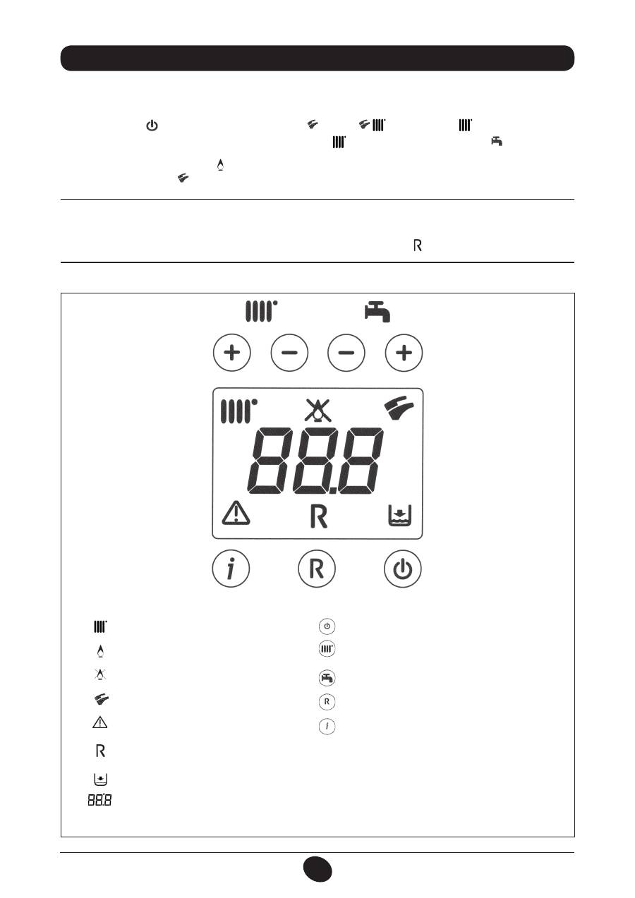
Operation in the heating mode
Flame present (burner on)
No flame (ignition failure)
Operation in the DHW mode
Generic fault
No water (Low system pressure)
Numerical signal (Temperature, fault code, etc.)
RESET
BUTTON KEY
Figure 1
SYMBOL KEY
On / Off / Summer / Winter / heating only
(
+/-
) : CH temperature adjustment
(
+/-
) : DHW temperature adjustment
Reset
Information
0805_2302 / C
G_2072
Оглавление
- SOMMAIRE
- 5. DESCRIPTION DES TOUCHES (ÉTÉ – HIVER – CHAUFFAGE SEULEMENT – ARRÊT)
- •
- 27. VASE EXPANSION SANITAIRE (ACCESSOIRE SUR DEMANDE)
- 5. DESCRIZIONE TASTO (Estate - Inverno - Solo riscaldamento - Spento)
- •
- 27. VASO DI ESPANSIONE SANITARIO (ACCESSORIO A RICHIESTA)
- 5. DESCRIPTION OF BUTTON (Summer - Winter - Heating only - Off)
- •
- 27. DHW EXPANSION VESSEL (AVAILABLE ON REQUEST)
- 5. DESCRIPCIÓN DE LA TECLA (Verano - Invierno - Sólo calefacción - Apagado)
- •
- 27. DEPÓSITO DE EXPANSIÓN ACS (ACCESSORIO BAJO PEDIDO)
- 5. ОПИСАНИЕ НА БУТОН (Лято – Зима – Само отопление – Изключен)
- 8. СМЯНА НА ВИДА ГАЗ
- 13. УКАЗАНИЯ ПРЕДИ МОНТАЖА
- 15. РАЗМЕРИ НА КОТЕЛА
- •
- 27. РАЗШИРИТЕЛЕН СЪД ЗА БИТОВИЯ КРЪГ (АКСЕСОАР ПО ЖЕЛАНИЕ)
- SPIS TREŚCI
- 1. OSTRZEŻENIA PRZED ZAINSTALOWANIEM
- 3. ROZRUCH KOTŁA
- 4. REGULACJA TEMPERATURY POKOJOWEJ I CIEPŁEJ WODY UŻYTKOWEJ
- 7. WYŁĄCZENIE KOTŁA 8. ZMIANA GAZU
- 11. INSTRUKCJE ODNOŚNIE KONSERWACJI ZWYKŁEJ
- 12. UWAGI OGÓLNE
- 13. WYMAGANIA INSTALACYJNE
- 15. WYMIARY KOTŁA
- 17. PODŁĄCZENIE ELEKTRYCZNE 18. PODŁĄCZENIE TERMOSTATU POKOJOWEGO
- 19. SPOSÓB ZMIANY RODZAJU GAZU
- •
- 21. USTAWIENIE PARAMETRÓW
- 24. KONTROLA PARAMETRÓW SPALANIA 25. CHARAKTERYSTYKA NATĘŻENIA PRZEPŁYWU/WYSOKOŚCI PODNOSZENIA
- 26. PODŁĄCZENIE CZUJNIKA ZEWNĘTRZNEGO
- 34. SCHEMAT FUNKCJONALNY OBWODÓW
- 35. SCHEMAT POŁACZEŃ ELEKTRYCZNYCH
- 36. CHARAKTERYSTYKA TECHNICZNA
- CUPRINS
- 1. AVERTISMENTE ANTERIOARE INSTALĂRII
- 3. PUNEREA ÎN FUNCŢIUNE A CENTRALEI TERMICE
- 4. REGLAREA TEMPERATURII AMBIANTE ŞI A TEMPERATURII APEI MENAJERE
- 7. OPRIREA CENTRALEI TERMICE 8. SCHIMBAREA TIPULUI DE GAZ
- 10. INTRAREA ÎN FUNCŢIUNE A DISPOZITIVELOR DE SIGURANŢA
- 12. AVERTISMENTE GENERALE
- 13. AVERTISMENTE ANTERIOARE INSTALĂRII 13. INSTALLAZIONE DELLA CALDAIA 14. INSTALAREA CENTRALEI TERMICE
- 14. DIMENSIONI CALDAIA 15. DIMENSIUNILE CENTRALEI TERMICE
- 17. CONECTAREA LA REŢEAUA ELECTRICĂ 18. CONECTAREA TERMOSTATULUI AMBIENTAL
- 19. MODALITĂŢI DE SCHIMBARE A TIPULUI DE GAZ
- 20. VIZUALIZAREA PARAMETRILOR PE AFIŞAJ (FUNCŢIE “INFO”)
- 21. SETAREA PARAMETRILOR
- 24. VERIFICAREA PARAMETRILOR DE COMBUSTIE 25. PERFORMANŢE DEBIT/ÎNĂLŢIME DE POMPARE
- 26. CONECTAREA SONDEI EXTERNE
- 34. DIAGRAMĂ FUNCŢIONALĂ CIRCUITE
- 35. DIAGRAMĂ CUPLARE CONECTORI
- 36. CARACTERISTICI TEHNICE
- ΠΕΡΙΕΧΟΜΕΝΑ
- 1. ΟΔΗΓΙΕΣ ΠΡΙΝ ΤΗΝ ΕΓΚΑΤΑΣΤΑΣΗ
- 3. ΘΕΣΗ ΣΕ ΛΕΙΤΟΥΡΓΙΑ ΤΟΥ ΛΕΒΗΤΑ
- 4. ΡΥΘΜΙΣΗ ΤΗΣ ΘΕΡΜΟΚΡΑΣΙΑΣ ΠΕΡΙΒΑΛΛΟΝΤΟΣ ΚΑΙ ΤΟΥ ΝΕΡΟΥ ΟΙΚΙΑΚΗΣ ΧΡΗΣΗΣ
- 7. ΣΒΗΣΙΜΟ ΤΟΥ ΛΕΒΗΤΑ 8. ΑΛΛΑΓΗ ΑΕΡΙΟΥ
- 10. ΕΝΔΕΙΞΕΙΣ-ΕΠΕΜΒΑΣΗ ΣΥΣΤΗΜΑΤΩΝ ΑΣΦΑΛΕΙΑΣ
- 12. ΓΕΝΙΚΕΣ ΠΛΗΡΟΦΟΡΙΕΣ
- 13. ΟΔΗΓΙΕΣ ΠΡΙΝ ΤΗΝ ΕΓΚΑΤΑΣΤΑΣΗ 13. INSTALLAZIONE DELLA CALDAIA 14. ΕΓΚΑΤΑΣΤΑΣΗ ΤΟΥ ΛΕΒΗΤΑ
- 14. DIMENSIONI CALDAIA 15. ΔΙΑΣΤΑΣΕΙΣ ΛΕΒΗΤΑ
- 17. ΗΛΕΚΤΡΙΚΗ ΣΥΝΔΕΣΗ 18. ΣΥΝΔΕΣΗ ΤΟΥ ΘΕΡΜΟΣΤΑΤΗ ΔΩΜΑΤΙΟΥ
- 19. ΤΡΟΠΟΣ ΑΛΛΑΓΗΣ ΑΕΡΙΟΥ
- 20. ΑΠΕΙΚΟΝΙΣΗ ΠΑΡΑΜΕΤΡΩΝ ΣΤΗΝ ΟΘΟΝΗ (ΛΕΙΤΟΥΡΓΙΑ «INFO»)
- 21. ΡΥΘΜΙΣΗ ΠΑΡΑΜΕΤΡΩΝ
- 24. ΕΛΕΓΧΟΣ ΠΑΡΑΜΕΤΡΩΝ ΚΑΥΣΗΣ 25. ΧΑΡΑΚΤΗΡΙΣΤΙΚΑ ΠΑΡΟΧΗΣ / ΜΑΝΟΜΕΤΡΙΚΟΥ ΥΨΟΥΣ ΣΤΗΝ ΠΛΑΚΑ
- 26. ΣΥΝΔΕΣΗ ΤΟΥ ΕΞΩΤΕΡΙΚΟΥ ΑΙΣΘΗΤΗΡΑ
- 34. ΛΕΙΤΟΥΡΓΙΚΟ ΣΧΕΔΙΟ ΚΥΚΛΩΜΑΤΩΝ
- 35. ΣΧΕΔΙΟ ΣΥΝΔΕΣΗΣ ΣΥΝΔΕΣΜΩΝ
- 36. ТЕХНИЧЕСКИ ХАРАКТЕРИСТИКИ
- 5. ОПИСАНИЕ КНОПКИ (Лето – Зима – Только Отопление – Выключено)
- •
- 27. РАСШИРИТЕЛЬНЫЙ БАК ГВС (ПРИНАДЛЕЖНОСТЬ ПО ЗАКАЗУ)
- 5. 锅炉运行模式选择
- 错误信息及故障表
- 27. 热水膨胀罐(可额外订购的配件)
