De Dietrich MS 24 BIC FF: 27. DHW EXPANSION VESSEL (AVAILABLE ON REQUEST)
27. DHW EXPANSION VESSEL (AVAILABLE ON REQUEST): De Dietrich MS 24 BIC FF
79
71.06199.02 - EN
INSTALLATION INSTRUCTIONS
26. CONNECTING THE EXTERNAL SENSOR
The wiring harness leaving the control board includes two RED wires fitted with faston covers. Connect the external sensor
to these two wires.
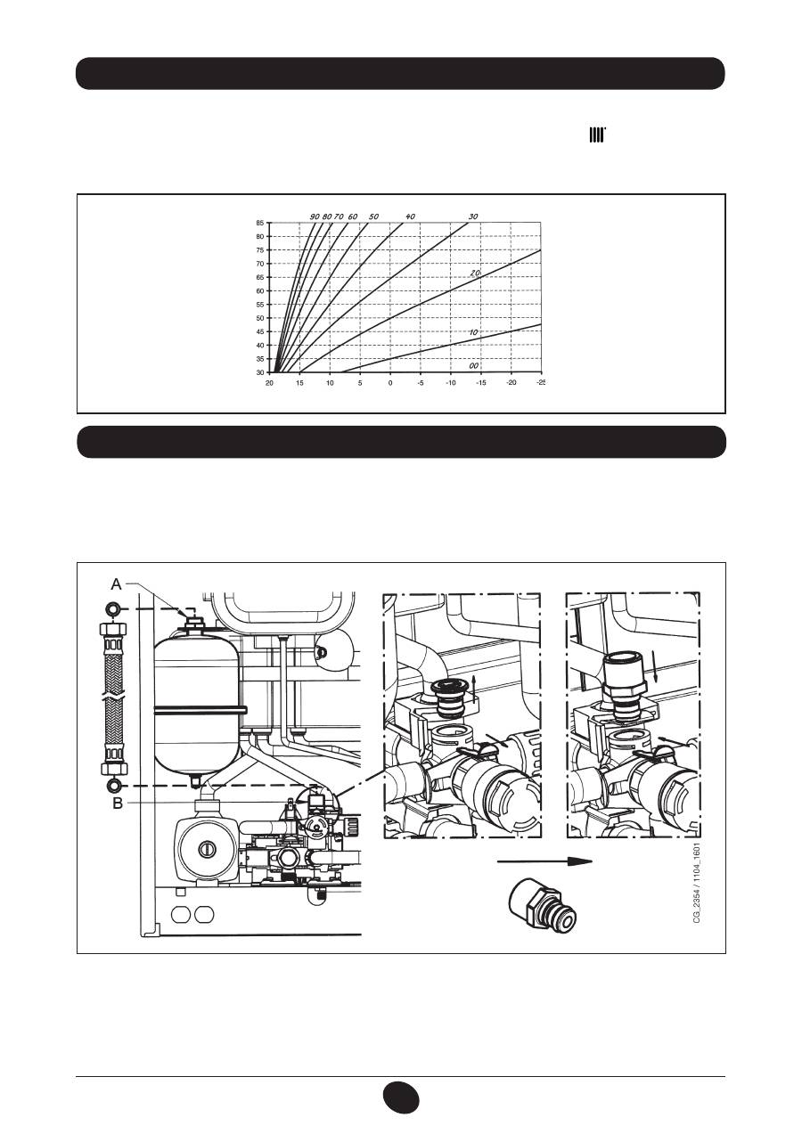
With the external sensor connected, the “
kt
” curve (Graph 2) can be changed by pressing
+/-
.
N.B.: In case of installation in an average living unit (good perimeter insulation and radiator systems), set the “
kt
” climate
curve to “25”.
TM
= Flow temperature range
Te
= External temperature
Graph 2
TM
Te
“kt” curves
1012_0501
DHW expansion vessel kit comprising:
- 1 stainless steel expansion vessel;
- 1 support for expansion vessel;
- 1 nipple G1/2”;
- 1 lock nut;
- 1 connection hose.
27. DHW EXPANSION VESSEL (AVAILABLE ON REQUEST)
Connect the hose (supplied as an accessory in the expansion vessel kit) to the two connectors A and B as shown in figure.
The DHW expansion vessel should be mounted if:
- the pressure of the water supply or lifting system is such as to require the installation of a pressure reducer (pressure
higher than 4 bar)
- a non-return valve is fitted to the water supply line
- the water supply network is insufficient for the expansion of the water contained in the storage boiler and it is necessary
to use the DHW expansion vessel.
80
71.06199.02 - EN
INSTALLATION INSTRUCTIONS
To optimise boiler efficiency, carry out the following annual controls:
• check the appearance and air-tightness of the gaskets of the gas and combustion circuits;
• check the state and correct position of the ignition and flame-sensing electrodes;
• check the state of the burner and make sure it is firmly fixed;
• check for any impurities inside the combustion chamber.
Use a vacuum cleaner to do this;
• check the gas valve is correctly calibrated;
• check the pressure of the heating system;
• check the pressure of the expansion vessel;
• check the fan works correctly;
• make sure the flue and air ducts are unobstructed.
• check the state of the boiler anode.
WARNINGS
Before commencing any maintenance operations, make sure the boiler is disconnected from the power supply.
Afterwards, move the knobs and/or operating parameters of the boiler to their original positions.
28. ANNUAL SERVICE
TIPS
For the efficient operation of the expansion vessel, the pressure of the water supply must be lower than 4 bar. If it is not,
install a pressure reducer. Adjust the pressure reducer to obtain a water supply pressure less than 4 bar.
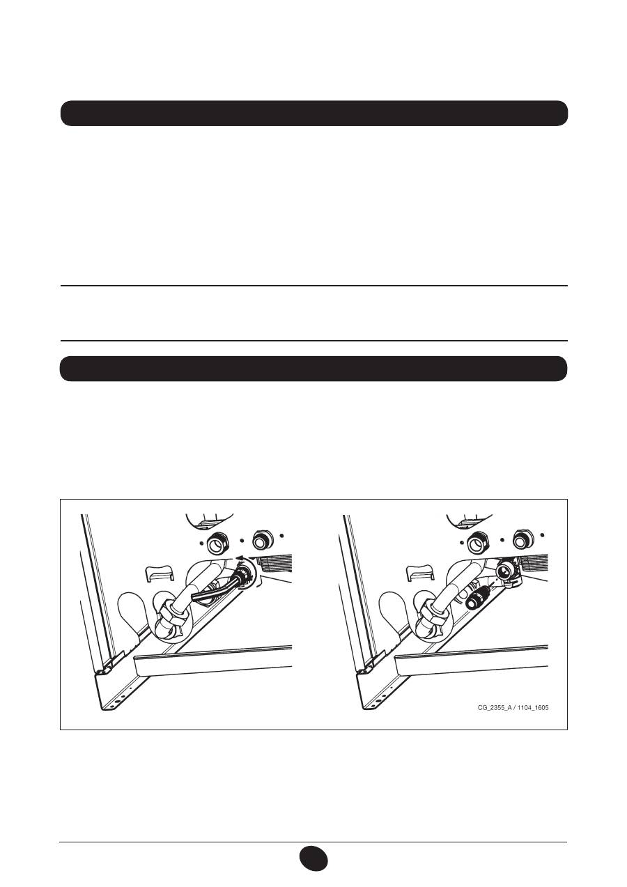
DRAINING THE BOILER CIRCUIT
Drain the boiler by opening the tap in the hydraulic assembly.
To drain the boiler using the drain tap located at the bottom, proceed as follows (fig. 14):
- close the boiler on/off valves;
- open the drain tap using an 8 mm hex wrench;
- drain the boiler;
- close the drain tap using the 8 mm hex wrench.
29. DRAINING THE BOILER CIRCUIT AND THE STORAGE BOILER
Figure 14

81
71.06199.02 - EN
INSTALLATION INSTRUCTIONS
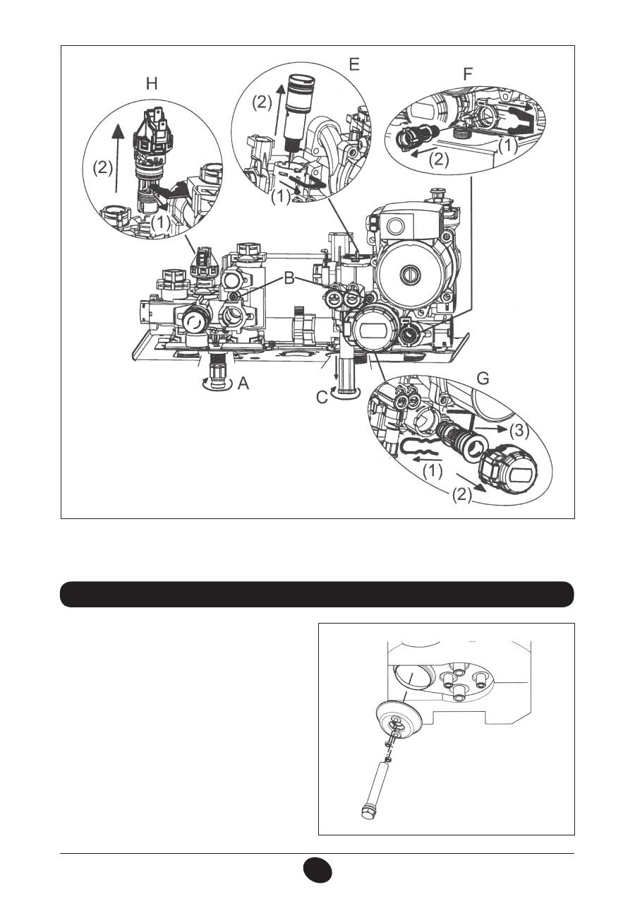
The DHW and CH filters are housed in special extractable cartridges. The CH cartridge is located on the CH return line
(figure 15F). To clean the filters, proceed as described below:
• switch off the boiler;
• shut the DHW inlet tap
• drain the water in the CH circuit by opening tap A in figure 15.
• remove the clip (1-F) from the filter as illustrated in the figure and take out the cartridge (2-F) containing the filter, taking
care not to apply excessive force;
• to extract the heating filter cartridge, first remove the 3-way valve motor (1-2G - figure 15);
• eliminate any impurities and deposits from the filter;
• reposition the filter in the cartridge and put it back into its housing, securing it with the clip.
WARNING
when replacing and/or cleaning the O-rings on the hydraulic assembly, only use Molykote 111 as a lubricant, not oil or grease.
30. CLEANING THE FILTERS
To clean, proceed as follows:
• Turn off the DHW inlet tap
• Drain the DHW system by opening a hot water tap
• Turn off the DHW outlet tap
• Remove the clip 1E in figure 15.
• Remove the filter (2E figure 15).
Dismount the water-water heat exchanger, as described in the next section, and clean it separately.
To clean the exchanger and/or DHW circuit, use Cillit FFW-AL or Benckiser HF-AL.
31. REMOVING SCALE FROM THE DHW CIRCUIT
The stainless steel plate-type water-water heat exchanger can be easily disassembled with an M4 spanner by operating
as described below:
• drain the system, just the boiler if possible,
through the drain tap
;
• drain the DHW system;
• remove the two screws at the front securing the water-water heat exchanger and pull it out (figure 15B).
32. DISMOUNTING THE WATER-WATER HEAT EXCHANGER
DRAINING THE STORAGE BOILER
Drain the water in the storage boiler as follows:
- close the water inlet tap;
- open a user tap;
- open the relative drain tap (Fig. 2-B);
- loosen the nut on the DHW outlet pipe at the bottom of the storage boiler.
82
71.06199.02 - EN
INSTALLATION INSTRUCTIONS
33. DISASSEMBLING THE BOILER ANODE
Check the state of the protective magnesium anode on
an annual basis
(before proceeding, empty the boiler circuit using the
relevant drain tap).
To disassemble the anode unit remove the boiler sensor
fixing clip, take it out and with a 27mm spanner (A) and
loosen the anode support nut.
CG_2341 / 1103_2303
A
WARNING
Pay great attention when dismantling the individual parts of the hydraulic assembly.
Do not use sharp tools, do not apply excessive force when removing the fixing clip.
Figure 15
CG_2326 / 1103_0401
83
71.06199.02 - EN
INSTALLATION INSTRUCTIONS
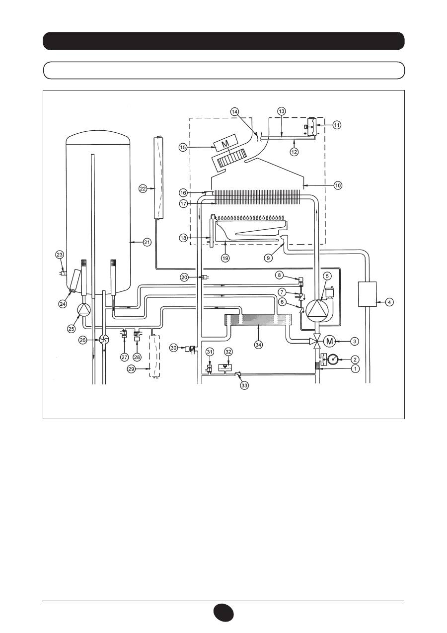
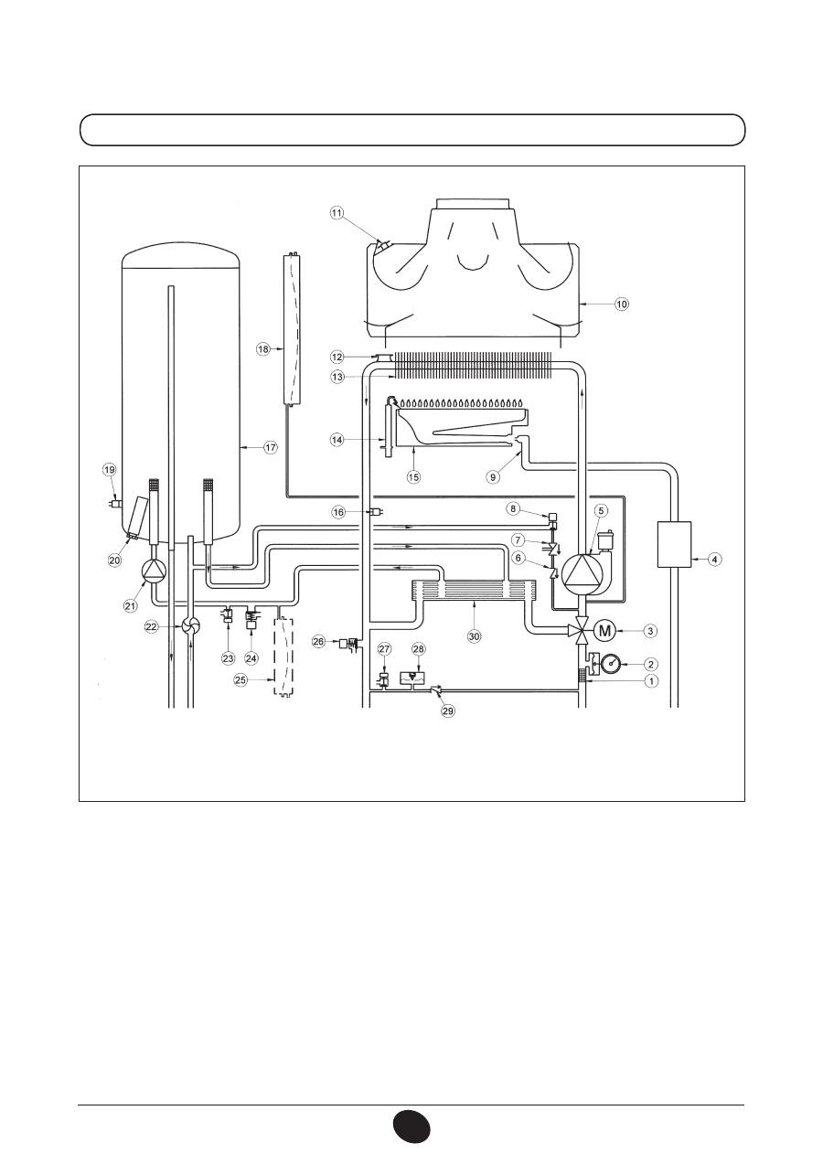
34. FUNCTIONAL CIRCUIT DIAGRAM
24 BIC FF
Figure 16
Heating flow
DHW
outlet
Gas
DHW
inlet
Heating return
Key:
1
heating filter
2
pressure gauge
3
powered 3-way valve
4
gas valve with gas diaphragm
5
heating circuit pump with deaerator
6
check valve
7
disconnector
8
boiler filling tap
9
gas train with injectors
10
fumes conveyor
11
air pressure switch
12
negative pressure point
13
positive pressure point
14
venturi tube
15
fun
16
safety thermostat
17
water-fumes exchanger
18
Ignition/flame detection electrode
19
burner
20
NTC domestic hot water sensor
21
storage boiler
22
heating circuit expansion vessel
23
NTC heating probe
24
sacrificial anode
25
DHW circuit pump
26
DHW priority sensor
27
storage boiler drain tap
28
DHW circuit safety valve
29
DHW circuit expansion vessel (accessory)
30
boiler safety valve
31
boiler drain tap
32
hydraulic pressure switch
33
check valve on automatic by-pass
34
plate exchanger
CG_2337 / 1104_0402
84
71.06199.02 - EN
INSTALLATION INSTRUCTIONS
24 BIC
Figure 17
Heating flow
DHW
outlet
Gas
DHW
inlet
Heating return
Key:
1
heating filter
2
pressure gauge
3
powered 3-way valve
4
gas valve with gas diaphragm
5
heating circuit pump with deaerator
6
check valve
7
disconnector
8
boiler filling tap
9
gas train with injectors
10
fumes conveyor
11
fumes thermostat
12
safety thermostat
13
water-fumes exchanger
14
Ignition/flame detection electrode
15
burner
16
NTC domestic hot water sensor
17
storage boiler
18
heating circuit expansion vessel
19
NTC heating probe
20
sacrificial anode
21
DHW circuit pump
22
DHW priority sensor
23
storage boiler drain tap
24
DHW circuit safety valve
25
DHW circuit expansion vessel (accessory)
26
boiler safety valve
27
boiler drain tap
28
hydraulic pressure switch
29
check valve on automatic by-pass
30
plate exchanger
CG_2338 / 1104_0403
85
71.06199.02 - EN
INSTALLATION INSTRUCTIONS
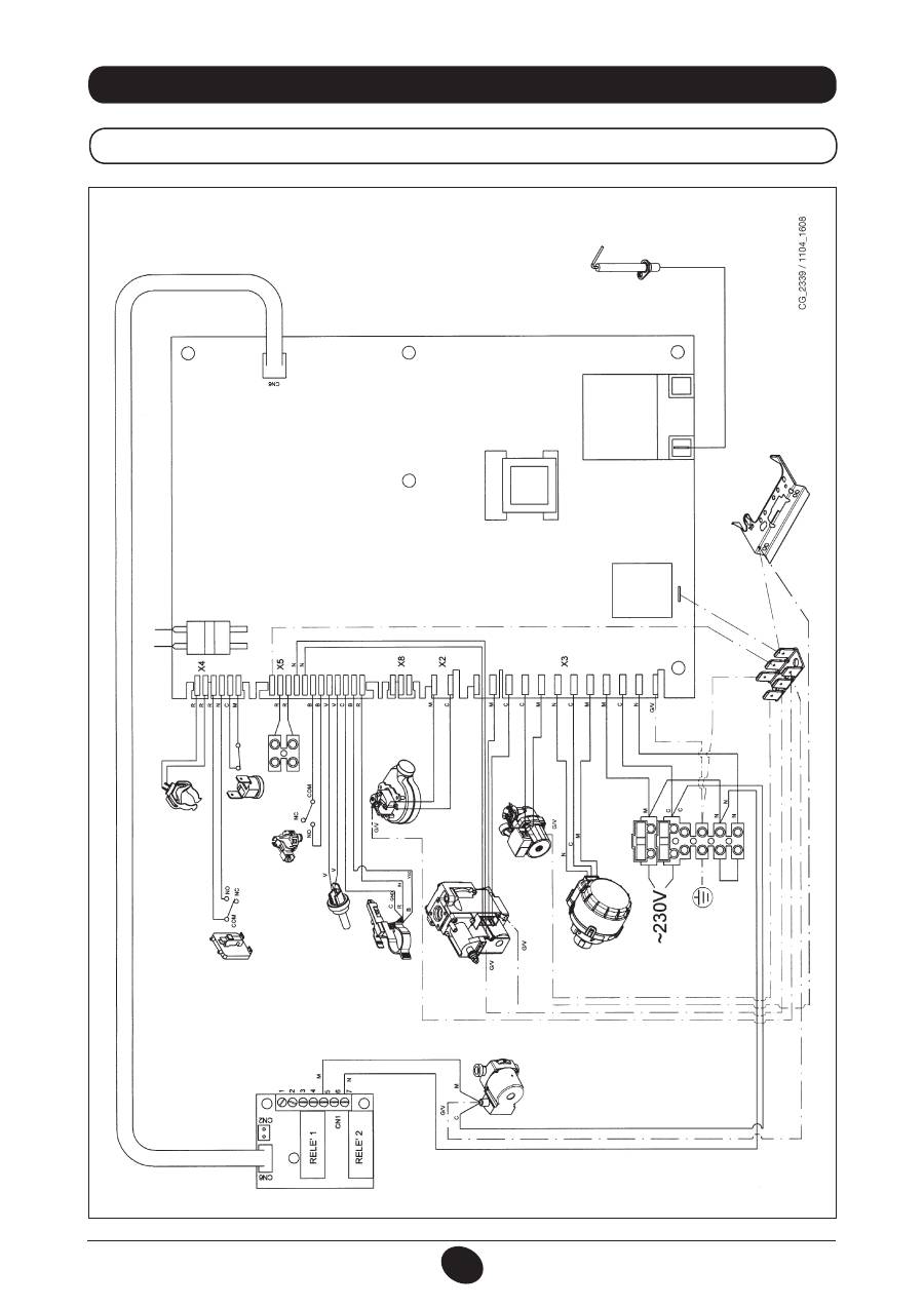
35. WIRING DIAGRAM
24 BIC FF
IGNITION/FLAME DETECTION
ELECTRODE
ROOM
THERMOST
AT
3-W
AY V
AL
VE
HEA
TING CIRCUIT
PUMP
FUN
DHW PRIORITY
SENSOR
NTC DOMESTIC
HOT W
ATER SENSOR
EXTERNAL
SENSOR
HYDRAULIC
PRESSURE SWITCH
SAFETY
THERMOST
AT
AIR PRESSURE
SWITCH
NTC HEA
TING
PROBE
PROGRAMMING
GAS V
AL
VE
DHW CIRCUIT
PUMP
Cable colours
C
= Light blue
M
= Br
own
N
= Black
R
= Red
G/V
= Y
ellow/Gr
een
B
= White
V
= Gr
een
86
71.06199.02 - EN
INSTALLATION INSTRUCTIONS
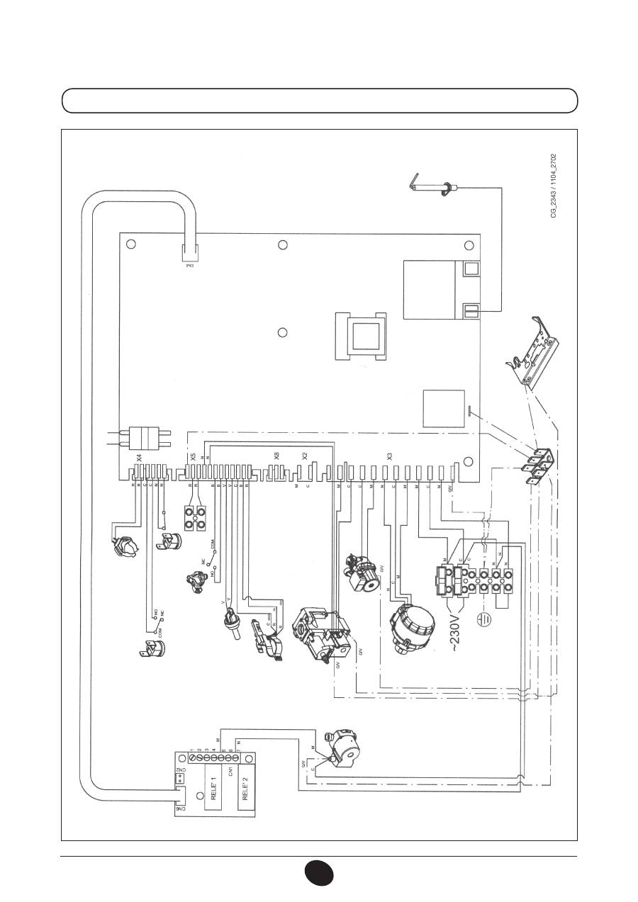
24 BIC
IGNITION/FLAME DETECTION
ELECTRODE
ROOM
THERMOST
AT
3-W
AY V
AL
VE
HEA
TING CIRCUIT
PUMP
DHW PRIORITY
SENSOR
NTC DOMESTIC HOT
W
ATER SENSOR
EXTERNAL
SENSOR
HYDRAULIC
PRESSURE SWITCH
SAFETY
THERMOST
AT
FUMES THERMOST
AT
NTC HEA
TING
PROBE
PROGRAMMING
GAS V
AL
VE
DHW CIRCUIT
PUMP
Cable colours
C
= Light blue
M
= Br
own
N
= Black
R
= Red
G/V
= Y
ellow/Gr
een
B
= White
V
= Gr
een

87
71.06199.02 - EN
INSTALLATION INSTRUCTIONS
36. TECHNICAL SPECIFICATIONS
As DE DIETRICH constantly strives to improve its products, it reserves the right to modify the information contained in this document at
any time and without prior notice. This document is issued purely for the sake of information and should not be considered as a contract
with third parties.
Model MS
24 BIC FF
24 BIC
Category
II
2H3P
II
2H3P
Rated heat input
kW
25,8
25,8
Reduced heat input
kW
11,9
11,9
Rated heat output
kW
24
23,3
kcal/h
20.600
20.000
Reduced heat output
kW
10,4
10,4
kcal/h
8.900
8.900
Useful efficiency according to directive 92/42/EEC
—
★★★
★★
Max. water pressure in CH system
bar
3
3
Expansion vessel capacity
l
7,5
7,5
Expansion vessel pressure
bar
1
1
Storage boiler capacity
l
42
42
DHW max. water pressure
bar
7
7
DHW min. dynamic water pressure
bar
0,15
0,15
Minimum DHW flow
l/min
2,0
2,0
DHW output at ∆T=25 °C
l/min
13,3
13,3
DHW output at ∆T=35 °C
l/min
9
9,5
Specific output (*)
l/min
17,7
17,7
Temperature range in heating system
°C
30/85
30/85
Temperature range in DHW system
°C
35/60
35/60
Type
—
C12-C32-C42-C52-C82-B22
B
11BS
Coaxial flue duct diameter
mm
60
-
Coaxial air duct diameter
mm
100
-
2-pipe flue duct diameter
mm
80
-
2-pipe air duct diameter
mm
80
-
Flue duct diameter
mm
-
125
Max. flue mass flow rate
kg/s
0,021
0,021
Min. flue mass flow rate
kg/s
0,021
0,019
Max. exhaust temperature
°C
135
110
Min. exhaust temperature
°C
108
85
NOx Class
—
3
3
Type of gas
—
G20
G20
—
G31
G31
Natural gas supply pressure
mbar
20
20
Propane gas supply pressure
mbar
37
37
Power supply voltage
V
230
230
Power supply frequency
Hz
50
50
Rated power supply
W
135
80
Net weight
kg
61
51
Dimensions
Height
mm
950
950
Width
mm
600
600
Depth
mm
466
466
Protection against humidity and water (**)
IP X5D
IP X5D
(*)
according to
EN 625 - (**)
according to
EN 60529
88
71.06199.02 - ES
INSTRUCCIONES PARA EL USUARIO
Estimado Cliente,
nuestra Empresa opina que su nueva caldera satisfará todas sus exigencias.
La compra de un producto
De Dietrich
garantiza lo que Ud. se espera: un buen funcionamiento y
un uso simple y racional.
Le pedimos que no ponga aparte estas instrucciones sin leerlas: contienen informaciones útiles para
una gestión correcta y eficaz de su caldera.
No se deben dejar las partes del embalaje (bolsas de plástico, poliestireno, etc.) al alcance de niños, en cuanto
que son potenciales fuentes de peligro.
1.
Advertencias antes de la instalación
89
2.
Advertencias antes de la puesta en marcha
89
3.
Puesta en marcha de la caldera
90
4.
Regulación de la temperatura ambiente y del agua sanitaria
91
5.
Descripción de la tecla (
) (Verano - Invierno - Sólo calefacción - Apagado)
91
6.
Llenado de la instalación
91
7.
Apagado de la caldera
92
8.
Cambio de gas
92
9.
Larga parada de la instalación. Protección contra el hielo (circuito de calefacción)
92
10.
Indicaciones y activación de los dispositivos de seguridad
93
11.
Instrucciones para el mantenimiento ordinario
93
12.
Advertencias generales
94
13.
Advertencias antes de la instalación
95
14.
Instalación de la caldera
95
15.
Dimensiones de la caldera
97
16.
Instalación de los conductos de descarga-aspiración
97
17.
Conexión eléctrica
101
18.
Conexión del termostato ambiente
101
19.
Modalidades de cambio de gas
102
20.
Visualización de los parámetros de la tarjeta electrónica en la pantalla de la caldera (función “info”)
104
21.
Configuración de los parámetros
105
22.
Dispositivos de regulación y seguridad
105
23.
Ubicación del electrodo de encendido y detección de llama
107
24.
Control de los parámetros de combustión
107
25.
Curvas de caudal / altura manométrica en la placa
107
26.
Conexión de la sonda exterior
108
27.
Depósito de expansión ACS (accesorio bajo pedido)
108
28.
Mantenimiento anual
109
29.
Vaciado del circuito caldera y del calentador
109
30.
Limpieza de los filtros
110
31.
Limpieza de la caliza del ACS
110
32.
Desmontaje del intercambiador agua-agua
110
33.
Desmontaje del ánodo del calentador
111
34.
Esquema funcional de los circuitos
112
35.
Esquema de conexión de los conectores
114
36.
Características técnicas
116
ÍNDICE
INSTRUCCIONES PARA EL USUARIO
INSTRUCCIONES PARA EL INSTALADOR
De Dietrich
declara que estas calderas llevan el marcado CE por cumplir los requi-
sitos esenciales de las siguientes Directivas:
- Directiva de gas 2009/142/CE
- Directiva de Rendimientos 92/42/CEE
- Directiva de Compatibilidad Electromagnética 2004/108/CE
- Directiva de baja tensión 2006/95/CE

89
71.06199.02 - ES
INSTRUCCIONES PARA EL USUARIO
Esta caldera sirve para calentar el agua a una temperatura inferior a la de ebullición, a presión atmosférica. Debe conec-
tarse a una instalación de calefacción y a una red de distribución de agua caliente sanitaria dentro de los límites de sus
prestaciones y de su potencia.
Antes de que la caldera sea conectada por un técnico calificado, según las normativas vigentes, es preciso realizar lo
siguiente:
a) Controlar que la caldera esté preparada para funcionar con el tipo de gas disponible. El tipo de gas se indica en el
embalaje y en la placa de datos del aparato.
b) Controlar que la chimenea tenga buen tiro, que no tenga estrangulamientos y no desemboquen en ella las salidas de
otros aparatos, salvo que haya sido realizada para este fin conforme a la reglamentación vigente.
c) Si la caldera se conecta a una chimenea preexistente, controlar que ésta se haya limpiado perfectamente, ya que el
desprendimiento de los depósitos de las paredes durante el funcionamiento puede obstruir la salida de humos.
d) Para mantener el funcionamiento correcto y la garantía del aparato, también es imprescindible respetar las siguientes
indicaciones:
1. Circuito sanitario:
1.1.
Si la dureza del agua es superior a 20 °F (1 °F = 10 mg de carbonato de calcio por litro de agua) es preciso instalar
un dosificador de polifosfatos o un sistema similar, conforme a las normas vigentes.
1.2.
Una vez montado el aparato, antes de utilizarlo es necesario hacer una limpieza a fondo de la instalación.
1.3.
Los materiales utilizados para el circuito de agua sanitaria del producto son conformes a la Directiva 98/83/CE.
2. Circuito de calefacción
2.1. instalación nueva
Antes de montar la caldera, hay que limpiar la instalación para eliminar los residuos de roscados, soldaduras y
disolventes, utilizando un producto comercial que no sea ni ácido ni alcalino, y que tampoco ataque los metales,
el plástico y la goma. Los productos aconsejados para la limpieza son:
SENTINEL X300 o X400 y FERNOX Regenerador para instalaciones de calefacción. Para el uso de estos productos,
seguir atentamente las instrucciones facilitadas por el fabricante.
2.2. instalación existente:
Antes de instalar la caldera, se debe vaciar totalmente la instalación y limpiarla de lodos y contaminantes con los
productos comerciales citados en el punto 2.1.
Para evitar que se formen incrustaciones en la instalación, utilizar inhibidores como SENTINEL X100 y FERNOX
Protectivo para instalaciones de calefacción. Para el uso de estos productos, seguir atentamente las instrucciones
facilitadas por el fabricante.
Se recuerda que los depósitos en la instalación de calefacción perjudican el funcionamiento de la caldera (por ej.
sobrecalentamiento y ruido del intercambiador).
La inobservancia de estas indicaciones invalida la garantía del aparato
.
1. ADVERTENCIAS ANTES DE LA INSTALACIÓN
El primer encendido debe ser efectuado por el Servicio de Asistencia Técnica autorizado, que tendrá que controlar:
a) Que los datos de placa sean conformes a los de las redes de alimentación (eléctrica, hidráulica y gas).
b) Que la instalación cumpla las normas vigentes.
c) Que la conexión eléctrica y la descarga a tierra se hayan realizado correctamente. La falta de conformidad con lo arriba
mencionado comporta la caducidad de la garantía.
Antes de la puesta en marcha, quitar la película de protección de la caldera. Para ello, no utilice herramientas o materiales
abrasivos, ya que podrían arruinar la pintura.
Este aparato no debe ser utilizado por personas (incluyendo los niños) con capacidades físicas, sensoriales o
mentales limitadas o que no tengan una experiencia ni conocimientos apropiados, a menos que actúen bajo la
vigilancia de una persona responsable de su seguridad o hayan recibido instrucciones sobre el uso del aparato.
2. ADVERTENCIAS ANTES DE LA PUESTA EN MARCHA
90
71.06199.02 - ES
INSTRUCCIONES PARA EL USUARIO
Para encender la caldera, actuar del siguiente modo:
1) conectar la caldera a la corriente eléctrica;
2) abrir la llave de paso del gas;
3) actuar sobre la tecla (
)
y situar la caldera en Verano ( ), Invierno (
) o sólo calefacción (
);
4) actuar sobre las teclas (
+/-
) para regular la temperatura del circuito de calefacción (
) y del agua caliente sanitaria
( ) para encender el quemador principal.
Cuando la caldera esté encendida, en la pantalla aparecerá el símbolo ( ).
En posición Verano ( ) el quemador estará encendido solo en caso de toma de agua caliente sanitaria.
ADVERTENCIA
Durante la primera puesta en marcha, es posible que el quemador no se encienda y la caldera se bloquee hasta que salga
todo el aire de la tubería del gas. En este caso se aconseja repetir las operaciones de encendido hasta que llegue gas al
quemador, pulsando la tecla ( ), durante 2 segundos como mínimo.
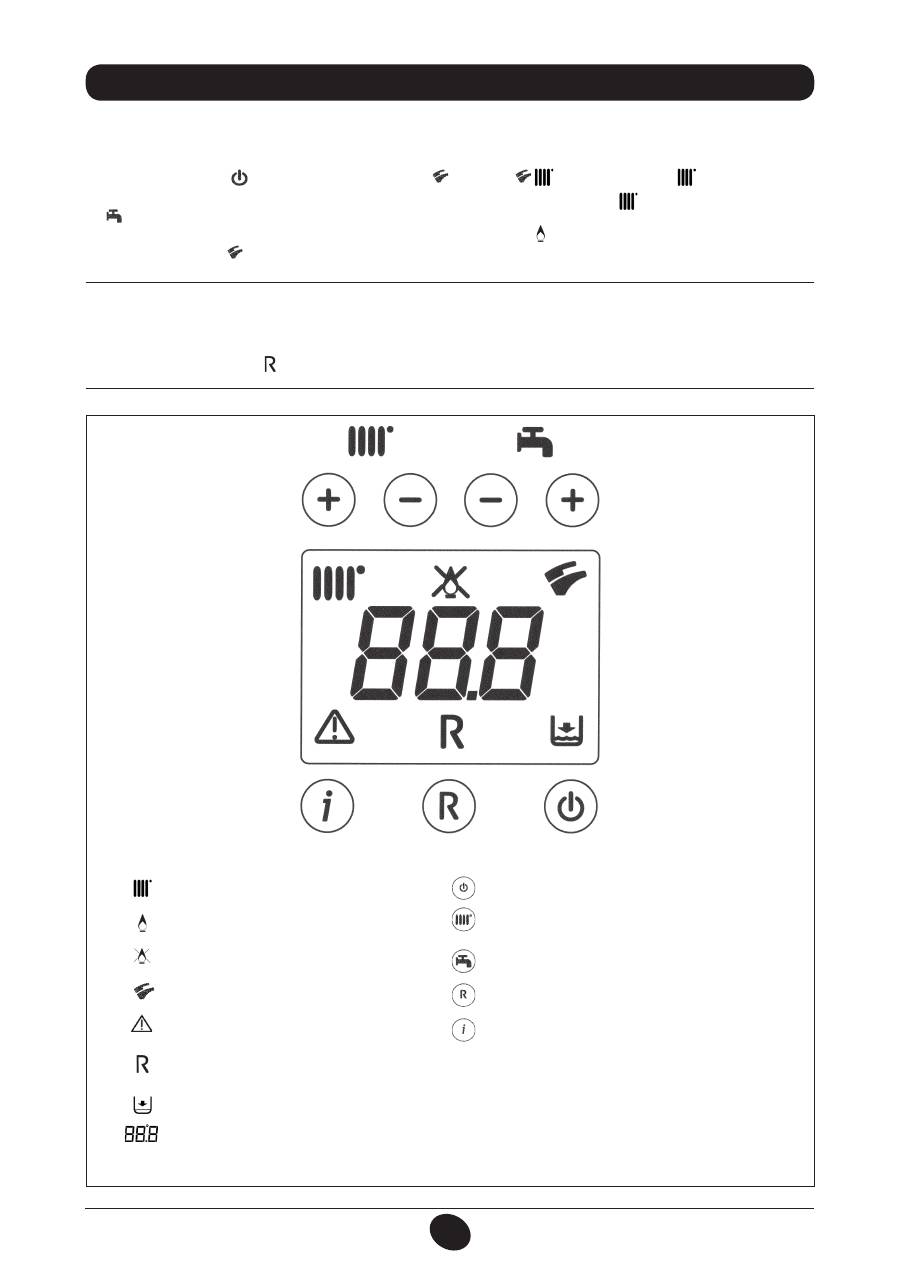
3. PUESTA EN MARCHA DE LA CALDERA
Funcionamiento en calefacción
Presencia de llama (quemador encendido)
Pérdida de llama (no se enciende)
Funcionamiento en sanitario
Anomalía genérica
Falta de agua (Presión instalación baja)
Indicación numérica (Temperatura, cód. anomalía, etc.)
RESET
LEYENDA DE LAS TECLAS
Figura 1
LEYENDA DE LOS SÍMBOLOS
Encendido / Apagado / Verano / Invierno / sólo calefacción
(
+/-
) : Regulación de la temperatura de calefacción
(
+/-
) : Regulación de la temperatura del agua sanitaria
Reset
Información
0805_2302 / C
G_2072
Оглавление
- SOMMAIRE
- 5. DESCRIPTION DES TOUCHES (ÉTÉ – HIVER – CHAUFFAGE SEULEMENT – ARRÊT)
- •
- 27. VASE EXPANSION SANITAIRE (ACCESSOIRE SUR DEMANDE)
- 5. DESCRIZIONE TASTO (Estate - Inverno - Solo riscaldamento - Spento)
- •
- 27. VASO DI ESPANSIONE SANITARIO (ACCESSORIO A RICHIESTA)
- 5. DESCRIPTION OF BUTTON (Summer - Winter - Heating only - Off)
- •
- 27. DHW EXPANSION VESSEL (AVAILABLE ON REQUEST)
- 5. DESCRIPCIÓN DE LA TECLA (Verano - Invierno - Sólo calefacción - Apagado)
- •
- 27. DEPÓSITO DE EXPANSIÓN ACS (ACCESSORIO BAJO PEDIDO)
- 5. ОПИСАНИЕ НА БУТОН (Лято – Зима – Само отопление – Изключен)
- 8. СМЯНА НА ВИДА ГАЗ
- 13. УКАЗАНИЯ ПРЕДИ МОНТАЖА
- 15. РАЗМЕРИ НА КОТЕЛА
- •
- 27. РАЗШИРИТЕЛЕН СЪД ЗА БИТОВИЯ КРЪГ (АКСЕСОАР ПО ЖЕЛАНИЕ)
- SPIS TREŚCI
- 1. OSTRZEŻENIA PRZED ZAINSTALOWANIEM
- 3. ROZRUCH KOTŁA
- 4. REGULACJA TEMPERATURY POKOJOWEJ I CIEPŁEJ WODY UŻYTKOWEJ
- 7. WYŁĄCZENIE KOTŁA 8. ZMIANA GAZU
- 11. INSTRUKCJE ODNOŚNIE KONSERWACJI ZWYKŁEJ
- 12. UWAGI OGÓLNE
- 13. WYMAGANIA INSTALACYJNE
- 15. WYMIARY KOTŁA
- 17. PODŁĄCZENIE ELEKTRYCZNE 18. PODŁĄCZENIE TERMOSTATU POKOJOWEGO
- 19. SPOSÓB ZMIANY RODZAJU GAZU
- •
- 21. USTAWIENIE PARAMETRÓW
- 24. KONTROLA PARAMETRÓW SPALANIA 25. CHARAKTERYSTYKA NATĘŻENIA PRZEPŁYWU/WYSOKOŚCI PODNOSZENIA
- 26. PODŁĄCZENIE CZUJNIKA ZEWNĘTRZNEGO
- 34. SCHEMAT FUNKCJONALNY OBWODÓW
- 35. SCHEMAT POŁACZEŃ ELEKTRYCZNYCH
- 36. CHARAKTERYSTYKA TECHNICZNA
- CUPRINS
- 1. AVERTISMENTE ANTERIOARE INSTALĂRII
- 3. PUNEREA ÎN FUNCŢIUNE A CENTRALEI TERMICE
- 4. REGLAREA TEMPERATURII AMBIANTE ŞI A TEMPERATURII APEI MENAJERE
- 7. OPRIREA CENTRALEI TERMICE 8. SCHIMBAREA TIPULUI DE GAZ
- 10. INTRAREA ÎN FUNCŢIUNE A DISPOZITIVELOR DE SIGURANŢA
- 12. AVERTISMENTE GENERALE
- 13. AVERTISMENTE ANTERIOARE INSTALĂRII 13. INSTALLAZIONE DELLA CALDAIA 14. INSTALAREA CENTRALEI TERMICE
- 14. DIMENSIONI CALDAIA 15. DIMENSIUNILE CENTRALEI TERMICE
- 17. CONECTAREA LA REŢEAUA ELECTRICĂ 18. CONECTAREA TERMOSTATULUI AMBIENTAL
- 19. MODALITĂŢI DE SCHIMBARE A TIPULUI DE GAZ
- 20. VIZUALIZAREA PARAMETRILOR PE AFIŞAJ (FUNCŢIE “INFO”)
- 21. SETAREA PARAMETRILOR
- 24. VERIFICAREA PARAMETRILOR DE COMBUSTIE 25. PERFORMANŢE DEBIT/ÎNĂLŢIME DE POMPARE
- 26. CONECTAREA SONDEI EXTERNE
- 34. DIAGRAMĂ FUNCŢIONALĂ CIRCUITE
- 35. DIAGRAMĂ CUPLARE CONECTORI
- 36. CARACTERISTICI TEHNICE
- ΠΕΡΙΕΧΟΜΕΝΑ
- 1. ΟΔΗΓΙΕΣ ΠΡΙΝ ΤΗΝ ΕΓΚΑΤΑΣΤΑΣΗ
- 3. ΘΕΣΗ ΣΕ ΛΕΙΤΟΥΡΓΙΑ ΤΟΥ ΛΕΒΗΤΑ
- 4. ΡΥΘΜΙΣΗ ΤΗΣ ΘΕΡΜΟΚΡΑΣΙΑΣ ΠΕΡΙΒΑΛΛΟΝΤΟΣ ΚΑΙ ΤΟΥ ΝΕΡΟΥ ΟΙΚΙΑΚΗΣ ΧΡΗΣΗΣ
- 7. ΣΒΗΣΙΜΟ ΤΟΥ ΛΕΒΗΤΑ 8. ΑΛΛΑΓΗ ΑΕΡΙΟΥ
- 10. ΕΝΔΕΙΞΕΙΣ-ΕΠΕΜΒΑΣΗ ΣΥΣΤΗΜΑΤΩΝ ΑΣΦΑΛΕΙΑΣ
- 12. ΓΕΝΙΚΕΣ ΠΛΗΡΟΦΟΡΙΕΣ
- 13. ΟΔΗΓΙΕΣ ΠΡΙΝ ΤΗΝ ΕΓΚΑΤΑΣΤΑΣΗ 13. INSTALLAZIONE DELLA CALDAIA 14. ΕΓΚΑΤΑΣΤΑΣΗ ΤΟΥ ΛΕΒΗΤΑ
- 14. DIMENSIONI CALDAIA 15. ΔΙΑΣΤΑΣΕΙΣ ΛΕΒΗΤΑ
- 17. ΗΛΕΚΤΡΙΚΗ ΣΥΝΔΕΣΗ 18. ΣΥΝΔΕΣΗ ΤΟΥ ΘΕΡΜΟΣΤΑΤΗ ΔΩΜΑΤΙΟΥ
- 19. ΤΡΟΠΟΣ ΑΛΛΑΓΗΣ ΑΕΡΙΟΥ
- 20. ΑΠΕΙΚΟΝΙΣΗ ΠΑΡΑΜΕΤΡΩΝ ΣΤΗΝ ΟΘΟΝΗ (ΛΕΙΤΟΥΡΓΙΑ «INFO»)
- 21. ΡΥΘΜΙΣΗ ΠΑΡΑΜΕΤΡΩΝ
- 24. ΕΛΕΓΧΟΣ ΠΑΡΑΜΕΤΡΩΝ ΚΑΥΣΗΣ 25. ΧΑΡΑΚΤΗΡΙΣΤΙΚΑ ΠΑΡΟΧΗΣ / ΜΑΝΟΜΕΤΡΙΚΟΥ ΥΨΟΥΣ ΣΤΗΝ ΠΛΑΚΑ
- 26. ΣΥΝΔΕΣΗ ΤΟΥ ΕΞΩΤΕΡΙΚΟΥ ΑΙΣΘΗΤΗΡΑ
- 34. ΛΕΙΤΟΥΡΓΙΚΟ ΣΧΕΔΙΟ ΚΥΚΛΩΜΑΤΩΝ
- 35. ΣΧΕΔΙΟ ΣΥΝΔΕΣΗΣ ΣΥΝΔΕΣΜΩΝ
- 36. ТЕХНИЧЕСКИ ХАРАКТЕРИСТИКИ
- 5. ОПИСАНИЕ КНОПКИ (Лето – Зима – Только Отопление – Выключено)
- •
- 27. РАСШИРИТЕЛЬНЫЙ БАК ГВС (ПРИНАДЛЕЖНОСТЬ ПО ЗАКАЗУ)
- 5. 锅炉运行模式选择
- 错误信息及故障表
- 27. 热水膨胀罐(可额外订购的配件)
