SCHNEIDER ELECTRIC XY2 CE: инструкция
Раздел: Электроустановочные изделия
Тип:
Инструкция к SCHNEIDER ELECTRIC XY2 CE
XY2 CE
User Instructions
Instruction de service
Instrucciones de usuario
Benutzeranleitung
Wartungsanleitung
05/2013
Head Office
35, rue Joseph Monier - CS 30323
F92500 Rueil-Malmaison Cedex
France
www.schneider-electric.com
Schneider Electric Industries SAS
1 mm min
0.04 in. min
1 mm min
0.04 in. min
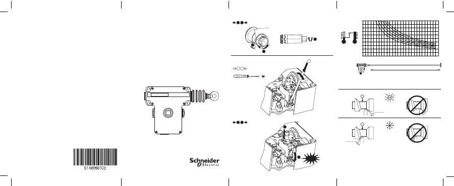
Fig. 4b
Fig. 4a
7
7
Fig. 9
3
3
4
4
1
1
2
2
ZALVBG
p
ZALVM
p
Ø 3,5 mm Maxi
Ø 0.14 in. Maxi
Click!
Fig. 3
°C
Fig. 8
1
1
2
2
2
ZB5 AZ905
2,2 Nm±0,2 /
19.5 lb-in±1.8
0
10
20
30
40
50
60
70
80
90
100
5
10
15
20
25
30
35
40
45
50
55
60
65
70
A B C
D E
F
L (m)
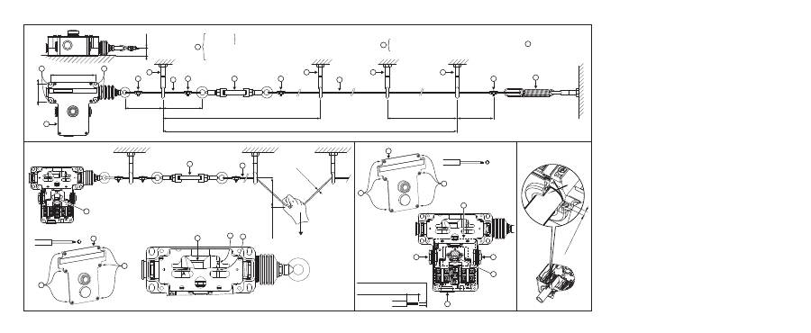
Fig. 1
0,15 ± 0,05 m
5.9 ± 1.96 in.
0,15 ± 0,05 m
5.9 ± 1.96 in.
2,5 m Mini – 5 m Maxi
98.42 in. Mini – 196.85 in. Maxi
70 m Maxi
2755.9 in. Maxi
2,5 m Mini – 5 m Maxi
98.42 in. Mini – 196.85 in. Maxi
120 mm
4.72 in.
41,5 - 48 mm
1.63 - 1.9 in.
20 mm
0.79 in.
0,15 ± 0,05 m
5.9 ± 1.96 in.
1
2
2
3
3
3
3
6
6
6
6
4
4
7
3
5
5
XY2CZ601
XY2CZ705
XY2CZ503
XY2CZ513
XY2CZ524
→
1,5 ± 0,1 N.m
1.1 ± 0.074 lb.ft
→
1,5 ± 0,5 N.m
1.1 ± 0.369 lb.ft
→
4,0 ± 0,5 N.m
2.95 ± 0.369 lb.ft
6
: XY2CZ702
Ød (mm)
f ≤ 400 mm
≤ 15.748 in.
Fig. 2
3
4
F1 ≤ 200 N
8
1
7
5
6
N°1 Phillips
®
2
2
1
8 ± 1 mm
0.315 ± 0.04 in.
1 x 0,5 mm
2
mini - 2 x 1,5 mm
2
Maxi
1 x AWG20 mini - 2 X AWG16 Maxi
N°1 Phillips
®
2
2
1
4
4
3
6
5
Fig. 6
XY2CE…H7
Fig. 7
Maxi 3,7 mm
maxi 0.15 in.
1
Table of Contents
English.........................................................................02-06 Français.......................................................................07-11 Español........................................................................12-16 Deutsch........................................................................17-21 Nederlands...................................................................22-26 Dansk...........................................................................27-31 Svenska.......................................................................32-36 Norsk............................................................................37-41 Suomi...........................................................................42-46 Italiano..........................................................................47-51 Português.....................................................................52-56 Ελληνικά .......................................................................57-61 中文 .............................................................................62-66 Русский ........................................................................67-71
schneider.fm Page 1 Friday, May 31, 2013 2:21 PM
2
English
EMERGENCY STOP TRIP WIRE SWITCHES
Mechanical endurance:
10,000 operating cycles
Safety information:
Read these instructions carefully and look at the equipment to become familiar with the device
before trying to install, operate, or maintain it. The following special messages may appear
throughout this documentation or on the equipment to warn of potential hazards or to call attention
to information that clarifies or simplifies a procedure.
Please note
Electrical equipment should be installed, operated, serviced, and maintained only by qualified
personnel. No responsibility is assumed by Schneider Electric for any consequences arising out of
the use of this material.
A qualified person is one who has skills and knowledge related to the construction and operation of
electrical equipment and the installation, and has received safety training to recognize and avoid the
hazards involved.
DANGER
indicates an imminently hazardous situation which, if not avoided,
will result in
death or serious
injury.
WARNING
indicates a potentially hazardous situation which, if not avoided,
can result in
death or serious
injury.
The addition of this symbol to a Danger or Warning safety label indicates that an electrical
hazard exists, which will result in personal injury if the instructions are not followed.
This is the safety alert symbol. It is used to alert you to potential personal injury hazards. Obey
all safety messages that follow this symbol to avoid possible injury or death.
DANGER WARNING
schneider.fm Page 2 Friday, May 31, 2013 2:21 PM
3
Installation (fig. 1)
1. Mount the device
solidly to a rigid support using cylindrical head screw M6, through holes
(tightening torque = 4±0.5 Nm /
2.95±0.369 lb.ft
)
2. Mount the cable guides
firmly to rigid elements
3. Attach the end spring
to a rigid element
4. Connect the cable
to the end spring
using a cable clamp
5. Pass the cable
through all the cable guides
6. Connect the cable
to the turnbuckle
using a cable clamp
7. Connect the turnbuckle
to the device
with a portion of cable
by passing it through a cable guide
and using cable clamps
NOTE: The list of accessories and springs can be found in the Schneider Electric catalog.
The diagrams show a "right-anchored" device: reverse the diagrams for a "left-anchored"
device. A support or element may be described as "rigid" if it is capable of supporting a load of 2,000 N in all
directions of solicitation.
RISK OF PHYSICAL INJURY
Inspect the cable in its entirety to identify the reason for the emergency stop order before restarting.
Failure to follow these instructions will result in death or serious injury.
RISK OF ELECTRICAL SHOCK, EXPLOSION OR ARC FLASH
• Switch off the power supply of the element acting as support
• Take care not to damage the parts of the support that are normally powered
• Visually inspect the good condition of the product
• Use appropriate personal protective equipment (PPE) and follow the relevant working instructions for
electrical environments. See NFPA 70E.
• Always use an appropriate electrical measuring device to confirm that the entire installation is powered
down.
Failure to follow these instructions will result in death or serious injury.
RISK OF UNINTENDED EQUIPMENT OPERATION
• Use Schneider Electric accessories only
• Ensure that the product is anchored along the same axis as the cable
• Mount the product to its support using 4 screws
• An end spring must be used
• Place the cable guides no less than 2
.
5 meters (8.2 feet) and no more than 5 meters (16.4 feet) apart
from each other
• Strip the cable at the cable clamp points
• Remove all objects placed on the cable or masking it
• Ensure that the cable is free to move
Failure to follow these instructions will result in death or serious injury.
RISK OF FALL, COLLISION OR CRUSHING
• Secure the cable traction zone
• Ensure that the cable is accessible along the entire traction zone
Failure to follow these instructions can result in death, serious injury, or equipment damage.
DANGER DANGER DANGER DANGER WARNING
schneider.fm Page 3 Friday, May 31, 2013 2:21 PM
Оглавление
- English
- DANGER DANGER DANGER DANGER WARNING
- DANGERDANGER DANGERWARNING
- DANGERDANGER DANGERDANGER
- DANGERDANGER WARNING DANGERDANGER DANGERDANGER
- Français
- DANGER DANGER DANGER DANGER DANGER AVERTISSEMENT
- DANGERDANGER DANGER DANGER AVERTISSEMENT
- DANGERDANGER DANGERDANGER
- DANGERDANGER AVERTISSEMENT DANGERDANGER DANGERDANGER
- Español
- PELIGRO PELIGRO PELIGRO ADVERTENCIA
- PELIGRO PELIGRO ADVERTENCIA
- PELIGRO PELIGRO
- PELIGRO ADVERTENCIA PELIGRO PELIGRO
- Deutsch
- GEFAHR GEFAHR GEFAHR WARNUNG
- GEFAHR GEFAHRWARNUNG
- GEFAHR GEFAHR
- GEFAHR WARNUNG GEFAHR GEFAHR
- Nederlands
- GEVAAR GEVAAR GEVAAR WAARSCHUWING
- GEVAAR GEVAAR WAARSCHUWING
- GEVAAR GEVAAR
- GEVAAR WAARSCHUWING GEVAAR GEVAAR
- Dansk
- FARE! FARE! FARE! ADVARSEL!
- FARE! FARE! ADVARSEL!
- FARE! FARE!
- FARE! ADVARSEL! FARE! FARE!
- Svenska
- FARA FARA FARA VARNING
- FARA FARAVARNING
- FARA FARA
- FARA VARNING FARA FARA
- Norsk
- FARE FARE FARE ADVARSEL
- FARE FAREADVARSEL
- FARE FARE
- FARE ADVARSEL FARE FARE
- Suomi
- VAARA VAARA VAARA VAROITUS
- VAARA VAARA VAROITUS
- VAARA VAARA
- VAARA VAROITUS VAARA VAARA
- Italiano
- PERICOLOPERICOLO PERICOLO ATTENZIONE
- PERICOLO PERICOLO ATTENZIONE
- PERICOLO PERICOLO
- PERICOLO ATTENZIONE PERICOLO PERICOLO
- Português
- PERIGO PERIGO PERIGO AVISO
- PERIGO PERIGO AVISO
- PERIGO PERIGO
- PERIGO AVISOPERIGO PERIGO
- Ελληνικά
- ΚΙΝΔΥΝΟΣ ΚΙΝΔΥΝΟΣ ΚΙΝΔΥΝΟΣ ΠΡΟΕΙΔΟΠΟΙΗΣΗ
- ΚΙΝΔΥΝΟΣ ΚΙΝΔΥΝΟΣ ΠΡΟΕΙΔΟΠΟΙΗΣΗ
- ΚΙΝΔΥΝΟΣ ΚΙΝΔΥΝΟΣ
- ΚΙΝΔΥΝΟΣ ΠΡΟΕΙΔΟΠΟΙΗΣΗ ΚΙΝΔΥΝΟΣ ΚΙΝΔΥΝΟΣ
- 中文
- ٲ呐 ٲ呐 ٲ呐娤⌈
- ٲ呐 ٲ呐娤⌈
- ٲ呐 ٲ呐
- ٲ呐 娤⌈ ٲ呐 ٲ呐
- Русский
- ОПАСНО!ОПАСНО! ОПАСНО! ВНИМАНИЕ!
- ОПАСНО! ОПАСНО! ВНИМАНИЕ!
- ОПАСНО! ОПАСНО!
- ОПАСНО! ВНИМАНИЕ! ОПАСНО! ОПАСНО!
