EXFO Photonic Solutions Div. FVA-600: 3 Getting Started with Your FVA-600 Variable Attenuator
3 Getting Started with Your FVA-600 Variable Attenuator: EXFO Photonic Solutions Div. FVA-600
3 Getting Started with Your
FVA-600 Variable
Attenuator
Turning the Unit On and Off
When you turn off the FVA-600, it saves the current attenuation, wavelength,
operation mode, and step size.
IMPORTANT
If you remove batteries (and the AC adapter is unplugged), the unit
will turn off without saving the above values.
If the battery level is low (and the AC adapter is unplugged), the unit
will save the above values and turn off.
To turn on the unit:
Press . The unit displays EXFO for a few seconds.
You may use it immediately under normal conditions unless the unit was not shut
down properly. In this case, the unit will mechanically recalibrate itself.
To turn off the unit:
Hold down a few seconds. The unit saves current settings automatically.
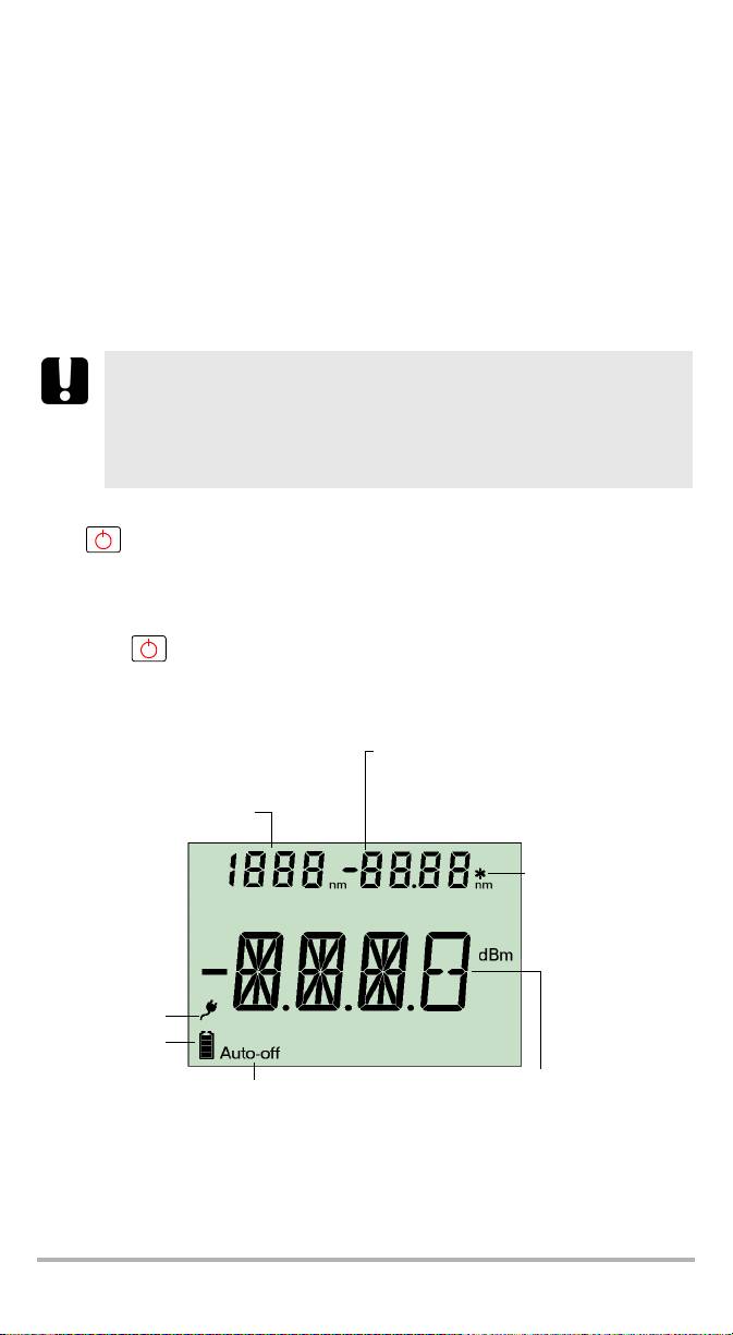
Display Description
Total attenuation in relative or power mode
Step size
Edition value for wavelength, power
Selected wavelength
Indicates a calibrated
wavelength in
wavelength edition
mode
AC adapter
plugged in
Batteries in use
(with level)
Total attenuation in absolute mode (dB)
Auto-off activated
Relative attenuation in relative mode (dB)
or power in power mode (dBm)
FVA-600 5
Getting Started with Your FVA-600 Variable Attenuator 6
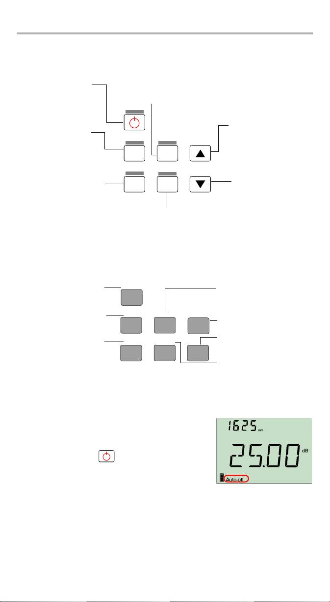
Keypad Description
The functions below are obtained by pressing on the corresponding buttons.
Increases value
(attenuation, power,
edition)
Abs/
Rel/
λ
Pwr
Step
Decreases value
Select
Size
(attenuation, power,
edition)
Confirms selection
Secondary Functions Keypad
The functions below are obtained by pressing and holding the button for a few
seconds.
Activating Automatic Shutdown (Auto-Off)
When auto-off is activated, the unit will turn off after
10 minutes of idle time.
To deactivate/reactivate auto-off:
When unit is on, press rapidly.
G
oes
to
next
prese
l
ecte
d
Turns on unit
wavelength
Auto-off mode
Confirms wavelength edition
Esc key
Switches between
measurement modes
Goes to next step size in list
Esc
Turns off unit
Edits selected
wavelength
Switches backlight
Backlight
Edit λ
Increases value rapidly
on or off
Decreases value rapidly
Searches for
Zero
Edit Pwr/Ref
reference positioning
Edits power for power
and reset to
operation mode and takes
attenuation in use
reference for relative
operation mode
Activating the Backlight
When operating the unit in the dark, use the backlight to make data on the display
more visible. The keypad buttons will also light for about 10 seconds.
Note: When the backlight is activated, you must always press a button once to
light the keypad, then press the actual button you want.
To activate/deactivate the backlight:
Abs/
Rel/
From the normal operating mode, hold down for a few seconds.
Pwr
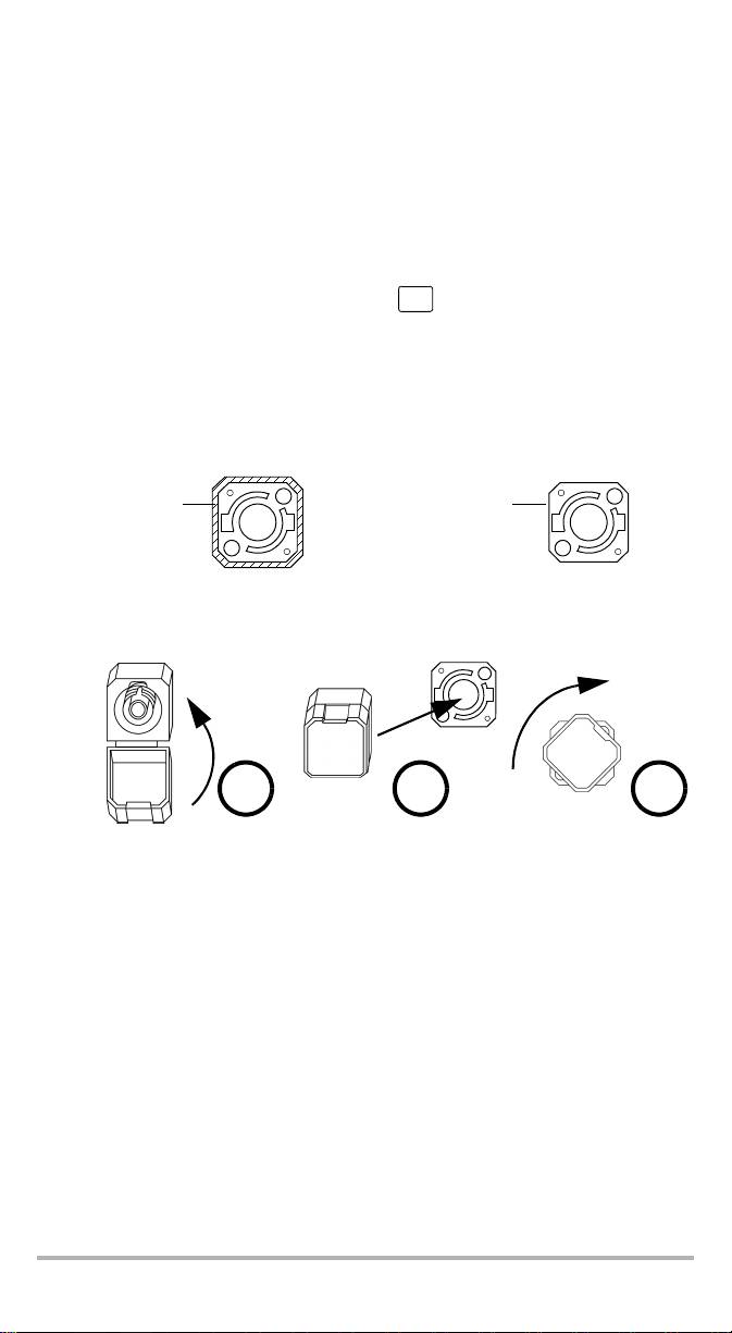
Installing the EXFO Universal Interface (EUI)
The EUIfixed baseplate is available for connectors with angled (APC) or non-angled
(UPC) polishing. A green border around the baseplate indicates that it is for
APC-type connectors.
Green border
Bare metal
indicates APC
(or blue border)
option
indicates UPC option
To install an EUI connector adapter onto the EUI baseplate:
1. Hold the EUI connector adapter so the dust cap opens downwards.
2 3 4
2. Close the dust cap in order to hold the connector adapter more firmly.
3. Insert the connector adapter into the baseplate.
4. While pushing firmly, turn the connector adapter clockwise on the baseplate to
lock it in place.
FVA-600 7

Getting Started with Your FVA-600 Variable Attenuator 8
Cleaning and Connecting Optical Fibers
IMPORTANT
To ensure maximum power and to avoid erroneous readings:
³ Always clean fiber ends as explained below before inserting
them into the port. EXFO is not responsible for damage or errors
caused by bad fiber cleaning or handling.
³ Ensure that your patchcord has appropriate connectors. Joining
mismatched connectors will damage the ferrules.
To connect the fiber-optic cable to the port:
1. Inspect the fiber using a fiber inspection microscope. If the fiber is clean,
proceed to connecting it to the port. If the fiber is dirty, clean it as explained
below.
2. Clean the fiber ends as follows:
2a. Gently wipe the fiber end with a lint-free swab dipped in isopropyl alcohol.
2b. Use compressed air to dry completely.
2c. Visually inspect the fiber end to ensure its cleanliness.
3. Carefully align the connector and port to prevent the fiber end from touching the
outside of the port or rubbing against other surfaces.
If your connector features a key, ensure that it is fully fitted into the port’s
corresponding notch.
4. Push the connector in so that the fiber-optic cable is firmly in place, thus
ensuring adequate contact.
If your connector features a screwsleeve, tighten the connector enough to firmly
maintain the fiber in place. Do not overtighten, as this will damage the fiber and
the port.
Note: If your fiber-optic cable is not properly aligned and/or connected, you
will notice heavy loss and reflection.
Оглавление
- 1 Introducing the FVA-600 Variable Attenuator
- 2 Safety Information
- 3 Getting Started with Your FVA-600 Variable Attenuator
- 4 Operating the FVA-600 Variable Attenuator
- 5 Maintenance
- 6 Troubleshooting
- 7 Warranty
- A Technical Specifications
- BTypical Test Configurations
- 1 Présentation de l’Atténuateur Variable FVA-600
- 2 Informations relatives à la sécurité
- 3 Initiation à votre Atténuateur Variable FVA-600
- 4 Utilisation de l’Atténuateur Variable FVA-600
- 5 Entretien
- 6 Dépannage
- 7 Garantie
- A Caractéristiques techniques
- B Configurations de test classiques
- 1FVA-600 可变衰减器简介
- 2 安全信息
- 3FVA-600 可变衰减器入门
- 4 操作 FVA-600 可变衰减器
- 5 维护
- 6 故障排除
- 7 保修
- A 技术规格
- B 典型测试配置
- 1 Presentación del Atenuador variable FVA-600
- 2 Información de seguridad
- 3 Primeros pasos con el Atenuador variable FVA-600
- 4 Funcionamiento del Atenuador variable FVA-600
- 5 Mantenimiento
- 6 Solución de problemas
- 7 Garantía
- A Especificaciones técnicas
- B Configuraciones de las comprobaciones típicas
- 1 Apresentação do Atenuador variável FVA-600
- 2Informações de segurança
- 3 Iniciar a utilização do seu Atenuador variável FVA-600
- 4 Funcionamento da Atenuador variável FVA-600
- 5 Manutenção
- 6 Resolução de avarias
- 7 Garantia
- A Especificações técnicas
- B Configurações de teste convencionais
- 1 Общие сведения о Регулируемый аттенюатор FVA-600
- 2 Информация о безопасности
- 3 Начало работы с Регулируемый аттенюатор FVA-600
- 4 Работа с устройством Регулируемый аттенюатор FVA-600
- 5 Обслуживание
- 6 Поиск и устранение неисправностей
- 7 Гарантия
- A Технические характеристики
- B Типовые конфигурации тестов
