MB QUART RAB 1450: AMPLIFIER FEATURE DESCRIPTION RAB 450 4-Channel Amplifier
AMPLIFIER FEATURE DESCRIPTION RAB 450 4-Channel Amplifier: MB QUART RAB 1450
5
AMPLIFIER FEATURE DESCRIPTION
RAB 450 4-Channel Amplifier
1 3 4
5
2
10
11
7 986
English
1
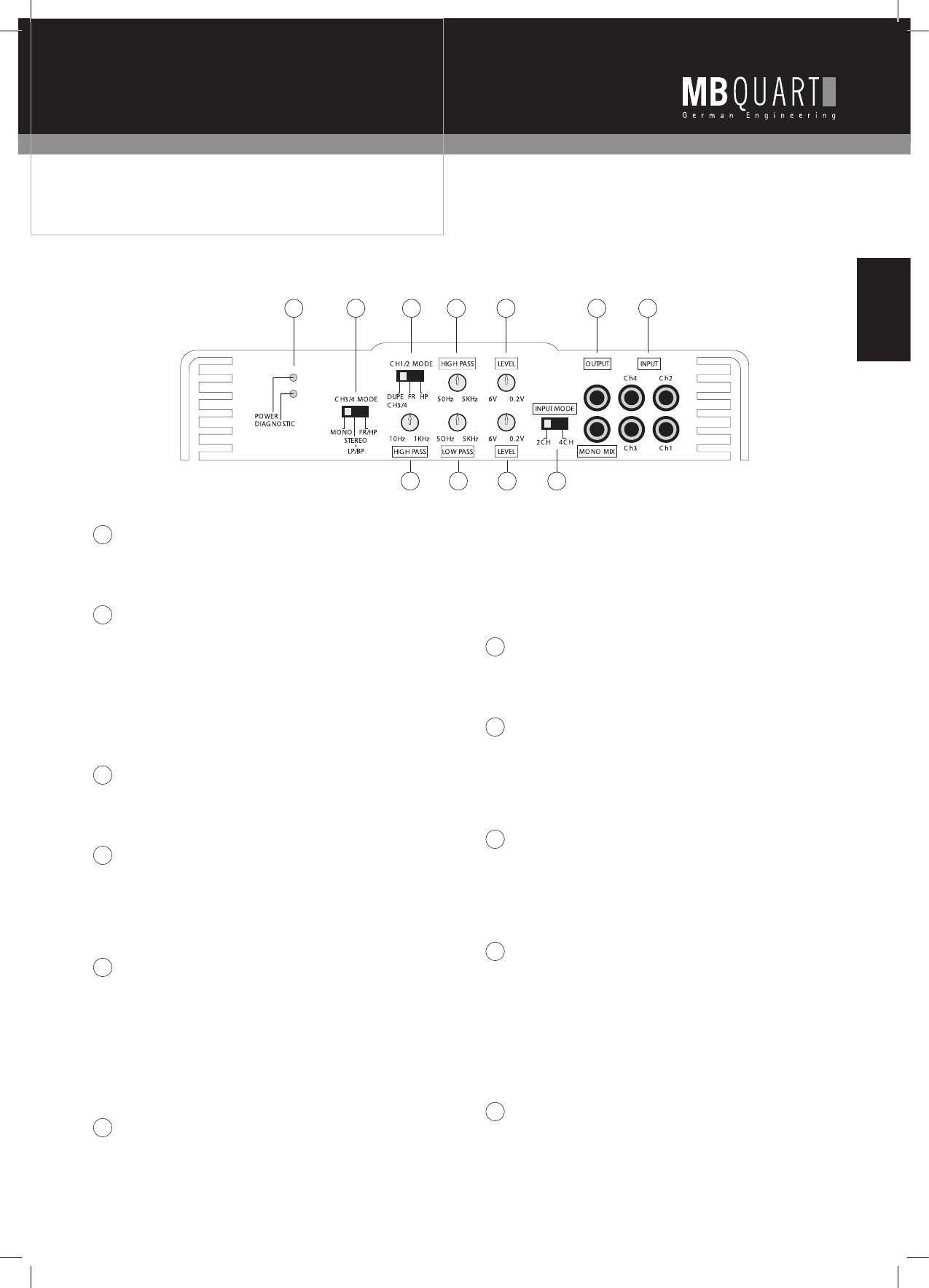
LED INDICATORS
3. Having this per manently connected to the 3 & 4 pair, allows
1. POWER: Lights up when power and remote turn-on is
us to use it at any time, either as a subsonic, when set from
applied.
20Hz to 40Hz or as the lower or high pass cut off frequency
2. DIAGNOSTICS: When lit, will indicate a fault condition.
control for active bandpass applications, in conjunction with
the LOW PASS filter when the CH3/4 MODE switch is in the
2
CH1/2 MODE
LOW PASS setting.
1. DUPE CH3/4 routes signal as selected by the amps 3 & 4
SELECT to the 1 & 2 amplifier pair. Note that in this case,
7
LOW PASS
channels 1 & 2 level will be set by the LEVEL CH3/4 control
1. Continuously variable low pass filter, 50 Hz to 5 kHz.
only, for an exact duplication of the 3 & 4 amplifier pair signal.
2. Signal routing and mode set by CH3/4 MODE and the LOW
2. FR (FULL RANGE) passes the full frequency range from CH1/2
PASS setting.
INPUT to the inter nal amplifiers.
3. HP (HIGH PASS) will send the range of frequencies above the
8
CH3/4 LEVEL
point set by the variable HIGH PASS control.
1. Sets CH3/4 input sensitivity to match the output level of the
radio/CD player.
3
CH1/2 HIGH PASS
2. Note that when the amps’ CH1/2 select switch is in the
1. Variable HIGH PASS filter from 50 Hz to 5 kHz.
DUPE CH3/4 position, the CH1/2 LEVEL control no longer af
2. This control is bypassed when CH1/2 is in DUPE 3/4 or
fects CH1/2.
FR (FULL RANGE) selection.
9
INPUT MODE
4
CH1/2 LEVEL
1. In the 2CH position, all four channels are provided signal
1. Sets CH1/2 input sensitivity to match the output level of the
from the CH1/2 RCA Inputs.
radio/CD player.
2. In the 4CH position, channels 1/2 receive input from CH1/2
2. Note that when the amps’ CH1/2 select switch is in the
RCA inputs, and channels 3/4 receive input from CH3/4 RCA
DUPE CH3/4 position, the CH1/2 LEVEL control no longer af
inputs.
fects CH1/2.
10
OUTPUT
5
CH3/4 MODE
1. This output can drive the input of other amplifiers in a
1. MONO is selected when bridging channels 3 & 4.
system (daisy chain).
2. LP/BP (LOW PASS/BANDPASS) will route those frequencies
2. In 4CH mode: Set switch 9 to 4CH. All 4 channels are mono
above the HIGH PASS setting and below the LOW PASS setting
mixed and then fed to both line out RCAs. This provides a
to the internal amplifier. In this mode the HIGH PASS acts as a
front/rear mono signal for constant non-faded sub bass to feed
SUBSONIC filter.
a sub amp.
3. FR/HP (FULL RANGE/HIGH PASS) bypasses the LOW PASS
3. In 2CH mode: Set switch 9 to 2CH. Only CH 1&2 are mono
setting and the frequencies reproduced are anything to above
mixed and fed to both line out RCAs.
the HIGH PASS setting.
11
INPUT
6
3&4 HIGH PASS
1. CH1-4 inputs to the amplifier, from the radio/CD line level
1. This high pass filter, variable from 10 Hz to 1 kHz, is per
(RCA) source with a range of 0.2 volts to 6 volts.
manently connected to the input of the amplifier pair.
2. Use a line converter if the radio/CD player has speaker (high
2. Since it can var y down to 10Hz, at that point it can be re
level) outputs only
garded as full range.
3. Depending on your system layout, follow the input descripti-
ons in section “Amplifier applications” of this manual.
Оглавление
- RAB 250 / RAB 450 / RAB 1450
- ENGLISH Index
- GENERAL INSTALLATION NOTES System design
- AMPLIFIER FEATURE DESCRIPTION RAB 250 2-Channel Amplifier
- AMPLIFIER FEATURE DESCRIPTION RAB 450 4-Channel Amplifier
- AMPLIFIER FEATURE DESCRIPTION
- AFTER INSTALLATION Setting up systems after installation for best performance
- AFTER INSTALLATION
- NOTES English
- DEUTSCH Inhaltsverzeichnis
- ALLGEMEINE INSTALLATIONSANWEISUNGEN Systemauslegung
- BESCHREIBUNG DER VERSTÄRKERKENNDATEN RAB 250 2-Kanal-Verstärker
- BESCHREIBUNG DER VERSTÄRKERKENNDATEN RAB 450 4-Kanal-Verstärker
- BESCHREIBUNG DER VERSTÄRKERKENNDATEN
- NACH DER INSTALLATION Einstellen der Anlage nach Installation zum Erzielen der besten Leistung
- NACH DER INSTALLATION Fehlersuche innerhalb der Anlage
- NOTIZEN Deutsch
- FRANÇAIS Sommaire
- CONSIGNES D‘INSTALLATION GÉNÉRALES Conception du système
- DESCRIPTION DES DONNÉES CARAC- TÉRISTIQUES DE L‘AMPLIFICATEUR Amplificateur 2 canaux RAB 250
- DESCRIPTION DES DONNÉES CARAC- TÉRISTIQUES DE L‘AMPLIFICATEUR Amplificateur 4 canaux RAB 450 Français
- DESCRIPTION DES DONNÉES CARACTÉRISTIQUES DE L‘AMPLIFICATEUR
- APRÈS L‘INSTALLATION Réglage de l‘installation pour obtenir les meilleures performances possibles
- APRÈS L‘INSTALLATION Recherche de pannes à l‘intérieur de l‘installation
- APRÈS L‘INSTALLATION
- ESPAÑOL Índice
- INSTRUCCIONES GENERALES PARA LA INSTALACIÓN
- DESCRIPCIÓN DE LOS DATOS CARAC- TERÍSTICOS DEL AMPLIFICADOR Amplificador de 2 canales RAB 250
- DESCRIPCIÓN DE LOS DATOS CARAC- TERÍSTICOS DEL AMPLIFICADOR Amplificador de 4 canales RAB 450 Español
- DESCRIPCIÓN DE LOS DATOS CARAC- TERÍSTICOS DEL AMPLIFICADOR
- DESPUÉS DE LA INSTALACIÓN Ajuste del equipo después de la instalación para obtener el mejor rendimiento
- DESPUÉS DE LA INSTALACIÓN Localización de errores en la instalación
- DESPUÉS DE LA INSTALACIÓN
- ITALIANO Indice
- ISTRUZIONI GENERALI PER L’INSTALLAZIONE System design
- DESCRIZIONE DELLE CARATTERISTICHE DELL’AMPLIFICATORE Amplificatore a due canali RAB 250
- DESCRIZIONE DELLE CARATTERISTICHE DELL’AMPLIFICATORE Amplificatore a quattro canali RAB 450 Italiano
- DESCRIZIONE DELLE CARATTERISTICHE DELL’AMPLIFICATORE Amplificatore Mono RAB 1450
- DOPO L’INSTALLAZIONE Impostazione del sistema dopo l’installazione per ottenerne il massimo rendimento.
- DOPO L’INSTALLAZIONE Diagnostica guasti nell’impianto
- DOPO L’INSTALLAZIONE
- PУССКИЙ Содержание
- ОБЩИЕ УКАЗАНИЯ ПО МОНТАЖУ Конструктивные параметры системы /
- ОПИСАНИЕ ПАРАМЕТРИЧЕСКИХ ДАННЫХ УСИЛИТЕЛЕЙ RAB 250 2-канальный усилитель
- ОПИСАНИЕ ПАРАМЕТРИЧЕСКИХ ДАННЫХ УСИЛИТЕЛЕЙ RAB 450 4-канальный усилитель Pусский
- ОПИСАНИЕ ПАРАМЕТРИЧЕСКИХ ДАННЫХ УСИЛИТЕЛЕЙ RAB 1450 Моно-усилитель
- ПОСЛЕ МОНТАЖА Настройка системы после монтажа для получения наилучшего эффекта звучания
- ПОСЛЕ МОНТАЖА Поиск неисправностей в пределах системы
- ПОСЛЕ МОНТАЖА
- AMPLIFIER APPLICATIONS RAB 250 2-Channel Amplifier
- AMPLIFIER APPLICATIONS RAB 250 2-Channel Amplifier
- AMPLIFIER APPLICATIONS RAB 450 4-Channel Amplifier
- AMPLIFIER APPLICATIONS RAB 450 4-Channel Amplifier
- AMPLIFIER APPLICATIONS RAB 1450 Mono Amplifier
- TECHNICAL DATA
- RAB 250 / RAB 450 / RAB 1450
