MB QUART REFERENCE SERIES 4-CHANNEL AMPLIFIER RAA4200: инструкция
Раздел: Бытовая, кухонная техника, электроника и оборудование
Тип: Компьютер
Инструкция к Компьютеру MB QUART REFERENCE SERIES 4-CHANNEL AMPLIFIER RAA4200

REFERENCE

INTRODUCTION
Dear Customer,
Congratulations on your purchase of the world’s finest brand of car audio equipment. At MB Quart, we are
pleased you chose our product. Through years of engineering expertise, hand craftsmanship and critical
testing procedures, we have created a wide range of products that reproduce music with all the clarity and
richness you deserve.
For maximum performance we recommend you have your new MB Quart product installed by an Authorized
MB Quart Dealer. Please read your warranty and retain your receipt and original carton for possible future use.
Great product and competent installations are only a piece of the puzzle when it comes to your system. Make
sure that your installer is using quality accessories in your installation. Poor quality RCA cables and speaker
wire can effect the performance and sound quality of your system. When installing, or having your system
installed, use the best. Insist on it! After all, your new system deserves nothing but the best.
To get a free brochure on MB Quart products and accessories,
in the U.S. call 1-800-962-7757 or FAX 1-800-327-3777.
For all other countries, call +49 6261 638-0 or FAX +49 6261 638-129.
PRACTICE SAFE SOUND™
Continuous exposure to sound pressure levels over 100dB may cause permanent hearing
loss. High powered auto sound systems may produce sound pressure levels well over
130dB. Use common sense and practice safe sound.
If, after reading your manual, you still have questions regarding this product, we recommend that you see
your MB Quart dealer. If you need further assistance, you can call us direct at 1-800-962-4412. Be sure to
have your serial number, model number and date of purchase available when you call.
The serial number can be found on the outside of the box. Please record it in the space provided below as
your permanent record. This will serve as verification of your factory warranty and may become useful in
recovering your amplifier if it is ever stolen.
Serial Number:___________________________________________
Model Number: __________________________________________
TABLE OF CONTENTS
Introduction. . . . . . . . . . . . . . . . . . . . . . . . . . . 2
Operation . . . . . . . . . . . . . . . . . . . . . . . . . 10-11
Safety Instructions . . . . . . . . . . . . . . . . . . . . . . 3
Set-up Features . . . . . . . . . . . . . . . . . . . . . . . . 10
Design Features . . . . . . . . . . . . . . . . . . . . . . 4-5
Front End Defeat . . . . . . . . . . . . . . . . . . . . . . . 10
Installation. . . . . . . . . . . . . . . . . . . . . . . . . . 5-9
Crossover . . . . . . . . . . . . . . . . . . . . . . . . . . . . . 10
Installation Considerations . . . . . . . . . . . . . . . . 5
Gain. . . . . . . . . . . . . . . . . . . . . . . . . . . . . . . . . . 11
Mounting Locations. . . . . . . . . . . . . . . . . . . . . . 6
Troubleshooting . . . . . . . . . . . . . . . . . . . . 11-12
Battery and Charging . . . . . . . . . . . . . . . . . . . . 6
Specifications. . . . . . . . . . . . . . . . . . . . . . . . . 12
Wiring the System. . . . . . . . . . . . . . . . . . . . . . . 7
Limited Warranty Information . . . . . . . . . . . . 13
NOTE: Review each section for more detailed information.
2
GETTING STARTED
Welcome to MB Quart! This manual is designed to provide information for the owner, salesperson and
installer. For those of you who want quick information on how to install this product, please turn to the
Installation Section of this manual. Other information can be located by using the Table of Contents. We, at
MB Quart, have worked very hard to make sure all the information in this manual is current. But, as we are
constantly finding new ways to improve our product, this information is subject to change without notice.
SAFET
Y
INSTRUCTIONS
This symbol with “WARNING” is intended to alert the user to the
presence of important instructions. Failure to heed the instructions will
result in severe injury or death.
This symbol with “CAUTION” is intended to alert the user to the
presence of important instructions. Failure to heed the instructions can
result in injury or unit damage.
CAUTION: To prevent injury and damage to the unit, please read and follow the instructions
in this manual. We want you to enjoy this system, not get a headache.
CAUTION If you feel unsure about installing this system yourself, have it installed by an
authorized MB Quart dealer.
CAUTION Before installation, disconnect the battery negative (-) terminal to prevent
damage to the unit, fire and/or possible injury.
CONTENTS OF CARTON
Model RAA4200 4-Channel Amplifier
(4) Speaker Plug Connectors
Installation & Operation Manual
(1) Power Plug Connector
Mounting Hardware Kit
(1) 8/32" Allen Wrench
The hardware kit included with each amplifier contains the mounting hardware necessary to secure the
amplifier to the vehicle.
Visit our web site for the latest information on all MB Quart products.
www.mbquart.com
3
DESIGN FEA
TURES
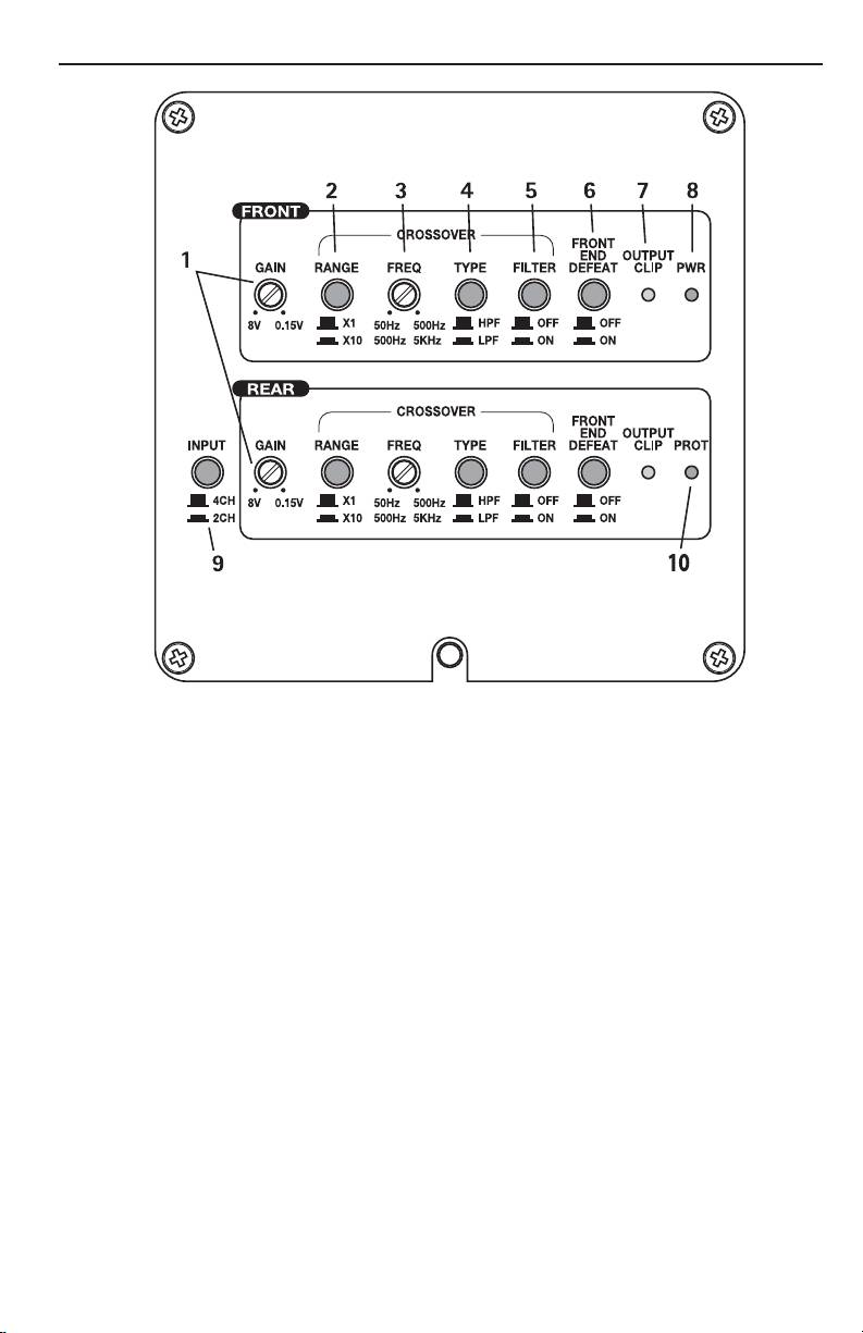
Controls
1. Gain Adjuster – These can be adjusted to match output levels from a variety of source units individually
for the front and rear inputs.
2. Crossover Multiplier Range Switch – Used to set the multiplier for the left and right crossover
frequencies between x1 and x10. A setting of x1 leaves the adjustable crossover frequency from
50-500Hz. A setting of x10 changes the adjustable crossover frequency to 500-5KHz (5000Hz)
3. Crossover Frequency Adjuster– Used to adjust the front and rear crossover frequency. Variable from 50Hz
to 500Hz in x1 mode, and 500-5KHz in x10 mode.
4. Crossover Type – Is used for selecting High-Pass Filter (HPF) or Low-Pass Filter (LPF) operation for the
front and rear speaker outputs.
5. Crossover Filter Switch – Off sets the crossover to all-pass, adjustments to the crossover range, freq, and
type are bypassed. On allows adjustments to the crossover settings to be used.
6. Front End Defeat – Used to reroute the input signal around the signal processing circuitry within the
amplifier. While in the ON position, all gain and crossover functions are bypassed.
7. Clipping LED Indicators – These Yellow LEDs illuminate if clipping is detected for either the front or rear
channel outputs.
8. Power LED – This Green LED illuminates when the unit is turned on.
9. 2/4 Channel Switch – Pressing this switch in, switches the inputs to a 2-channel mode, allowing
connection to only the front inputs with a 4-channel output.
10. Protect LED – This Red LED illuminates if a short circuit or too low of an impedance is detected at the
speaker connections or if the amplifier reaches thermal protection. The amplifier will automatically shut
down if this occurs.
4
DESIGN FEA
TURES
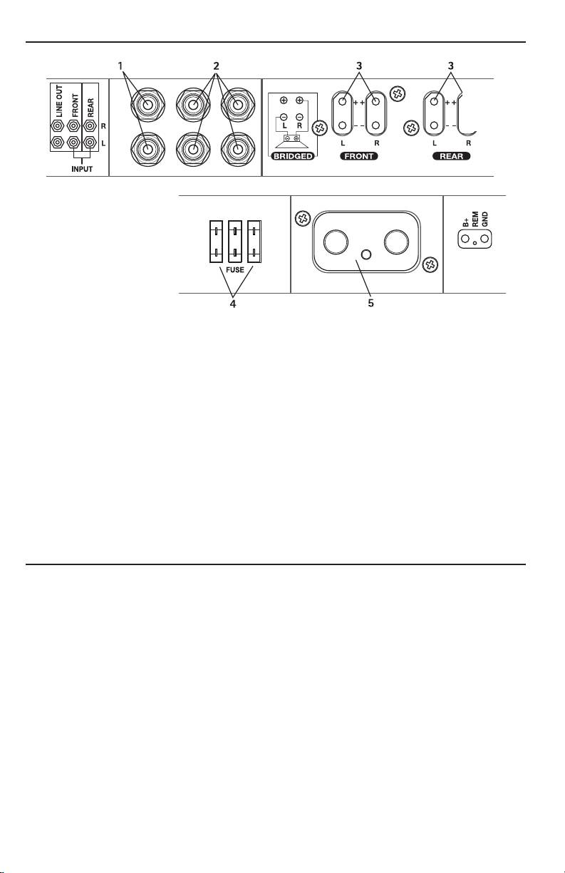
Connections
Left Side
Right Side
1. RCA Line Output Jacks – These outputs provide a convenient source for daisy-chaining an additional
amplifier without running an extra set of RCA cables from the front of the vehicle. These are pass-thru
only and are not effected by crossover or gain adjustments.
2. RCA Input Jacks – The industry standard RCA jacks provide an easy connection for line level input. They
are plated to resist the signal degradation caused by corrosion.
3. Speaker Plug Receptacle – Receptacle for the speaker plug connector. These connectors (+ and –) will
accept wire sizes from 12 AWG to 18 AWG.
4. Fuses – These ATC fuses are easily accessible in case of failure. Always replace fuses with same type and
rating. See Specifications for fuse ratings.
5. Power Plug Receptacle – Receptacle for the power plug connector. The power (+12V DC) and ground
wire connectors will accommodate up to a 2 AWG wire. The Remote wire connector will accommodate
sizes from 12 AWG to 18 AWG. The Remote terminal is used to remotely turn-on and turn-off the
amplifier when +12V DC is applied.
INSTALL
ATION
INSTALLATION CONSIDERATIONS
The following is a list of tools needed for installation:
Volt/Ohm Meter
Hand held drill w/assorted bits
Wire strippers
1/8" diameter heatshrink tubing
Wire crimpers
Assorted connectors
Wire cutters
Adequate Length—Red Power Wire
#2 Phillips screwdriver
Adequate Length—Remote Turn-on Wire
Battery post wrench
Adequate Length—Black Grounding Wire
This section focuses on some of the vehicle considerations for installing your new amplifier.
Pre-planning your system layout and best wiring routes will save installation time. When deciding on the
layout of your new system, be sure that each component will be easily accessible for making adjustments.
5

INST
ALLATION
CAUTION: If you feel unsure about installing this system yourself, have it installed by a
authorized MB Quart Dealer.
CAUTION: Before installation, disconnect the battery negative (-) terminal to prevent
damage to the unit, fire and/or possible injury.
Before beginning any installation, follow these simple rules:
1. Be sure to carefully read and understand the instructions before attempting to install the unit.
2. For safety, disconnect the negative lead from the battery prior to beginning the installation.
3. For easier assembly, we suggest you run all wires prior to mounting your unit in place.
4. Route all of the RCA cables close together and away from any high current wires.
5. Use high quality connectors for a reliable installation and to minimize signal or power loss.
6. Think before you drill! Be careful not to cut or drill into gas tanks, fuel lines, brake or hydraulic lines,
vacuum lines or electrical wiring when working on any vehicle.
7. Never run wires underneath the vehicle. Running the wires inside the vehicle provides the best protection.
8. Avoid running wires over or through sharp edges. Use rubber or plastic grommets to protect any wires
routed through metal, especially the firewall.
9. ALWAYS protect the battery and electrical system from damage with proper fusing. Install the appropriate
fuse holder and fuse on the +12V power wire within 18” (45.7 cm) of the battery terminal.
10. When grounding to the chassis of the vehicle, scrape all paint from the metal to ensure a good, clean
ground connection. Grounding connections should be as short as possible and always be connected to
metal that is welded to the main body, or chassis, of the vehicle.
MOUNTING LOCATIONS
Engine Compartment
Never mount this unit in the engine compartment. Mounting the unit in the engine compartment will void
your warranty.
Trunk Mounting
Mounting the amplifier vertically will provide adequate cooling of the amplifier.
Mounting the amplifier on the floor of the trunk will provide the best cooling of the amplifier.
Mounting the amplifier upside down to the rear deck of the trunk will not provide proper cooling and will
severely affect the performance of the amplifier and is strongly not recommended.
Passenger Compartment Mounting
Mounting the amplifier in the passenger compartment will work as long as you provide a sufficient amount of
air for the amplifier to cool itself. If you are going to mount the amplifier under the seat of the vehicle, you
must have at least 1" (2.54cm) of air gap around the amplifier's fan intake and top exhaust vents.
Mounting the amplifier with less than 1" (2.54cm) of air gap around the amplifier in the passenger
compartment will not provide proper cooling and will severely affect the performance of the amplifier and is
strongly not recommended.
BATTERY AND CHARGING
Amplifiers will put an increased load on the vehicle's battery and charging system. We recommend checking
your alternator and battery condition to ensure that the electrical system has enough capacity to handle the
increased load of your stereo system. Stock electrical systems which are in good condition should be able to
handle the extra load of any MB Quart amplifier without problems, although battery and alternator life can
be reduced slightly. To maximize the performance of your amplifier, we suggest the use of a heavy duty
battery and an energy storage capacitor.
6
INST
ALLATION
WIRING THE SYSTEM
CAUTION: If you do not feel comfortable with wiring your new unit, please see your local
authorized MB Quart Dealer for installation.
CAUTION: Before installation, disconnect the battery negative (-) terminal to prevent
damage to the unit, fire and/or possible injury.
CAUTION: Avoid running power wires near the low level input cables, antenna, power
leads, sensitive equipment or harnesses. The power wires carry substantial
current and could induce noise into the audio system.
1. Plan the wire routing. Keep RCA cables close together but isolated from the amplifier's power cables and
any high power auto accessories, especially electric motors. This is done to prevent coupling the noise
from radiated electrical fields into the audio signal. When feeding the wires through the firewall or any
metal barrier, protect them with plastic or rubber grommets to prevent short circuits. Leave the wires
long at this point to adjust for a precise fit at a later time.
2. Remove the four (4) 8/32 allen head screws holding the connection end cover in place (this is the end
without the vents for the fans). Keep the cover and screws in a safe place for reinstallation when
mounting and wiring is complete.
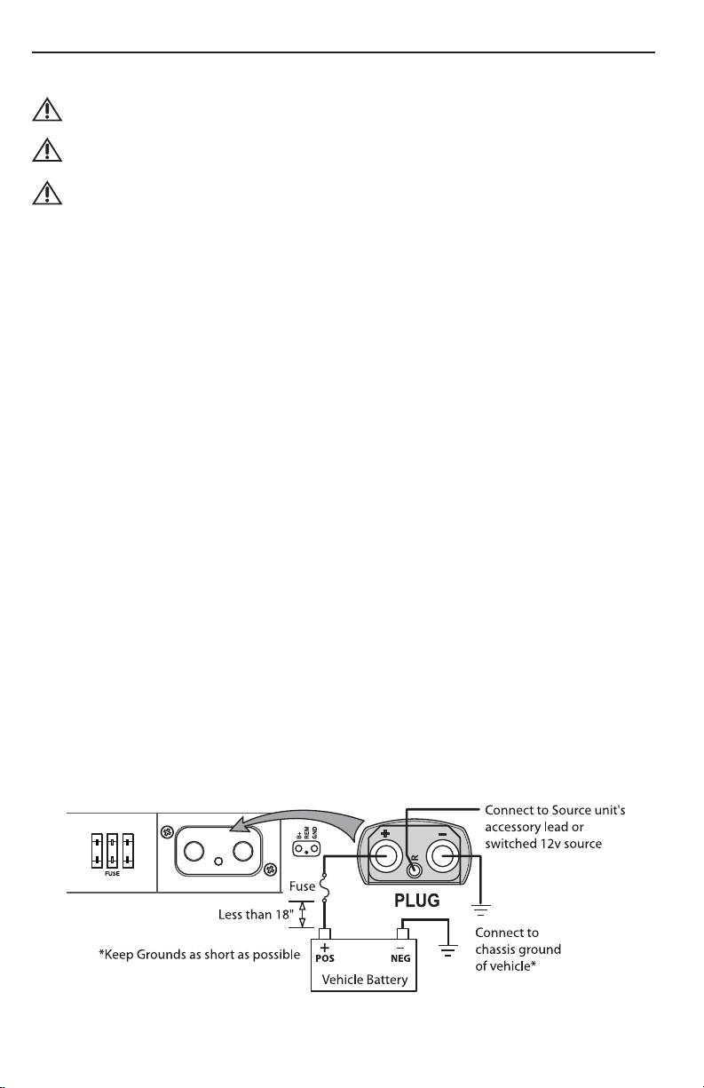
3. Prepare the RED wire (power cable) by stripping 1/2" of insulation from the end of the wire. Insert the
bared wire into the “+” terminal on the plug connector. Tighten the set screw with a 3/32" allen wrench
to secure the cable in place.
NOTE: The "+" (positive) cable MUST be fused 18" or less from the vehicle's battery. Install the fuseholder
under the hood and ensure connections are water tight.
4. Trim the RED wire (power cable) within 18" of the battery and splice in a inline fuse holder. See
Specifications for the rating of the fuse to be used. DO NOT install the fuse at this time.
5. Strip 1/2" from the battery end of the power cable and crimp a large ring terminal to the cable. Use the
ring terminal to connect to the battery positive terminal.
6. Prepare the BLACK wire (Ground cable) by stripping 1/2" of insulation from the end of the wire. Insert the
bared wire into the “-” terminal on the plug connector. Tighten the set screw with a 3/32" allen wrench
to secure the cable in place. Prepare the vehicle chassis ground by scraping any paint from the metal
surface and thoroughly clean the area of all dirt and grease. Strip the other end of the wire and attach a
ring connector. Fasten the cable to the chassis using a non-anodized screw and a star washer.
NOTE: Keep the length of the BLACK wire (Ground) as short as possible. Always less than 30"(76.2cm).
7. Prepare the Remote turn-on wire by stripping 1/2" of insulation from the end of the wire. Insert the
bared wire into the “R” terminal on the plug connector. Tighten the set screw with a 3/16" allen wrench
to secure the cable in place. Connect the other end of the Remote wire to a switched 12 volt positive
source. The switched voltage is usually taken from the source unit's accessory lead. If the source unit
does not have this output available, the recommended solution is to wire a mechanical switch in line
with a 12 volt source to activate the amplifier manually.
Power Connection
7
INST
ALLATION
8. Securely mount the amplifier to the vehicle or amp rack. Be careful not to mount the amplifier on
cardboard or plastic panels. Doing so may enable the screws to pull out from the panel due to road
vibration or sudden vehicle stops.
9. Connect source signal by plugging the RCA cables into the input jacks at the amplifier.
CAUTION: Always ensure power is off or disconnected at the amplifier before connecting
RCA cables. Failure to do so may cause injury, damage to the amplifier and/or
connected components.
10. Connect the speakers. Strip the speaker wires 1/2" and insert into the speaker plug connector and tighten
the set screw to secure into place. Be sure to maintain proper speaker polarity. DO NOT chassis ground
any of the speaker leads as unstable operation may result.
11. Perform a final check of the completed system wiring to ensure that all connections are accurate. Check
all power and ground connections for frayed wires and loose connections which could cause problems.
12. Ensure the amplifier is mounted securely and reinstall the end cover. Install an inline fuse near the
battery connection.
NOTE: Follow the diagrams for proper signal polarity.
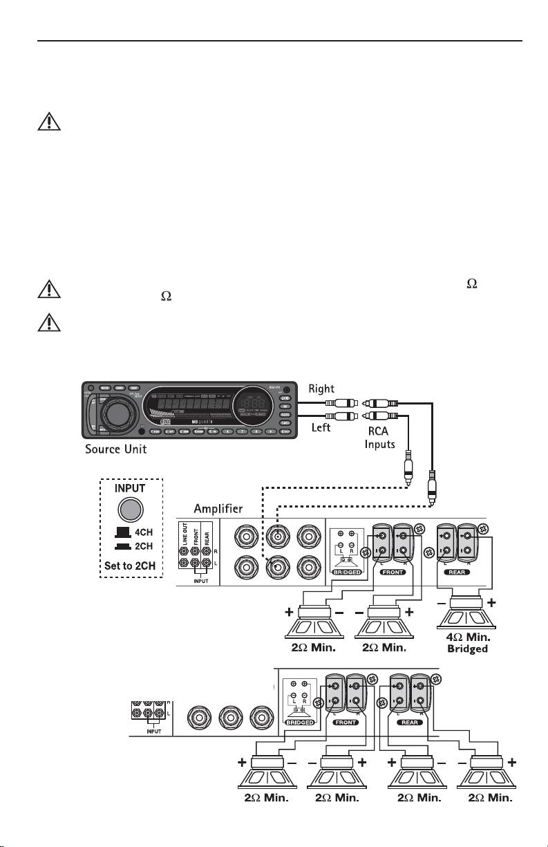
CAUTION: These amplifiers are not recommended for impedance loads below 2 stereo
and 4 bridged.
CAUTION: Do not attempt to connect the source units speaker leads directly to the RCA
connections of this amplifier, as damage to the source unit and/or the
amplifier may result.
2-Channel Wiring
• RCA Inputs connect to FRONT inputs only.
• 2/4 CH SWITCH push in to set to 2CH.
• Gain (Front & Rear) - is set independently to
suit application.
• Crossover (Front & Rear) - is set independently
to suit application.
8
INST
ALLATION
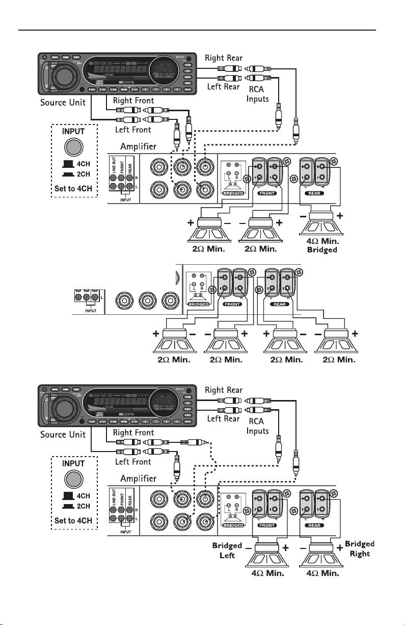
4-Channel Wiring
• 2/4 CH SWITCH push in to set to 4CH.
• Gain (Front & Rear) - is set independently
to suit application.
• Crossover (Front & Rear) - is set
independently to suit application.
Stereo Bridged
9
OPERA
TION
SET-UP FEATURES
The MB Quart R Series amplifier offers a wide range of selections for the user to create a listening
environment that meets your personal preference.
Before making final adjustments, read through the descriptions for each feature to get the best results.
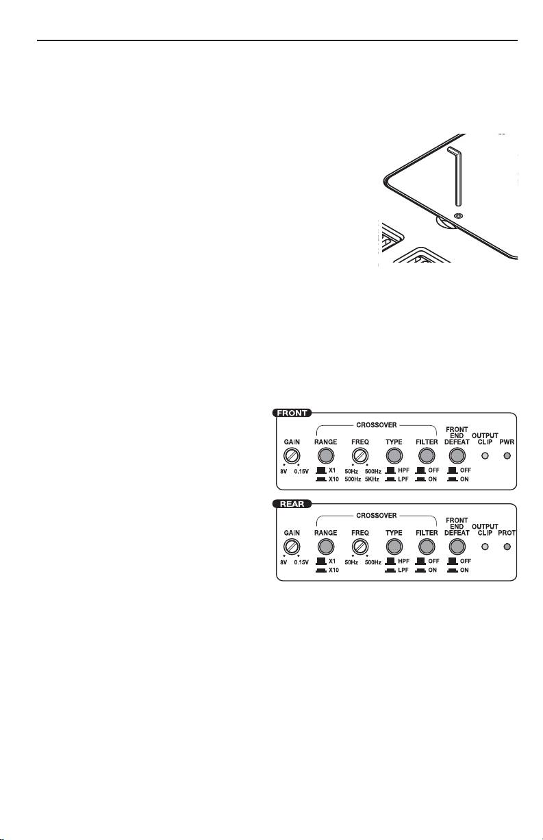
ADJUSTMENTS
Loosen the allen screw holding the small cover in place over the controls. Tilt
the cover up and away from the amplifier. After making adjustments, always
ensure the cover is in place to prevent accidental changes to the settings.
NOTE: Failure to follow these instructions may result in a loss of sonic
quality. This is caused by premature activation of the protection
circuitry to maintain the integrity of the amplifiers sensitive
components. The performance specifications listed in this manual
cannot be guaranteed under such conditions.
FRONT END DEFEAT
The front-end defeat switch is responsible for rerouting the signal around the
signal processing circuitry within the amplifier. This feature was designed for use with external processors to
provide the purest possible signal path through the amplifier.
With this configuration, the MB Quart R Series amplifiers are able to provide lower distortion and better
signal reproduction due to the reduction in the number of components in the signal path. Bypassing the
crossover will also eliminate the typical phase shift associated with the analog filter transform function. While
the Front End Bypass is turned on, all adjustments made to the gain or crossover will be bypassed.
CROSSOVER
Do the following individually for each channel.
Filter Switch
Placing the switch in the ON position (In Position)
sets the amplifier to the All Pass mode, preventing
any crossover adjustment, allowing all frequencies
to pass. Adjustments made to the Multiplier switch
or Frequency Adjuster are bypassed.
Frequency Switch
Placing the switch in the HPF position (In Position)
sets the amplifier to the High Pass mode, enabling
frequencies above the cut-off point to pass.
Placing the switch in the LPF position (Out Position)
sets the amplifier to the Low Pass mode, enabling
frequencies below the cut-off point to pass.
Multiplier Switch
This switch sets the multiplier for the crossover frequencies.
Placing the switch in the x10 position (In Position) sets the adjustable crossover frequency to 500-5KHz
(5000Hz).
Placing the switch in the x1 position (Out Position) sets the adjustable crossover frequency to 50-500Hz.
Frequency Adjustment
After setting the Frequency Switch and Multiplier Switch, use the Frequency Adjuster to set the desired cut-
off point.
Turning the adjuster counter-clockwise decreases the set frequency.
Turning the adjuster clockwise increases the set frequency.
Quick Setting: Decrease the crossover frequency all the way down. With the system playing, increase the crossover
frequency up slowly until the desired crossover point is achieved.
10

OPERA
TION
GAIN
Do the following individually for each channel.
Turning the adjuster clockwise decreases the set gain.
Turning the adjuster counter-clockwise increases the set gain.
1. To adjust the gain setting, turn the amplifier gains all the way down (clockwise).
2. Turn the source unit volume up until distortion is audible and then turn it down a bit until the distortion
is inaudible. This will be about all the way up on most source units.
3. Increase the amplifier gain setting until adequate volume is achieved or clipping is noted by the LED
indicators. Turn the gain down slightly if clipping is indicated.
Most quality source units do not distort, so the volume can be used at maximum setting.
NOTE: Best signal to noise and dynamic range are realized with the gain at minimum. Most users find
adequate gain and volume is achieved at about halfway in the adjustment range.
CAUTION: Avoid setting the amplifier gain very high as noise and distortion will increase
significantly.
NOTE: For a more in depth setting procedure, contact MB Quart Technical Support.
TROUBLESHOOTING
Amplifier Does Not Turn On
Possible Cause
Solution
The in-line fuse on battery positive
Check in-line fuse on battery positive cable. Replace if necessary.
cable is blown.
Poor ground connection
Verify that Ground connection is connected to clean metal on the
vehicle’s chassis. Repair/replace if necessary.
Poor power connection or power
Verify there is 10.5 - 15.5 Volts present at the positive battery and
outside acceptable range.
remote turn-on cable. Verify quality connections for both cables at
amplifier, stereo, and battery/fuseholder. Repair/replace if necessary.
No Sound Coming From Amplifier
Possible Cause
Solution
Poor RCA connections.
Verify good RCA input connections at source and amplifier. Check
entire length of cables for kinks, splices, etc. Test RCA inputs for
AC voltage with the source unit on. Repair/replace if necessary
Poor speaker connections
Use an ohm meter to check speaker wire integrity. Check entire
length of wires for kinks, splices, etc. Repair/replace if necessary.
Bad source unit
Connect RCA input from test source directly to amplifier input. If
this solves the problem, have the source unit repaired or replaced.
If not, have the amplifier checked by a qualified technician.
Speaker "Pop" When Amplifier Turns On
Possible Cause
Solution
Remote from source unit comes on too
Disconnect input signal to amplifier and turn amplifier on and off.
quickly.
If the noise is eliminated, connect the REM lead of amplifier to
source unit with a delay turn-on module
Poor remote power signal from source
Use a different 12 Volt source for REM lead of amplifier (i.e.
battery direct). If the noise is eliminated, use a relay to isolate the
amplifier from noisy turn-on output.
11

TROUBLESHOOTING
Excessive Engine Noise
Possible Cause
Solution
RCA cables too close to main power
Route all signal carrying wires (RCA, Speaker cables) away from
cables.
power and ground wires.
Bad component in the signal chain
Bypass any and all electrical components between the source and
the amplifier(s). Connect source directly to input of amplifier. If
noise goes away the unit being bypassed is the cause of the noise.
Poor ground connection at system
Remove existing ground wires for all electrical components.
components
Reground wires to different locations. Verify that grounding
location is clean, shiny metal free of paint, rust etc
Poor ground connection at battery
Add secondary ground cable from negative battery terminal to the
chassis metal or engine block of vehicle.
PROT (Protect) LED Comes On, Amplifier shuts down
Possible Cause
Solution
There is a short in the system
Turn the system off. Check connection to all components for possible
shorts. Check all wires and cables for kinks, splices, poor insulation,
etc. Repair/replace if necessary.
Amplifier has exceeded normal
Turn the system off and allow to cool. Verify adequate ventilation
operating temperature due to improper
around amplifier. Move the amplifier to a spot with better ventilation
ventilation.
if needed.
Speaker impedance too low
Check for proper speaker impedance, replace if needed.
Low battery voltage
Check that the vehicle charging system is maintaining proper voltage.
SPECIFICATIONS
MODEL- R Series RAA4200
Continuous Power Rating (RMS) - Measured at 14.4 Battery Volts
4 Load Per Channel 100 Watts x 4Ch and ≤ 1% THD+N
2 Load Per Channel 200 Watts x 4Ch and ≤ 1% THD+N
4 Load Bridged 400 Watts x 2Ch and ≤ 1% THD+N
Dimensions: Height 2.375" (6cm)
Width 11.5" (29.2cm)
Length 16.75" (42.5cm)
Amplifier Fuse Rating (Amp/Type) (3) 30A / ATC
Battery Fuse Rating (Amp) External (Not Supplied) 90A
Signal-to-Noise Ratio >80dB A-weighted (reference: 0dB = 2Vrms)
Crossover (Front and Rear) Selectable HPF/LPF or Off (High Pass / Low Pass or All Pass)
Crossover Slope 12dB/octave Butterworth
Crossover Frequency (Multiplier X1) variable from 50Hz to 500Hz
Crossover Frequency (Multiplier X10) variable from 500Hz to 5KHz
Frequency Response 0.25Hz to 100kHz (-3dB, 1watt)
Rated Bandwidth 20Hz to 20kHz
Signal Voltage Adjustment Range (RCA Input) Variable from 0.15V to 8V
Protection Shorted output, DC offset,
thermal, power supply over-current
Input Impedance 20k ohms
These specifications are Amplifier Power Standard CEA-2006 Compliant
Specifications subject to change without notice
12

LIMITED WARRANT
Y
INFORMA
TION
MB Quart Corporation offers a limited warranty on MB Quart products on the following terms:
Length of Warranty
R Series Amplifiers – 1 Year
Or, two (2) years warranty if installed by a Authorized MB Quart Dealer. Requires proof of purchase.
What is Covered
This warranty applies only to MB Quart products sold to consumers by Authorized MB Quart Dealers
in the United States of America or its possessions. Product purchased by consumers from an
Authorized MB Quart Dealer in another country are covered only by that country’s Distributor and
not by MB Quart.
Who is Covered
This warranty covers only the original purchaser of MB Quart product purchased from an Authorized
MB Quart Dealer in the United States. In order to receive service, the purchaser must provide MB
Quart with a copy of the receipt stating the customer name, dealer name, product purchased and
date of purchase.
Products found to be defective during the warranty period will be repaired or replaced
(with a product deemed to be equivalent) at MB Quart's discretion.
What is Not Covered
1. Damage caused by accident, abuse, improper operations, water, theft, shipping
2. Any cost or expense related to the removal or reinstallation of product
3. Service performed by anyone other than MB Quart or an Authorized MB Quart Service Center
4. Any product which has had the serial number defaced, altered, or removed
5. Subsequent damage to other components
6. Any product purchased outside the U.S.
7. Any product not purchased from an Authorized MB Quart Dealer
Limit on Implied Warranties
Any implied warranties including warranties of fitness for use and merchantability are
limited in duration to the period of the express warranty set forth above. Some states do not allow
limitations on the length of an implied warranty, so this limitation may not apply. No person is
authorized to assume for MB Quart any other liability in connection with the sale of the product.
How to Obtain Service
Contact the Authorized MB Quart Dealer you purchased this product from.
If you need further assistance, call 1-800-962-4412 for MB Quart Customer Service. You must
obtain an RA# (Return Authorization number) to return any product to MB Quart. You are
responsible for shipment of product to MB Quart.
EU Warranty
This product meets the current EU warranty requirements, see your Authorized dealer for details.
Ship to: Electronics
MB Quart
Warranty Repair Department
2055 E. 5th Street
Tempe, AZ 85281
RA#: _________________________
13

INTRODUCTION
Cher client,
Toutes nos félicitations pour avoir acheté un produit de la meilleure marque d'équipements audio pour automobile.
Chez MB Quart, nous sommes heureux que vous ayez choisi notre produit. Des années d'expertise en ingénierie, de
savoir-faire et d'essais poussés nous ont permis de créer une vaste gamme de produits capables de reproduire toute
la clarté et la richesse musicales que vous méritez.
Pour obtenir les meilleurs résultats, nous vous recommandons de faire installer votre nouvel appareil par un
Français
distributeur MB Quart agréé. Prenez soin de lire la garantie et conservez votre reçu ainsi que l'emballage d'origine
pour usage ultérieur.
Pour monter un excellent système, il ne suffit pas de posséder un super produit et d'assurer une installation qualifiée
compétente. Vous devez veiller à ce que votre installateur utilise des accessoires de qualité. Des câbles RCA et un
câble de haut-parleurs de mauvaise qualité peuvent affecter la performance et la reproduction sonore de votre
système. Utilisez ce qu'il y a de mieux lorsque vous effectuez ou faites effectuer l'installation. Insistez pour les avoir!
Après tout, votre nouveau système ne mérite rien de moins.
Pour obtenir une brochure gratuite sur les produits et accessoires MB Quart,
appelez aux États-Unis le 1-800-962-7757 ou faxez au 1-800-327-3777.
Pour tous les autres pays, appelez le +49 6261 638-0 ou faxez au +49 6261 638-129.
PRATIQUEZ UNE ÉCOUTE SANS RISQUESM
Une exposition continue à des niveaux de pression acoustique supérieurs à 100 dB peut
causer une perte d'acuité auditive permanente. Les systèmes audio de forte puissance pour
auto peuvent produire des niveaux de pression acoustique bien supérieurs à 130 dB. Faites
preuve de bon sens et pratiquez une écoute sans risques.
Si vous avez encore des questions à propos de ce produit, même après avoir lu ce manuel, contactez votre
distributeur agréé MB Quart. Si vous avez besoin d'aide, appelez-nous au 1-800-962-4412 (+49 6261 638 125 pour
l'Europe). Veuillez avoir les numéros de modèle et de série, ainsi que la date d'achat de l'appareil à portée de main
lorsque vous appelez.
Le numéro de série est indiqué sur l'extérieur de l'emballage. Cela permettra de vérifier votre garantie et de retrouver
votre amplificateur en cas de vol.
Numéro de série : ____________________________________________
Numéro de modèle : __________________________________________
TABLE DES MATIÈRES
Introduction. . . . . . . . . . . . . . . . . . . . . . . . . . . 2
Fonctionnement . . . . . . . . . . . . . . . . . . . . 10-11
Consignes de sécurité . . . . . . . . . . . . . . . . . . . . 3
Fonctions de réglage . . . . . . . . . . . . . . . . . . . . 10
Particularités techniques. . . . . . . . . . . . . . . . 4-5
Dérivation frontale. . . . . . . . . . . . . . . . . . . . . . 10
Installation. . . . . . . . . . . . . . . . . . . . . . . . . . 5-9
Filtre passif (X.Over). . . . . . . . . . . . . . . . . . . . . 10
Considérations concernant l'installation. . . . . 5
Gain. . . . . . . . . . . . . . . . . . . . . . . . . . . . . . . . . . 11
Emplacements de montage. . . . . . . . . . . . . . . . 6
Dépannage . . . . . . . . . . . . . . . . . . . . . . . . 11-12
Batterie et charge . . . . . . . . . . . . . . . . . . . . . . . 6
Spécifications. . . . . . . . . . . . . . . . . . . . . . . . . 12
Câblage du système. . . . . . . . . . . . . . . . . . . . . . 7
Informations sur la garantie limitée . . . . . . . . 13
REMARQUE : Consultez chaque section pour de plus amples informations.
2
Оглавление
- Français
- Français
- Français
- Français
- Français
- Français
- Français
- Français
- Français
- Français
- Français
- Français
- Español
- Español
- Español
- Español
- Español
- Español
- Español
- Español
- Español
- Español
- Español
- Español
- Deutsch
- Deutsch
- Deutsch
- Deutsch
- Deutsch
- Deutsch
- Deutsch
- Deutsch
- Deutsch
- Deutsch
- Deutsch
- Deutsch
- Italiano
- Italiano
- Italiano
- Italiano
- Italiano
- Italiano
- Italiano
- Italiano
- Italiano
- Italiano
- Italiano
- Italiano
- усский
- усский
