SIM2 MICO 50: Connections and setup 2.
Connections and setup 2.: SIM2 MICO 50
English
MiCO 50
9
Connections and setup 2.
Connecting the Projector to Other Devices
Before Setting Up
note
Before connecting, be sure to turn off both the projector and the devices. After making all
•
connections, turn on the projector and then the other devices.
Be sure to read the operation manuals of the devices to be connected before making connections.
•
This projector can be connected to
A VCR, Laser disc player or other video equipment.
n
A DVD player or DTV* decoder.
n
*DTV is the umbrella term used to describe the new digital television system in the United States.
A computer using HD 15-pin VGA to VGA cable (optional item, sold separately).
n
Connecting the Power Cord
Plug in the supplied power cord into the AC socket on the rear of the projector.
Press the power switch to turn on the projector.
Connecting to Video Equipment
Connecting to Video Equipment
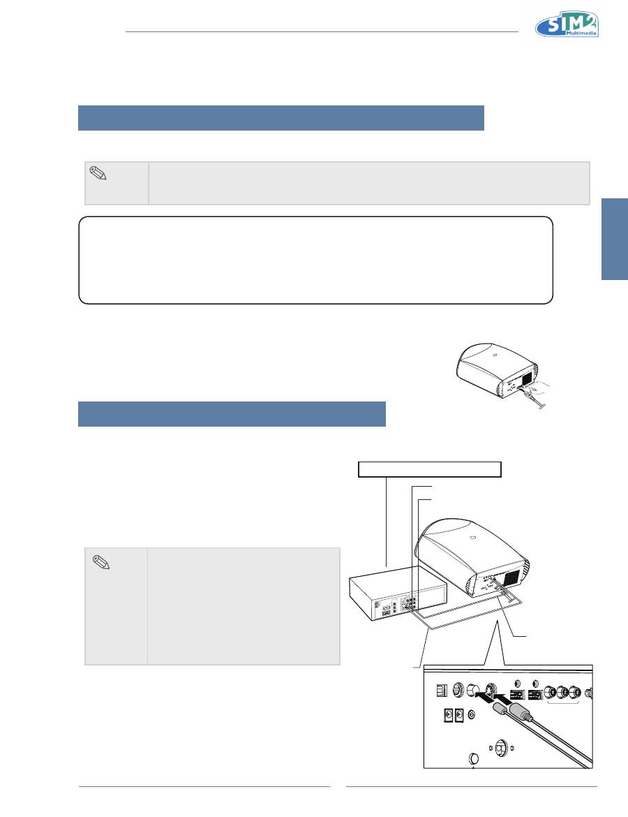
Using an s-Video or a Composite Video Cable
Using an S-Video or a Composite video cable, a VCR, laser
disc player or other video equipment can be connected to
S-Video or Composite input terminals.
note
The S-VIDEO terminal uses a video
•
signal system in which the picture is
separated into color and luminance
signals to realize a higher-quality
image. To view a higher-quality image,
use a commercially available S-Video
cable to connect the S-VIDEO terminal
on the projector and the S-Video output
terminal on the video equipment.
GR
HDMI 1
S-VIDEO
USB
12V
TRIG1
12V
TRIG2
WIRED REMOTE
COMPOSITE
RS-232
HDMI 2
COMPONENT
Pr
Pb
Y
To Video output terminal
To S-Video output terminal
VCR or other video equipment
Composite
video cable
(commercially
available)
S-Video cable
(commercially
available)
MiCO 50
10
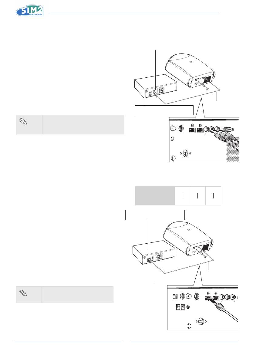
Connecting to Component Video
Equipment
Using a Component Cable
Use a component cable when connecting to the
Component terminal and component video equipment
such as DVD players and DTV* decoders.
*DTV is an umbrella term used to describe the new
digital television system in the United States.
GRAPHICS RGB
HDMI 1
S-VIDEO
COMPOSITE
WIRED REMOTE
HDMI 2
COMPONENT
Pr
Pb
Y
DVD player, BluRay player, or
DTV* decoder
To analog component
output terminal
Component cable
(commercially
available)
The component jack for a DVD and so forth may be
indicated with Y, CB or CR. Connect each jack as
shown below.
Projector
Y
Y
P
b
C
b
P
r
C
r
DVD player or
DTV decoder
note
When connecting the projector to the
•
video equipment in this way, select
“Component” for “Source” menu.
Connecting by Using a HDMI
to HDMI Cable
Use an HDMI to HDMI cable when connecting
HDMI video equipments such as DVD players to
HDMI 1 or 2 terminal.
GR
HDMI 1
S-VIDEO
COMPOSITE
USB
12V
TRIG1
12V
TRIG2
WIRED REMOTE
RS-232
HDMI 2
COMPONENT
Pr
Pb
Y
HDMI to HDMI cable
To HDMI output
terminal
1
Connect an hDMi to hDMi cable to
the projector.
2
Connect the above cable to the
video equipment.
note
Select the input signal type of
•
the video equipment.
DVD player, BluRay player, or
DTV* decoder
English
MiCO 50
11
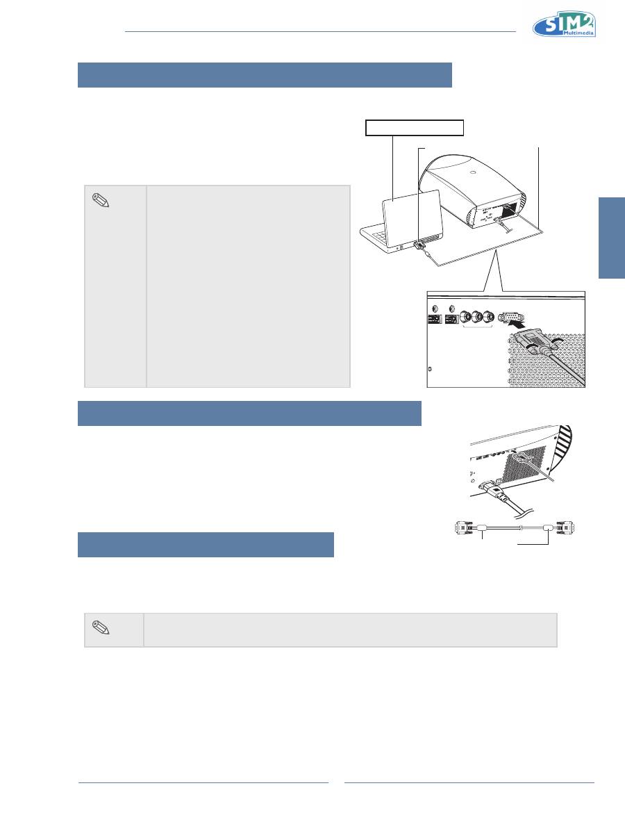
Connecting the Projector to a Computer
Connecting to a Computer
Connect the projector to the computer using the hD 15-pin
VgA to VgA cable.
Secure the connectors by tightening the thumbscrews.
•
note
See page 29 “Computer Compatibility
•
Chart” for a list of computer signals
compatible with the projector. Use with
computer signals other than those listed
may cause some functions not to work.
A Macintosh adaptor may be required for
•
use with some Macintosh computers.
Contact your nearest Authorized Service
Center or Dealer.
Depending on the computer you are
•
using, an image may not be projected
unless the signal output setting of the
computer is switched to the external
output. Refer to the computer operation
manual for switching the computer signal
output settings.
Connecting the Thumbscrew Cables
Connect the thumbscrew cable making sure that it fits correctly into the
n
terminal. Then, firmly secure the connectors by tightening the screws on
both sides of the plug.
Do not remove the ferrite core attached to the HD 15-pin VGA cable.
n
“Plug and Play” Function
This projector is compatible with VESA-standard DDC 1/DDC 2B. The projector and a VESA DDC compatible
n
computer will communicate their setting requirements, allowing for quick and easy setup.
Before using the “Plug and Play” function, be sure to turn on the projector first and the connected computer last.
n
note
The DDC “Plug and Play” function of this projector operates only when used in conjunction
•
with a VESA DDC compatible computer.
GRAPHICS RGB
HDMI 1
HDMI 2
COMPONENT
Pr
Pb
Y
To VGA output terminal
notebook Computer
HD 15-pin VGA to VGA cable
(sold separately)
Ferrite core
MiCO 50
12
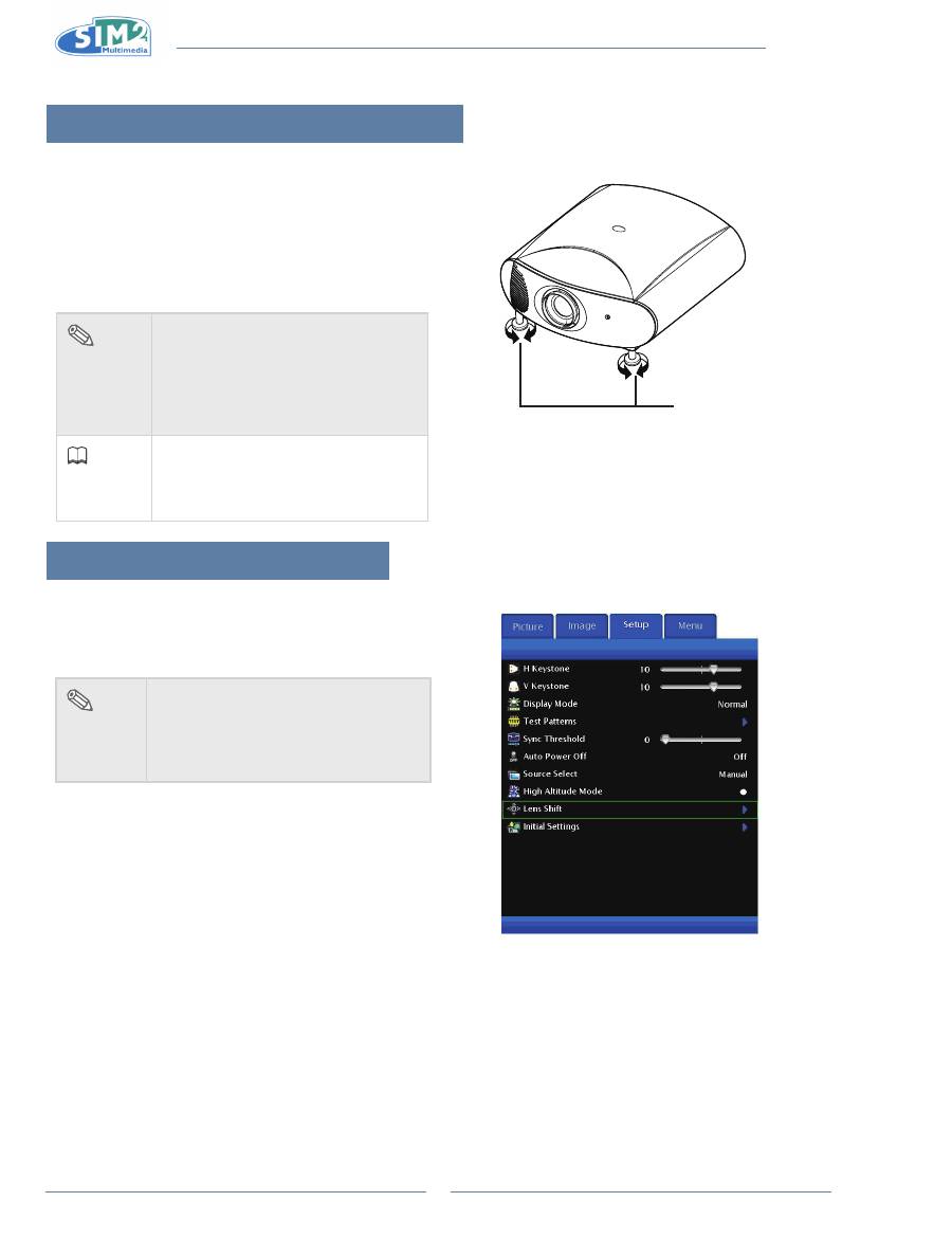
Using the Adjustment Feet
The height of the projector can be adjusted using the
•
adjustment feet when the surface the projector is
placed on is uneven or when the screen is slanted.
The projection of the image can be made higher by
•
adjusting the projector when it is in a location lower
than the screen.
If the screen is at an angle, the adjustment
•
feet can be
used to adjust the angle of the image.
Adjustment feet
note
When the height of the projector is
•
adjusted, the image may become
distorted (keystoned), depending on
the relative positions of the projector
and the screen. See page 24 for
details on keystone correction.
info
When lowering the projector, be
•
careful
not to get your finger caught
in the area between the adjustment
foot and the projector.
Using the lens shift
The height and width of the projected image can be
adjusted to be within the shift range of the lens by
motorized control at the lens shift on main menu.
note
In Setup menu, select Lens Shift
•
Function.
When moving the lens, if the projected
•
image remains still, turn the remote
key in reverse direction.
English
MiCO 50
13
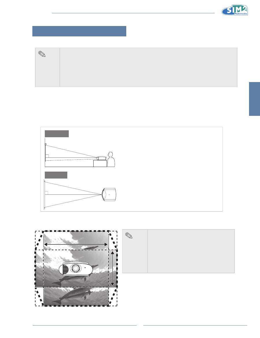
setting up the screen
Position the projector perpendicular to the screen with all feet flat and level to achieve an optimal image.
note
The projector lens should be centered in the middle of the screen. If the horizontal line passing
•
through the lens center is not perpendicular to the screen, the image will be distorted, making
viewing difficult.
For an optimal image, position the screen so that it is not in direct sunlight or room light. Light
•
falling directly on the screen washes out the colors, making viewing difficult. Close the
curtains and dim the lights when setting up the screen in a sunny or bright room.
A polarizing screen cannot be used with this projector.
•
standard setup (Front Projection)
Place the projector at the required distance from the screen according to
n
the desired picture size. (See page 14)
An Example of standard setup
90
Audience
90
side View
Top View
The distance from the screen to the projector may
•
vary depending on the size of the screen.
The default setting can be used, when placing the
•
projector in front of the screen. If the projected image
is reversed or inverted, readjust the setting to “Floor”
for “Orientation” in the “Image” menu.
Place the projector so that an imaginary horizontal
•
line that passes through the center of the lens is
perpendicular to the screen.
note
2D Lens Shift Ability:
Range: UP 60%, Down 25%,
•
Left 7.5%, Right 7.5%.
It is recommended that images be
•
projected onto the dashed line octagonal
area for fine image quality.
There is a tolerance of ±2.5% in the
•
formula above.
H
H
V
V
MiCO 50
14
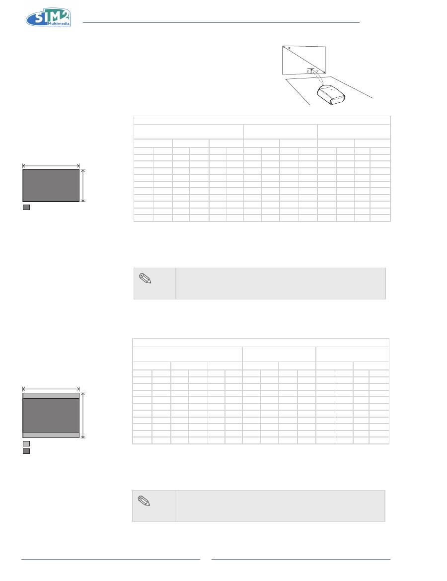
Screen Size and Projection Distance (Short
throw lens)
When using a wide screen
(16:9)
In case of displaying the 16:9
picture on the whole area of the
16:9 screen.
9
16
: Picture area
When using a normal screen
(4:3)
In case of setting the 16:9 picture
to the full horizontal width of the
4:3 screen.
3
4
: Screen area
: Picture area
Wide Screen 16:9
Screen Size
Throw Distance
Center of lens to edge of
image bottom
Diagonal size
Width
Height
Maximum
Minimum
Up
down
in
cm
in
cm
in
cm
ft
m
ft
m
in
cm
in
cm
300.0
762.0
261.5
664.1
147.1 373.6
45.1
13.7
32.2
9.8
14.7
37.4 -110.3 -280.2
250.0
635.0
217.9
553.5
122.6 311.3
37.6
11.4
26.8
8.2
12.3
31.1
-91.9 -233.5
200.0
508.0
174.3
442.8
98.1
249.1
30.0
9.2
21.4
6.5
9.8
24.9
-73.5 -186.8
150.0
381.0
130.7
332.1
73.5
186.8
22.5
6.9
16.1
4.9
7.4
18.7
-55.2 -140.1
133.0
337.8
115.9
294.4
65.2
165.6
20.0
6.1
14.3
4.3
6.5
16.6
-48.9 -124.2
106.0
269.2
92.4
234.7
52.0
132.0
15.9
4.9
11.4
3.5
5.2
13.2
-39.0
-99.0
100.0
254.0
87.2
221.4
49.0
124.5
15.0
4.6
10.7
3.3
4.9
12.5
-36.8
-93.4
92.0
233.7
80.2
203.7
45.1
114.6
13.8
4.2
9.9
3.0
4.5
11.5
-33.8
-85.9
84.0
213.4
73.2
186.0
41.2
104.6
12.6
3.8
9.0
2.7
4.1
10.5
-30.9
-78.5
72.0
182.9
62.8
159.4
35.3
89.7
10.8
3.3
7.7
2.4
3.5
9.0
-26.5
-67.2
The formula for screen size and projection distance
Y1 (Max.) = 0.15x
Y2 (Min.) = 0.107x
Z1 (Upper) = 0.049x
Z2 (Lower) = -0.367x
x : Screen size (in)
y : Projection distance (ft)
z : Distance from the lens center to the lower
edge of the image (in)
note
There is a tolerance of ±3% in the formula above.
•
Values with a minus (-) sign indicate the lens center is above
•
the bottom of the image.
Standard Screen 4:3
Screen Size
Throw Distance
Center of lens to edge of
image bottom
Diagonal size
Width
Height
Maximum
Minimum
Up
down
in
cm
in
cm
in
cm
ft
m
ft
m
in
cm
in
cm
300.0
762.0
240.0
609.6
180.0 457.2
41.4
12.6
29.5
9.0
18.0
45.7 -135.0 -342.9
250.0
635.0
200.0
508.0
150.0 381.0
34.5
10.5
24.6
7.5
15.0
38.1 -112.5 -285.8
200.0
508.0
160.0
406.4
120.0 304.8
27.6
8.4
19.7
6.0
12.0
30.5
-90.0 -228.6
150.0
381.0
120.0
304.8
90.0
228.6
20.7
6.3
14.8
4.5
9.0
22.9
-67.5 -171.5
133.0
337.8
106.4
270.3
79.8
202.7
18.3
5.6
13.1
4.0
8.0
20.3
-59.9 -152.0
106.0
269.2
84.8
215.4
63.6
161.5
14.6
4.5
10.4
3.2
6.4
16.2
-47.7 -121.2
100.0
254.0
80.0
203.2
60.0
152.4
13.8
4.2
9.8
3.0
6.0
15.2
-45.0 -114.3
92.0
233.7
73.6
186.9
55.2
140.2
12.7
3.9
9.0
2.8
5.5
14.0
-41.4 -105.2
84.0
213.4
67.2
170.7
50.4
128.0
11.6
3.5
8.3
2.5
5.0
12.8
-37.8
-96.0
72.0
182.9
57.6
146.3
43.2
109.7
9.9
3.0
7.1
2.2
4.3
11.0
-32.4
-82.3
The formula for screen size and projection distance
Y1 (Max.) = 0.138x
Y2 (Min.) = 0.098x
Z1 (Upper) = 0.06x
Z2 (Lower) = -0.45x
x : Screen size (in)
y : Projection distance (ft)
z : Distance from the lens center to the
lower edge of the image (in)
note
There is a tolerance of ±3% in the formula above.
•
Values with a minus (-) sign indicate the lens center is above
•
the bottom of the image.
English
MiCO 50
15
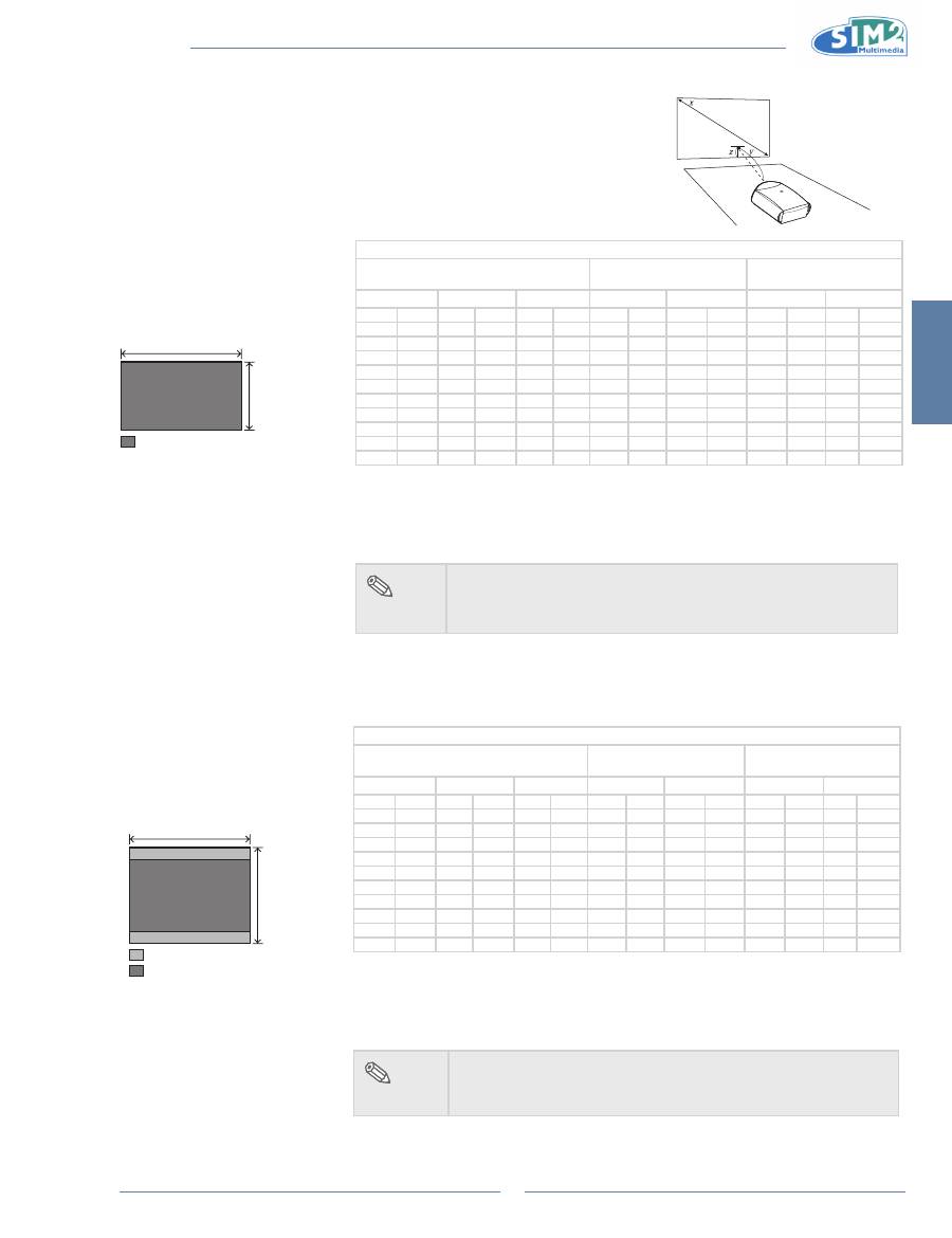
Screen Size and Projection Distance (Long
throw lens)
When using a wide screen
(16:9)
In case of displaying the 16:9
picture on the whole area of the
16:9 screen.
9
16
: Picture area
When using a normal screen
(4:3)
In case of setting the 16:9 picture
to the full horizontal width of the
4:3 screen.
3
4
: Screen area
: Picture area
Wide Screen 16:9
Screen Size
Throw Distance
Center of lens to edge of
image bottom
Diagonal size
WIdth
Height
Maximum
Minimum
Up
down
in
cm
in
cm
in
cm
ft
m
ft
m
in
cm
in
cm
300.0
762.0
261.5
664.1
147.1 373.6
89.4
27.2
45.3
13.8
14.7
37.4 -110.3 -280.2
250.0
635.0
217.9
553.5
122.6 311.3
74.5
22.7
37.7
11.5
12.3
31.1
-91.9 -233.5
200.0
508.0
174.3
442.8
98.1
249.1
59.6
18.2
30.2
9.2
9.8
24.9
-73.5 -186.8
150.0
381.0
130.7
332.1
73.5
186.8
44.7
13.6
22.6
6.9
7.4
18.7
-55.2 -140.1
133.0
337.8
115.9
294.4
65.2
165.6
39.6
12.1
20.1
6.1
6.5
16.6
-48.9 -124.2
106.0
269.2
92.4
234.7
52.0
132.0
31.6
9.6
16.0
4.9
5.2
13.2
-39.0
-99.0
100.0
254.0
87.2
221.4
49.0
124.5
29.8
9.1
15.1
4.6
4.9
12.5
-36.8
-93.4
92.0
233.7
80.2
203.7
45.1
114.6
27.4
8.4
13.9
4.2
4.5
11.5
-33.8
-85.9
84.0
213.4
73.2
186.0
41.2
104.6
25.0
7.6
12.7
3.9
4.1
10.5
-30.9
-78.5
72.0
182.9
62.8
159.4
35.3
89.7
21.5
6.5
10.9
3.3
3.5
9.0
-26.5
-67.2
The formula for screen size and projection distance
Y1 (Max.) = 0.298x
Y2 (Min.) = 0.151x
Z1 (Upper) = 0.049x
Z2 (Lower) = -0.367x
x : Screen size (in)
y : Projection distance (ft)
z : Distance from the lens center to the lower
edge of the image (in)
note
There is a tolerance of ±3% in the formula above.
•
Values with a minus (-) sign indicate the lens center is above
•
the bottom of the image.
Standard Screen 4:3
Screen Size
Throw Distance
Center of lens to edge of
image bottom
Diagonal size
WIdth
Height
Maximum
Minimum
Up
down
in
cm
in
cm
in
cm
ft
m
ft
m
in
cm
in
cm
300.0
762.0
240.0
609.6
180.0 457.2
82.1
25.0
41.5
12.7
18.0
45.7 -135.0 -342.9
250.0
635.0
200.0
508.0
150.0 381.0
68.4
20.8
34.6
10.6
15.0
38.1 -112.5 -285.8
200.0
508.0
160.0
406.4
120.0 304.8
54.7
16.7
27.7
8.4
12.0
30.5
-90.0 -228.6
150.0
381.0
120.0
304.8
90.0
228.6
41.0
12.5
20.8
6.3
9.0
22.9
-67.5 -171.5
133.0
337.8
106.4
270.3
79.8
202.7
36.4
11.1
18.4
5.6
8.0
20.3
-59.9 -152.0
106.0
269.2
84.8
215.4
63.6
161.5
29.0
8.8
14.7
4.5
6.4
16.2
-47.7 -121.2
100.0
254.0
80.0
203.2
60.0
152.4
27.4
8.3
13.8
4.2
6.0
15.2
-45.0 -114.3
92.0
233.7
73.6
186.9
55.2
140.2
25.2
7.7
12.7
3.9
5.5
14.0
-41.4 -105.2
84.0
213.4
67.2
170.7
50.4
128.0
23.0
7.0
11.6
3.5
5.0
12.8
-37.8
-96.0
72.0
182.9
57.6
146.3
43.2
109.7
19.7
6.0
10.0
3.0
4.3
11.0
-32.4
-82.3
The formula for screen size and projection distance
Y1 (Max.) = 0.273x
Y2 (Min.) = 0.138x
Z1 (Upper) = 0.06x
Z2 (Lower) = -0.45x
x : Screen size (in)
y : Projection distance (ft)
z : Distance from the lens center to the lower
edge of the image (in)
note
There is a tolerance of ±3% in the formula above.
•
Values with a minus (-) sign indicate the lens center is above
•
the bottom of the image.
MiCO 50
16
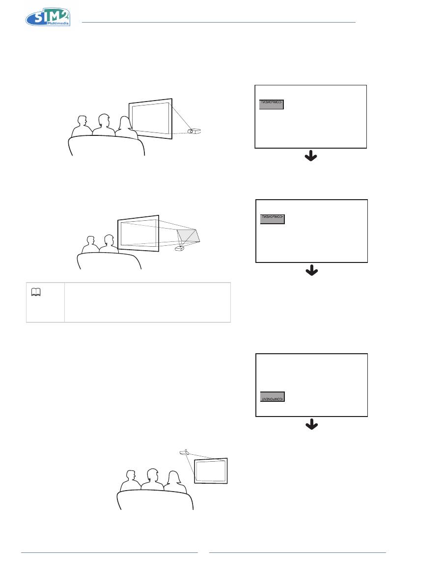
Projection from behind the screen
Projecting a Reversed/inverted image
Place a translucent screen between the projector and the audience.
n
Reverse the image by setting “Floor Rear” for “Orientation” in the
n
“Image” menu.
Projection using a mirror
Place a mirror (normal flat type) in front of the lens.
n
Reverse the image by setting “Floor Rear” for “Orientation” in the
n
“Image” menu, when the mirror is placed on the side where the
audience is.
info
When using a mirror, be sure to carefully position
•
both the projector and the mirror so that the light
does not shine into the eyes of the audience.
Ceiling-mount setup
It is recommended that you use the optional ceiling-mount bracket
n
for this installation.
Before mounting the projector, contact your nearest Authorized
n
Service Center or Dealer to obtain the recommended ceiling-
mount bracket (sold separately).
Be sure to adjust the position of the projector to match the
n
distance (Z) from the lens center position to the lower edge of the
image, when mounting the projector on the ceiling.
Invert the image by setting “Ceiling” for “Orientation” in the “Image”
n
menu.
When using the default setting.
q
On-screen Display
The image is reversed.
When using the default setting.
q
On-screen Display
The image is reversed.
When using the default setting.
q
On-screen Display
The image is reversed.
Оглавление
- Introduzione 1.
- Collegamenti e Impostazione 2.
- operazioni di base 3.
- Funzioni facili 4.
- appendice
- introduction 1.
- Connections and setup 2.
- Basic Operation 3.
- Easy to Use Functions 4.
- Appendix
- introduction 1.
- Branchements et réglages 2.
- Opérations de base 3.
- Fonctions faciles à utiliser 4.
- appendice
- einleitung 1.
- Verbindungen und einrichtung 2.
- Grundbedienung 3.
- Leicht bedienbare Funktionen 4.
- Anhang
- Introducción 1.
- Conexiones y configuración 2.
- Funcionamiento básico 3.
- Funciones de uso sencillo 4.
- apéndice
- Introdução 1.
- Ligações e instalação 2.
- Funções básicas 3.
- Funções fáceis de utilizar 4.
- Apêndice
- Введение 1.
- Подключения и настройка 2.
- Основные операции 3.
- Простые в использовании 4. функции
- Приложение
- 简介 1..
- 连接和设置 2..
- 基本操作 3..
- 简单易用的功能 4..
- 附录
