SIM2 MICO 50: Appendix
Appendix: SIM2 MICO 50
English
MiCO 50
27
Appendix
Maintenance
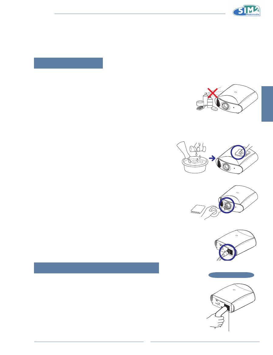
Cleaning the projector
Unplug the power cord before cleaning the projector.
n
Avoid using benzene or thinner, as these can damage the finish on the cabinet
n
and operation panel.
Do not use volatile agents such as insecticides on the projector.
n
Do not leave rubber or plastic objects in contact with the projector for long periods as they may damage the finish of
n
the projector.
Wipe off dirt gently with a soft flannel cloth
n
.
For hard-to-remove dirt, soak a cloth in a neutral detergent diluted with
n
water, wring the cloth well and then wipe the projector.
Strong cleaning detergents may discolor, warp or damage the coating
on the projector. Make sure to test on a small, inconspicuous area on
the projector before using.
Cleaning the lens
Use a commercially available blower or lens cleaning paper (for glasses and
n
camera lenses) for cleaning the lens. Do not use any liquid cleaning agents, as
they may wear off the coating film on the surface of the lens.
The surface of the lens is easily damaged, do not to scrape or hit the lens.
n
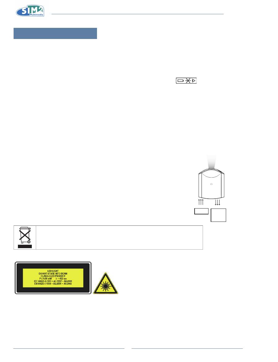
Cleaning the exhaust and intake vents
Use a vacuum cleaner to clean dust from the exhaust vent and the
n
intake vent.
Cleaning the Ventilation holes
This projector is equipped with ventilation holes to ensure the optimal
•
operating condition of the projector.
Periodically clean the ventilation holes by vacuuming it off with a
•
vacuum cleaner.
To clean the ventilation holes:
Turn off the power and unplug the power cord.
1.
Clean the dust off by placing the cleaner hose on the intake and
2.
exhaust ventilation holes.
Neutral detergent
diluted with water
Neutral
detergent
Cleaning
Paper
Side and Rear view
Ventilation holes
MiCO 50
28
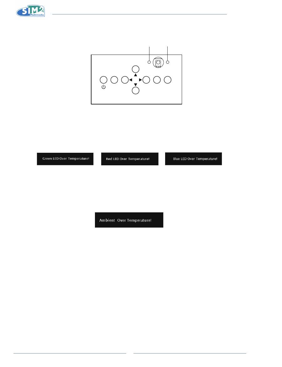
LED Over Temperature Alarm
The LED over temperature alarm on the control panel alerts you when the LED light source becomes too hot or the
peripheral is sultry.
If the Red and Blue LED illuminates during operation, the LED will shut off and the cooling fans will continue to run for
approximately 10 seconds. You should ensure that the airflow around the projector is sufficient, and ensure that the
projector has proper ventilation.
When the over temperature LED lights up, a warning also appears on the screen.
The over temperature alarm LED on the control panel alerts you when the ambient temperature
is too hot. If the LED blinks twice blue then one red during operation, the LEDs will shut off and
the cooling fans will continue to run for approximately 15 seconds. You should ensure that the
airflow around the projector is sufficient, and ensure that the projector has proper ventilation.
When the over temperature LED lights up, a warning also appears on the screen.
ESC
SOURCE
MENU
Red lED
Blue lED
English
MiCO 50
29
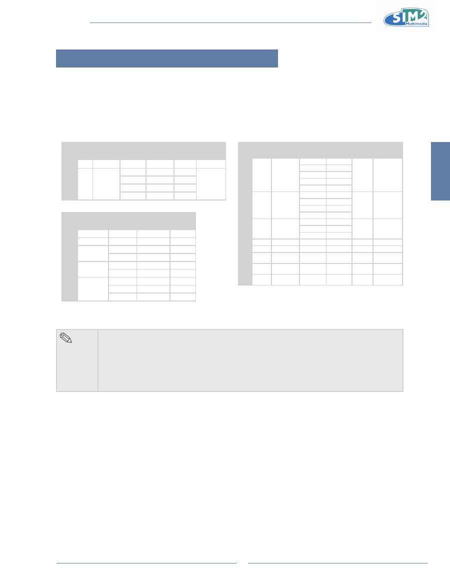
Computer Compatibility Chart
Multiple signal support
•
Horizontal Frequency: 25-91 kHz, Vertical Frequency: 24-85 Hz, Pixel Clock: 25-162 MHz
•
XGA, SXGA, UXGA compatible with advanced intelligent compression
•
The following is a list of modes that conform to VESA. However, this projector supports other signals that are not
•
VESA standards.
PC/
MAC/
WS
Resolution
Horizontal
Frequency
(kHz)
Vertical
Frequency
(Hz)
VESA
Standard
HDMI
Support
PC
DOS 720 x 400
31.5
70
P
VGA 640 x 480
31.5
60
P
37.9
72
P
37.5
75
P
43.3
85
P
Resolution
Horizontal
Frequency
(kHz)
Vertical
Frequency
(Hz)
VESA
Standard
HDMI
720 × 480
31.5
60
720 × 576
31.3
50
1280 × 720
45
60
37.5
50
1920 × 1080i
33.8
60
28.1
50
1920 x 1080p
27
24
56.3
50
67.5
60
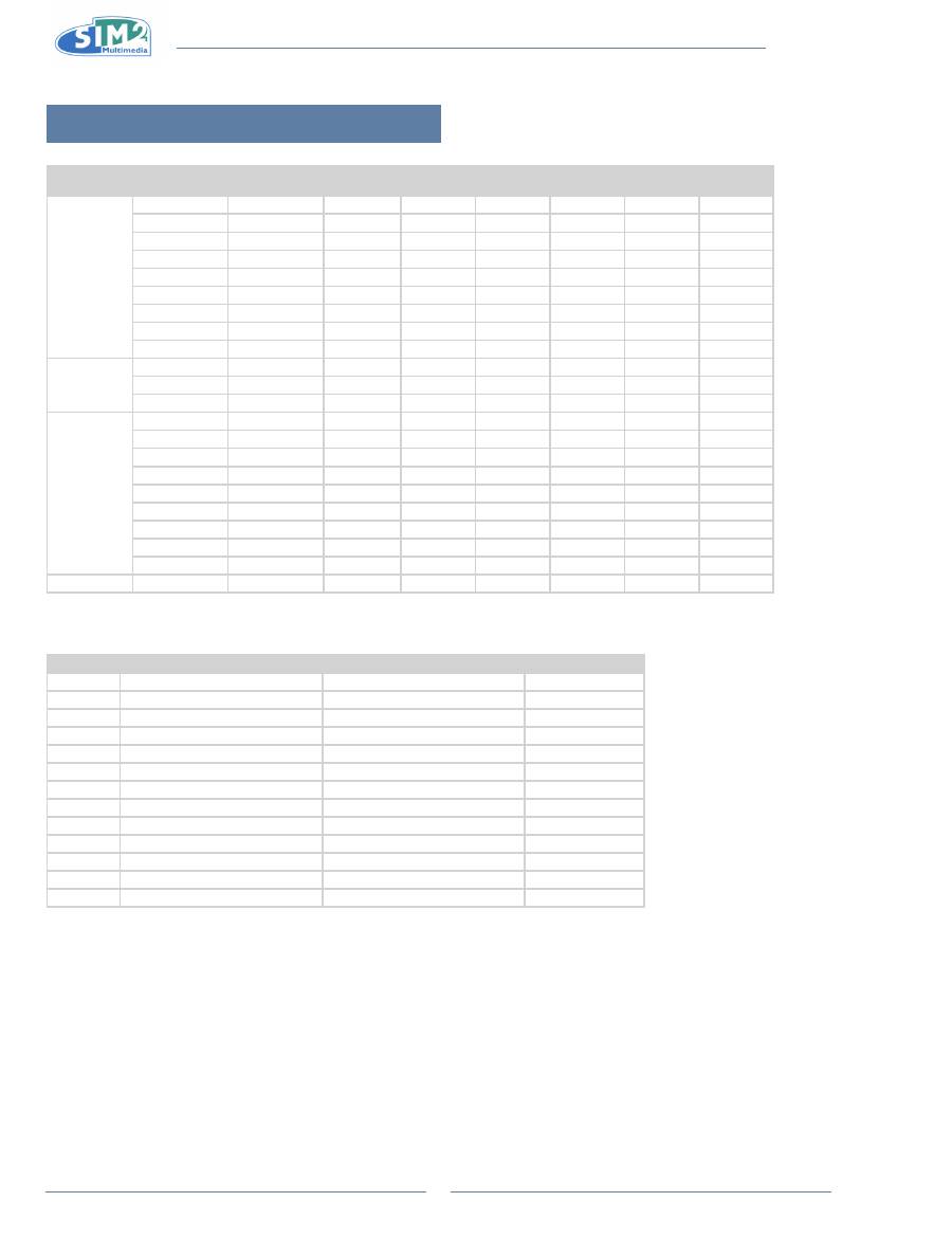
PC/
MAC/
WS
Resolution
Horizontal
Frequency
(kHz)
Vertical
Frequency
(Hz)
VESA
Standard
HDMI
Support
PC
SVGA
800 x 600
35.1
56
P
P
37.9
60
48.1
72
46.9
75
53.7
85
XGA
1024 x 768
48.4
60
P
P
56.5
70
60.0
75
68.7
85
SXGA 1280 x 1024
64.0
60
P
P
80.0
75
91.1
85
WSXGA 1680 x 1050
65.2
60
P
P
UXGA 1600 x 1200
75.0
60
P
P
MAC
13”
VGA
640 x 480
34.9
67
P
MAC
16”
SVGA
832 x 624
49.6
75
P
MAC
19”
XGA
1024 x 768
48.4
60
P
P
note
This projector may not be able to display images from notebook computers in simultaneous
•
(CRT/LCD) mode. Should this occur, turn off the LCD display and output the display data in
“CRT only” mode. Details on how to change display modes can be found in your notebook
computer’s operation manual.
When projecting video images of an interlace video signal, the intended image may not be
•
projected when using the RBG input. In such cases, use the Component input, S-Video input
or Composite input.
MiCO 50
30
Video Compatibility Chart
Resolution
H-Freq (kHz) V-Freq (Hz) Component
Support
S-Video
Support
Composite
Support
HDMI
Support
SD Video
NTSC
640x480i
15.7
59.94/60
P
P
P
PAL
768x576i
15.6
50
P
P
P
SECAM
768x576i
15.6
50
P
P
P
NTSC-4.43
P
P
P
PAL-M
P
P
P
PAL-N
P
P
P
NTSC-J
P
P
P
P
PAL-60
60
P
P
P
NTSC-50
50
ED TV
480p
720x480p
31.5
59.94/60
P
P
576p
720x576p
31.3
50
P
P
1035i/60
1920x1035i
33.8
60
P
P
HD TV
1080i/50
1920x1080i
28.1
50
P
P
1080i/60
1920x1080i
33.8
59.94/60
P
P
720p/50
1280x720p
37.5
50
P
P
720p/60
1280x720p
45.0
59.94/60
P
P
1080p/24
1920x1080p
27.0
24
P
P
1080p/25
1920x1080p
28.1
25
P
P
1080p/30
1920x1080p
33.8
30
P
P
1080p/50
1920x1080p
56.3
50
P
P
1080p/60
1920x1080p
67.5
60
P
P
HTPC
720p/48
1280x720p
36
48
P
1. Component supports signal formats are Y/Pb/Pr, Y/Cb/Cr.
2. VGA port support signal formats are RGBHV, RGsB, and RGBCs.
DTV
Signal
Horizontal Frequency (kHz)
Vertical Frequency (Hz)
HDMI Support
480i
15.7
60
480p
31.5
60
P
576i
15.6
50
576p
31.3
50
P
720p
45.0
60
P
720p
37.5
50
P
1080i
33.8
60
P
1080i
28.1
50
P
1080p
27
24
P
1080p
28.1
25
P
1080p
33.8
30
P
1080p
56.3
50
P
1080p
67.5
60
P
English
MiCO 50
31
Troubleshooting
Problem
Check
Projector does not start
Projector power cord is not plugged into the wall outlet.
Projector power switch does not turn on.
Remote control batteries have run out.
No picture
The selected input mode is wrong.
Cables may be incorrectly connected to the rear panel of the projector.
Power to the external connected device is off.
The video signal format of the video equipment is not set correctly.
faded
Picture adjustments are incorrectly set.
blurred
Adjust the focus
The projection distance exceeds the focus range.
Noise
(Component/VGA input only)
Perform "Frequency" adjustments also in component.
Perform "Phase" adjustments also in component.
green on COMPONENT
Change the input signal type of the video equipment.
dark / bright and whitish
Picture adjustments are incorrectly set.
too bright and whitish
Picture adjustments are incorrectly set.

MiCO 50
32
Product Specifications
item Description
Model No. 1080p DLP Front Projector
DLP Panel Panel size: 0.95''
Display method: DMD by Texas Instruments
Device method: Digital Light Processing (DLP™)
Resolution 1920 x 1080 pixels
Short Throw Lens 1-1.4 x zoom lens, F2.25~2.39, f= 30.63~42.93 mm
Long Throw Lens 1-1.85 x zoom lens, F2.2, f= 43.12~85.16 mm
Light source LED
Input Sources Video
HDMI x 2
YCbCr, YPbPr (Component Video) x 1
CVBS (Composite Video) x 1
S-Video x 1
PC x 1 (D-SUB 15 pins)
Control
RS-232 (For computer) x1
IR Receiver (For remote) x 2
12V trigger output x2
USB x 1
Wired remote x1
Computer Compatibility VGA,SVGA, XGA, WXGA, SXGA, WSXGA, UXGA
2D Lens Shift Ability Up 60%, Down 25%, Left 7.5%, Right 7.5%
Digital Keystone Correction 2D correction
Projection Lens Zoom and focus with motorized lens
Screen Size (Short Throw Lens) 65 ~ 200 inches
Screen Size (Long Throw Lens) 65 ~ 200 inches
Short Throw Ratio (16:9) 1.5 ~ 2.1 (with +/- 5% tolerance)
Long Throw Ratio (16:9) 2.1 ~ 3.9 (with +/- 5% tolerance)
Projection Distance in 100”
(Short Throw Lens) 3.3m ~ 4.6m
Projection Distance in 100”
(Long Throw Lens) 4.6m ~ 9.1m
Video Enhance 3D Y/C separation in Composite Video
Projection Method Floor,Ceiling,Rear,Rear Ceiling
OSD Control Projector keypad
IR remote control
Video System NTSC 3.58/NTSC 4.43/PAL/PAL-M/PAL-N/PAL 60/SECAM/
EDTV480p/EDTV 576p/HDTV 720p/HDTV 1080i/HDTV 1080p
Dimensions (Short Throw Lens) 540 mm x 235 mm x 641 mm (W x H x D)
Dimensions (Long Throw Lens) 540 mm x 235 mm x 641 mm (W x H x D)
Weight (Short Throw Lens) 25 kg (55 lb)
Weight (Long Throw Lens) 25 kg (55 lb)
Power Supply 100 ~ 240 V at 50/60 Hz
Power Consumption Maximum: 370W
Normal: less than 300W
Standby: less than 1W
Operating Temperature 5°C to 35°C
Humidity 20%~90% (non-condensing)
Specifications are subjected to change without notice.
English
MiCO 50
33
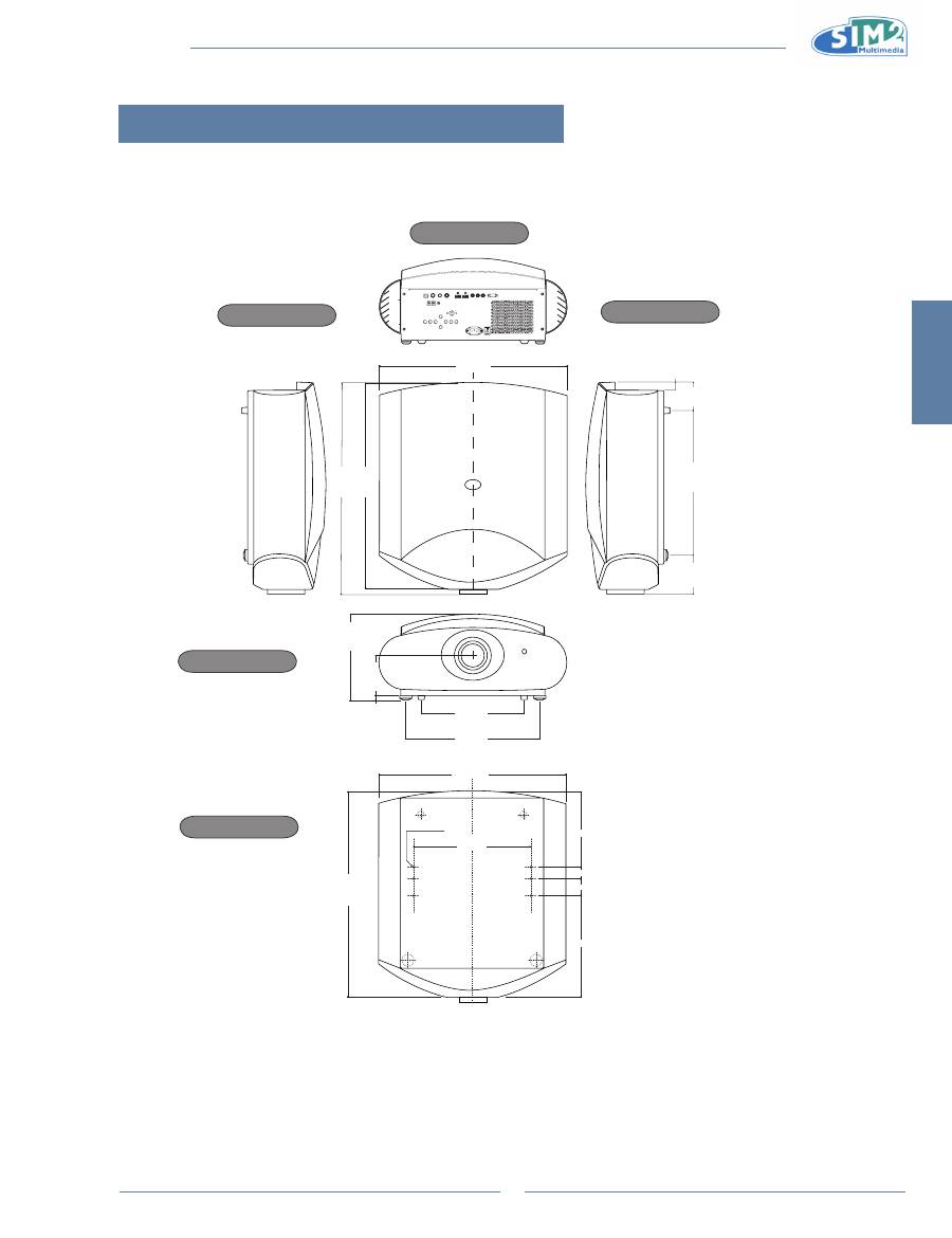
short Throw lens Dimension
540 mm
[21.3 inch]
640 mm [25.2 inch
]
631 mm [24.8 inch
]
24 mm [0.9 inch
]
296 mm
[11.7 inch]
370 mm
[14.6 inch]
116 mm [4.6 inch]
18 mm
[0.7 inch]
253 mm [10 inch]
540 mm
[21.3 inch]
631 mm [24.8 inch]
339 mm
[13.3 inch]
n˚ 6 screws M6
34 mm [1.3 inch]
197 mm [7.8 inch]
252 mm [9.9 inch]
53 mm [2.1 inch]
449 mm [17.7 inch
]
111 mm [4.4 inch
]
73mm [2.9 inch
]
Rear View
side View
side View
Front View
Bottom View
Units: mm (inch)
MiCO 50
34
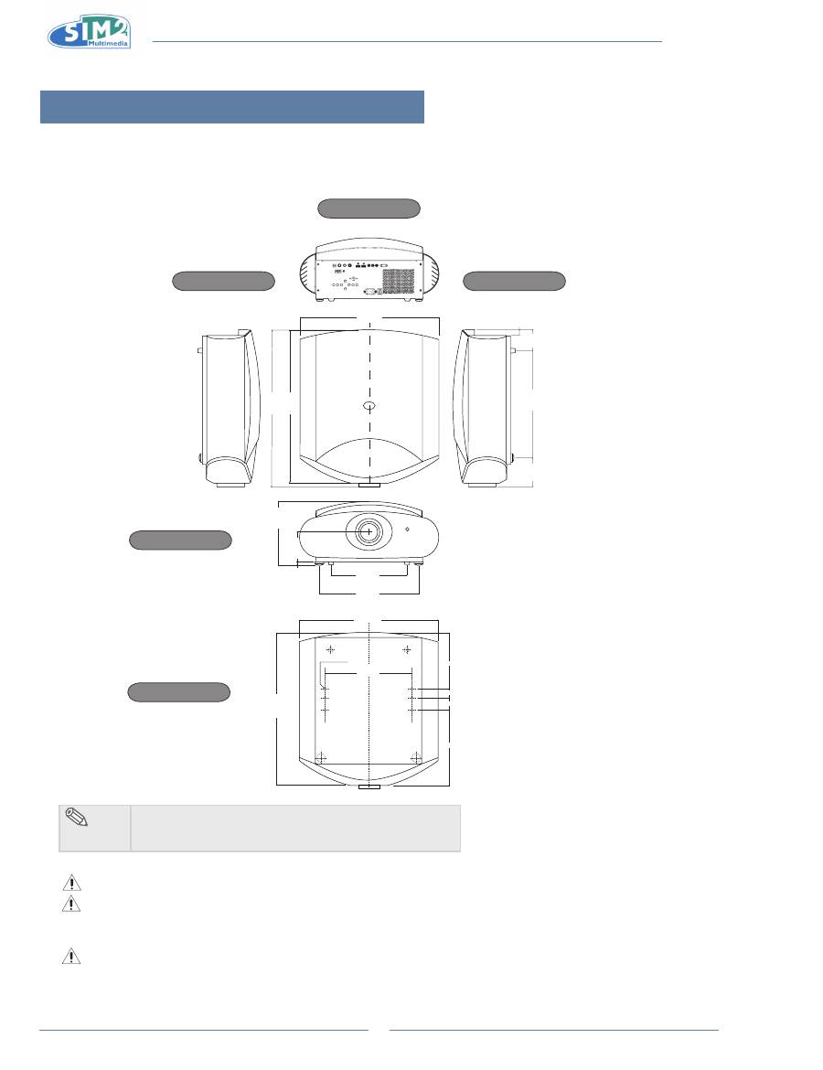
long Throw lens Dimension
540 mm
[21.3 inch]
638.6 mm [25.1 inch
]
631 mm [24.8 inch
]
24 mm [0.9 inch
]
296 mm
[11.7 inch]
370 mm
[14.6 inch]
116 mm [4.6 inch]
18 mm
[0.7 inch]
253 mm [10 inch]
540 mm
[21.3 inch]
631 mm [24.8 inch]
339 mm
[13.3 inch]
n˚ 6 screws M6
34 mm [1.3 inch]
197 mm [7.8 inch]
252 mm [9.9 inch]
53 mm [2.1 inch]
449 mm [17.7 inch
]
111 mm [4.4 inch
]
73mm [2.9 inch
]
Rear View
side View
side View
Bottom View
Front View
note
Your projector comes with 6 screws in the bottom.
•
Don't remove screws if you do not use ceiling mount.
•
Authorized technician should perform the installation only.
When using the ceiling mount bracket, the safety instructions provided with the bracket must be strictly
observed. Placed the projector at the desired distance from the screen: the size of the projected image
depends upon the distance between the lens and the screen and the zoom setting.
For ceiling/wall installation, by means of suspension bracket, carefully follow the instructions and
safety instructions recommended by the manufacturer in the bracket's literature.
Unit: mm (inch)
Français
MiCO 50
1
Préface
a PrOPOs DU ManUEL
Ce manuel a été conçu pour le projecteur frontal DEL 1080p DLP. L'exactitude des informations données dans le
présent document a été soigneusement vérifiée ; cependant, aucune garantie n'est donnée quant à la validité de son
contenu. Les informations contenues dans le présent document sont susceptibles de modification sans préavis.
COPYriGHT
© Copyright 2010
Ce document contient des informations propriétaires protégées par des droits d’auteur (copyright). Tous droits
réservés. Aucune partie de ce document ne peut être reproduite ou transmise sous aucune forme ou par quelque
moyen que ce soit, électronique ou mécanique, sans la permission préalable écrite du fabricant.
MarQUEs DE COMMErCE
Toutes les marques de commerce et les marques déposées sont la propriété de leurs propriétaires respectifs.
COnFOrMiTÉ À La FCC
Cet appareil est conforme à la section 15 du règlement de la FCC. L’utilisation de cet appareil est soumise aux deux
conditions suivantes :
(1) Cet appareil ne doit pas provoquer d’interférence nuisibles, et
(2) Cet appareil doit accepter toute interférence reçue, y compris celle qui entraînerait un fonctionnement inattendu.
DÉCLaraTiOn DE La COMMissiOn FÉDÉraLE DEs TÉLÉCOMMUniCaTiOns (FCC)
A l’issue des tests dont il a fait l’objet, cet appareil a été déclaré conforme aux normes des appareils numériques de
classe B conformément à la partie 15 du règlement de la FCC. Ces limites sont conçues pour fournir une protection
raisonnable contre les interférences nuisibles dans les installations résidentielles. Cet appareil génère, utilise et peut
émettre une énergie radio électrique, et s'il n'est pas installé et utilisé conformément aux instructions, il peut causer des
interférences préjudiciables aux communications radio. Cependant, aucune garantie n'est donnée qu'il ne causera pas
d’interférence dans une installation particulière. Si cet appareil produit des interférences nuisibles sur la réception de la
radio ou de la télévision, ce que vous pouvez facilement observer en éteignant et en rallumant l’appareil, nous vous
encourageons à prendre une ou plusieurs des mesures correctives suivantes :
Réorienter ou déplacer l’antenne de réception.
Augmenter la distance entre l'appareil et le récepteur.
Brancher l’appareil sur la prise d’un circuit auquel le récepteur n’est pas relié.
Consulter le revendeur ou un technicien radio/télévision qualifié ou obtenir de l'assistance.
Le symbole d'éclair avec une tête en forme de flèche à l’intérieur d’un triangle
équilatéral, est destiné à alerter l’utilisateur de la présence de tensions
dangereuses non isolées à l’intérieur du produit. Ces tensions peuvent être d’une
puissance suffisante pour constituer un risque d’électrocution pour les individus.
Le point d’exclamation à l’intérieur d’un triangle équilatéral a pour but d’avertir
l’utilisateur des points importants concernant l’utilisation et l’entretien
(maintenance) dans la documentation livrée avec l’appareil.
aVErTissEMEnT :
POUR REDUIRE LES RISQUES D’INCENDIE OU D’ELECTROCUTION,
NE PAS EXPOSER CE PRODUIT A LA PLUIE OU A L’HUMIDITE. DES TENSIONS
DANGEREUSES ELEVEES SONT PRESENTES A L'INTERIEUR DU BOITIER. NE PAS
OUVRIR LE BOITIER. POUR TOUTE REPARATION, VEUILLEZ VOUS ADRESSER
UNIQUEMENT A UN TECHNICIEN QUALIFIE.
Français
MiCO 50
2
avis
aVErTissEMEnT !
Afin de satisfaire les limites de la FCC, un cordon d'alimentation blindé est recommandé pour réduire le risque
•
d’interférence. Il est indispensable que vous n’utilisiez que le cordon d’alimentation fourni. Utilisez seulement des
câbles blindés pour connecter des appareils E/S à cet appareil. Vous êtes averti que toute modification ou
changement non expressément autorisée par l’entreprise qui doit garantir la conformité aux normes précitées peut
annuler la permission d’utilisation de l’appareil.
Source lumineuse puissante. Ne pas regarder directement le faisceau de lumière.
•
Faites particulièrement
attention avec les enfants et assurez-vous qu’ils ne regardent pas directement le faisceau de lumière.
Pour réduire le risque d'incendie et de choc électrique, ne pas exposer cet appareil à la pluie ou à l'humidité.
•
Certaines puces IC dans cet appareil peuvent contenir des données confidentielles ou des secrets commerciaux qui
•
restent la propriété de Texas Instruments. Par conséquent, vous ne pouvez pas copier, modifier, adapter, traduire,
distribuer, remonter, ré-assembler ou décompiler le contenu.
Les orifices de ventilation et les objets posés à côté peuvent devenir très chaud pendant l’utilisation de ce projecteur.
•
Ne les touchez pas jusqu’à ce qu’ils aient eu le temps de se refroidir.
aTTEnTiOn !
Pour réduire la fréquence des entretiens et garantir une image de la plus haute qualité, nous vous recommandons
•
d’utiliser ce projecteur dans un endroit sans fumée et sans poussière. Si vous utilisez ce projecteur dans des endroits
avec de la fumée ou de la poussière, le filtre et la lentille doivent être nettoyés régulièrement pour augmenter la durée
de vie du projecteur.
avertissement sur le ventilateur du projecteur
N’installez pas le projecteur dans un endroit fermé ou sans ventilation. Laissez
•
un espace d’au moins 50 cm entre les murs pour la circulation de l’air.
Veuillez lire attentivement ce manuel d’utilisation avant d’utiliser le projecteur.
•
Pour simplifier les rapports de vol ou de perte de votre Projecteur, écrivez le
•
numéro de série, indiqué au-dessous du projecteur. Avant de recycler la boîte,
vérifiez de nouveau la liste des éléments dans la boîte avec la liste "Contenu de
la boîte" à la page 5.
DEsCriPTiOn DEs sYMBOLEs
MisE aU rEBUT :
Ne jetez pas des appareils électriques ou électroniques avec les ordures ménagères
ou dans des poubelles municipales Dans les pays européens, vous devez utiliser des
points de collection pour le recyclage.
Mur
ou
bloc
air

Français
MiCO 50
3
Table des matières
Préface ...............................................................................1
Avis ....................................................................................2
introductio
1.
n
Contenu de la boîte
............................................................
5
Caractéristiques
.................................................................
5
Composants .......................................................................6
Projecteur (Vue de devant et vue de dessus)
..........6
Télécommande .......................................................6
Projecteur (vue de derrière)
....................................7
Utilisation de la télécommande ...........................................8
Portée de la télécommande ....................................8
Installation des piles................................................8
Branchements et réglage
2.
s
Connexion du projecteur à d’autres appareils
.....................9
Avant de faire des connexions ................................9
Branchement du cordon d'alimentation ...................9
Connexion à un appareil vidéo
...........................................9
Connexion à un appareil vidéo
................................9
Connexion à un appareil vidéo composante
.........10
Connexion en utilisant un câble HDMI à HDMI
......10
Connexion de ce projecteur à un ordinateur
.....................11
Connexion à un ordinateur
....................................11
Utilisation des vis à main des câbles
.................................11
Fonction « Plug & Play »
...................................................11
Utiliser les pieds réglables ................................................12
Utilisation du bouton d’ajustement de la lentille ................12
Installation de l’écran ........................................................13
Taille de l’écran et distance de projection
(Lentille de projection courte) ................................14
Taille de l’écran et distance de projection
(Lentille de projection longue) ...............................1
5
Projection de derrière l’écran
................................16
Opérations de bas
3.
e
Projection de l’image ........................................................17
Procédure basique
................................................17
Langue de l'affichage à l'écran
.........................................18
Utilisation du menu ...........................................................18
Sélection de menu (réglages)
...............................18
Réglage de l’image ...........................................................19
Réglage des préférences d’image ........................19
Fonctions faciles à utilise
4.
r
Image menu .....................................................................21
Menu de réglage
...............................................................24
Menu menu
......................................................................26
appendic
5.
e
Entretien ...........................................................................27
Nettoyage des trous de ventilation
....................................27
DEL d'avertissement de température ....................28
Tableau de compatibilité d’ordinateur ...............................29
Tableau de compatibilité vidéo..........................................30
Guide de dépannage
........................................................31
Caractéristiques techniques du produit
............................32
Dimensions lentille de projection courte ...........................33
Dimensions lntille de projection longue.............................34

MiCO 50
4
Оглавление
- Introduzione 1.
- Collegamenti e Impostazione 2.
- operazioni di base 3.
- Funzioni facili 4.
- appendice
- introduction 1.
- Connections and setup 2.
- Basic Operation 3.
- Easy to Use Functions 4.
- Appendix
- introduction 1.
- Branchements et réglages 2.
- Opérations de base 3.
- Fonctions faciles à utiliser 4.
- appendice
- einleitung 1.
- Verbindungen und einrichtung 2.
- Grundbedienung 3.
- Leicht bedienbare Funktionen 4.
- Anhang
- Introducción 1.
- Conexiones y configuración 2.
- Funcionamiento básico 3.
- Funciones de uso sencillo 4.
- apéndice
- Introdução 1.
- Ligações e instalação 2.
- Funções básicas 3.
- Funções fáceis de utilizar 4.
- Apêndice
- Введение 1.
- Подключения и настройка 2.
- Основные операции 3.
- Простые в использовании 4. функции
- Приложение
- 简介 1..
- 连接和设置 2..
- 基本操作 3..
- 简单易用的功能 4..
- 附录
