SIM2 MICO 50 – страница 3
Инструкция к Проектору SIM2 MICO 50

English
MiCO 50
3
Contents
Preface ...............................................................................1
Notice .................................................................................2
introductio
1.
n
Package Contents ..............................................................5
Features .............................................................................5
Components .......................................................................6
Projector (Front and Top View) ................................6
Remote Control.......................................................6
Projector (Rear View) ..............................................7
Using the Remote Control ..................................................8
Available Range of the Remote Control ..................8
Inserting the Batteries .............................................8
Connections and setu
2.
p
Connecting the Projector to Other Devices .........................9
Before Setting Up....................................................9
Connecting the Power Cord ....................................9
Connecting to Video Equipment .........................................9
Connecting to Video Equipment ..............................9
Connecting to Component Video Equipment ........10
Connecting by Using a HDMI to HDMI Cable ........10
Connecting the Projector to a Computer ...........................11
Connecting to a Computer ....................................11
Connecting the Thumbscrew Cables ................................11
“Plug and Play” Function ..................................................11
Using the Adjustment Feet................................................12
Using the Lens Shift..........................................................12
Setting up the Screen .......................................................12
Screen Size and Projection Distance
(Short throw lens)..................................................14
Screen Size and Projection Distance
(Long throw lens) ..................................................15
Projection from behind the screen.........................16
Basic Operatio
3.
n
Image Projection ..............................................................17
Basic Procedure ...................................................17
On-screen Display Language ...........................................18
Using the Menu Screen ....................................................18
Menu Selections (Adjustments) ............................18
Adjusting the Picture.........................................................19
Adjusting Image Preferences ................................19
Easy to Use Function
4.
s
Image menu .....................................................................21
Setup menu ......................................................................24
Menu menu ......................................................................26
Appendi
5.
x
Maintenance .....................................................................27
Cleaning the Ventilation Holes ..........................................27
LED Over Temperature Alarm ...............................28
Computer Compatibility Chart ..........................................29
Video Compatibility Chart .................................................30
Troubleshooting ...............................................................31
Product Specifications
......................................................32
Short Throw Lens Dimension ...........................................33
Long Throw Lens Dimension ............................................34

MiCO 50
4
English
MiCO 50
5
introduction 1.
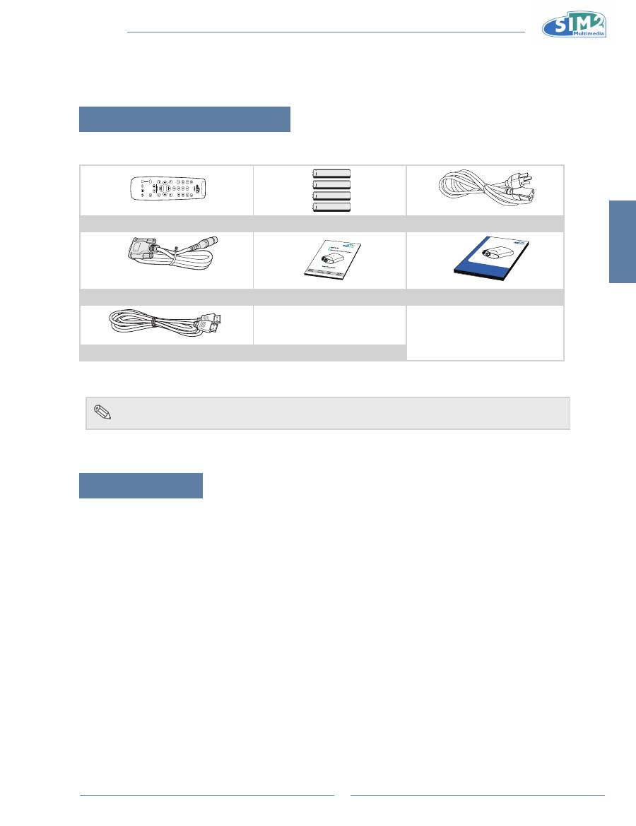
Package Contents
Open the package and ensure that you have the following items:
LIG
H
T
F1
Z
O
O
M
FO
C
U
S
F2
Remote control
Four “AAA” size batteries
Power cord (By country)
C3X Lu
mis HO
ST
User an
d insta
llation m
anual
MICO 50
User an
d insta
llation m
anual
RS232 cable
Quick Guide
User’s Manual
Optional:
Ceiling mount package
•
HDMI to HDMI cable (3M)
note
Some of the cables may not be available depending on the region. Please check with
•
your nearest Authorized Dealer.
If anything is missing or appears damaged, contact your dealer immediately.
Features
0.95" 1080p single chip DMD™ DarkChip4.
•
newly developed lVDs chip.
•
high color purity and high brightness thanks to lED light source.
•
Enhanced i/p conversion algorithm.
•
Extensive improvements on the jagged edges or slanted lines in moving images.
•
improved Edge Up-scaling.
•
As a result of reducing jagged edges and flickering when up-scaling edges of slanted lines, even signals
•
not reaching a panel resolution of 480i/p can be projected by converting them to 1920X1080 resolution
images.
improved Film Mode Function.
•
3:2 pull down enhancement for 480i and 2:2 for 576i signals, but HDTV 1080i signals as well.
•
Use of a hDMi/hDCP terminal enables all processes from input to signal processing and projection to be
•
performed digitally, resulting in the realization of all-digital projection without any data loss due to
analog conversion. This also supports the building of home theaters using hTPC.
lighting system: luminus Phlatlight PT120 R/g/B lEDs.
•
lED life: around 30.000 hours.
•
new DynamicBlack technology.
•
Contrast ratio up to 100.000:1 (with DynamicBlack).
•
Luminance over 800 ANSI Lumens (common Bightness figure around 25% more than luminance one).
•
2 lenses available: short throw ratio (T1 : 1.5 –2.1 :1) and long throw ratio (T2: 2.1 –3.9 :1).
•
Horizontal and vertical motorized lens shift.
•
low power consumption in standby mode (< 1W).
•
MiCO 50
6
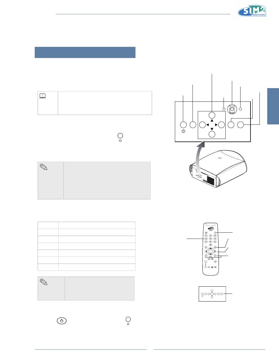
Components
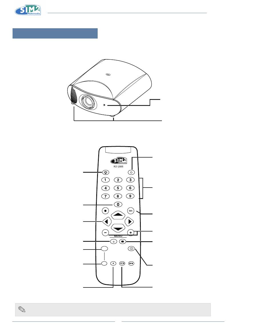
Projector (Front and Top View)
Adjustment feet
Remote control sensor
Remote Control
LIGHT
F1
ZOOM
FOCUS
F2
Power OFF button
For turning the power off.
p
/
q
/
t
/
u
Browse through OSD menus and
parameter settings.
MEnU +/-
Switches on the OSD and browse through its
pages.
info
Display information on the selected sources
and projector status.
Zoom
Selects lens
zoom adjustment.
Auto
Automatically optimizes the projected image
on the Graphics RGB source.
Focus
Set the lens to focus.
EsC button
Disables the OSD.
Backlighting
Backlights the keys on the remote control.
Key 0
Switches the panel on from Standby.
Keys 1-7
Selects the sources directly.
(switch the panel on from standby)
1 Composite
2 S-VIDEO
3 COMPONENT
4 GRAPHICS RGB
5 HDMI 1
6 HDMI 2
7 SCART
Memories
Opens the Memory management menu.
Aspect
Selects the images aspect ratio.
Freeze
Freezes/unfreezes a moving picture.
note
To use SCART input mode, first ensure that the SCART-to-RCA cable is connected and
•
SCART is set enabled via Source menu.
English
MiCO 50
7
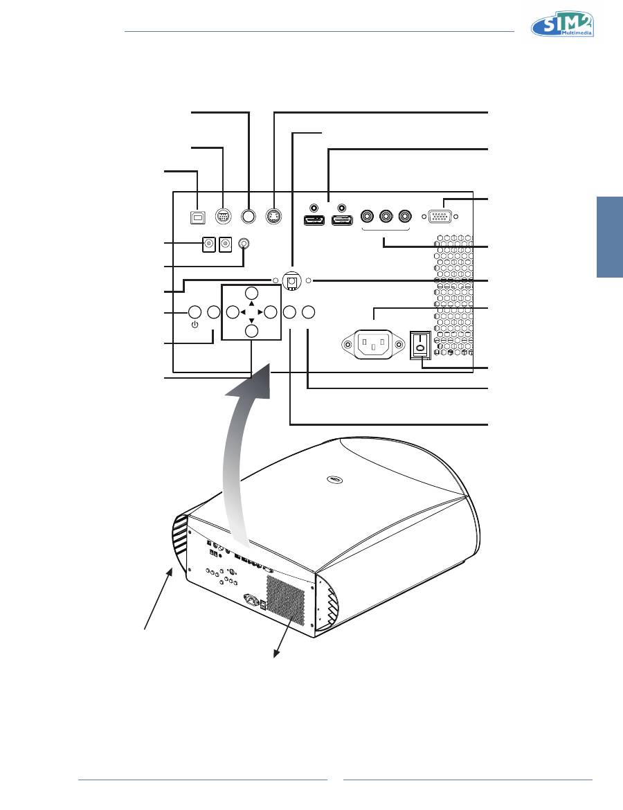
Projector (Rear View)
GRAPHICS RGB
HDMI 1
S-VIDEO
COMPOSITE
ESC
SOURCE
MENU
100-240 V / 50-60 Hz
USB
12V
TRIG1
12V
TRIG2
WIRED REMOTE
RS-232
HDMI 2
COMPONENT
Pr
Pb
Y
Exhaust vent
Remote control sensor
Component
Terminals for YPbPr/
YCbCr
AC socket
100~240V AC, 50/60Hz
Wired Remote
Terminal for wired
remote control
12V Trigger
Terminals for screen
controlling
Rs-232C terminal
Command control
UsB
B type terminal for
service port
s-Video
Terminals for connecting
S-Video
hDMi
Terminals for connecting
HDMI
PC
Terminal for connecting PC
RGB signals
Composite
Terminals for connecting
Composite
Air inlet
p
/
q
/
t
/
u
Browse through the
OSD menus and set
parameters.
source
Open the input selection
menu.
EsC
Disables the OSD.
Menu
Press to open the
OSD menu.
Power
Power switch
Red lED
Standby
Blue lED
Power ON
MiCO 50
8
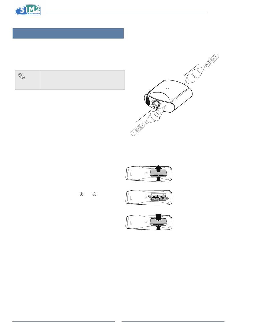
Using the Remote Control
Available Range of the Remote Control
The remote control can be used to control the projector within
n
the ranges shown in the illustration.
note
The signal from the remote control
•
can be
reflected by the screen. Remote control
signal may vary according to usage.
When using the remote control:
Be sure not to drop it, or expose it to moisture or high
•
temperature.
The remote control may malfunction under a fluorescent
•
lamp. If that occurs, move the projector away from the
fluorescent lamp.
Inserting the Batteries
The batteries (four “AAA” size) are included in the package.
1
Press down the tab on the cover
and pull the cover towards the
direction of the arrow.
2
insert the included batteries.
Insert the batteries making sure the
polarities correctly match the and
marks inside the battery
compartment.
3
insert the lower tab of the cover
into the opening, and press down
the cover until it clicks in place.
30°
23'(7 m)
LIG
HT
F1
ZO
O
M
FO
CU
S
F2
30°
30°
23'(7 m)
LI
GH
T
F1
ZO
O
M
FO
CU
S
F2
25°
English
MiCO 50
9
Connections and setup 2.
Connecting the Projector to Other Devices
Before Setting Up
note
Before connecting, be sure to turn off both the projector and the devices. After making all
•
connections, turn on the projector and then the other devices.
Be sure to read the operation manuals of the devices to be connected before making connections.
•
This projector can be connected to
A VCR, Laser disc player or other video equipment.
n
A DVD player or DTV* decoder.
n
*DTV is the umbrella term used to describe the new digital television system in the United States.
A computer using HD 15-pin VGA to VGA cable (optional item, sold separately).
n
Connecting the Power Cord
Plug in the supplied power cord into the AC socket on the rear of the projector.
Press the power switch to turn on the projector.
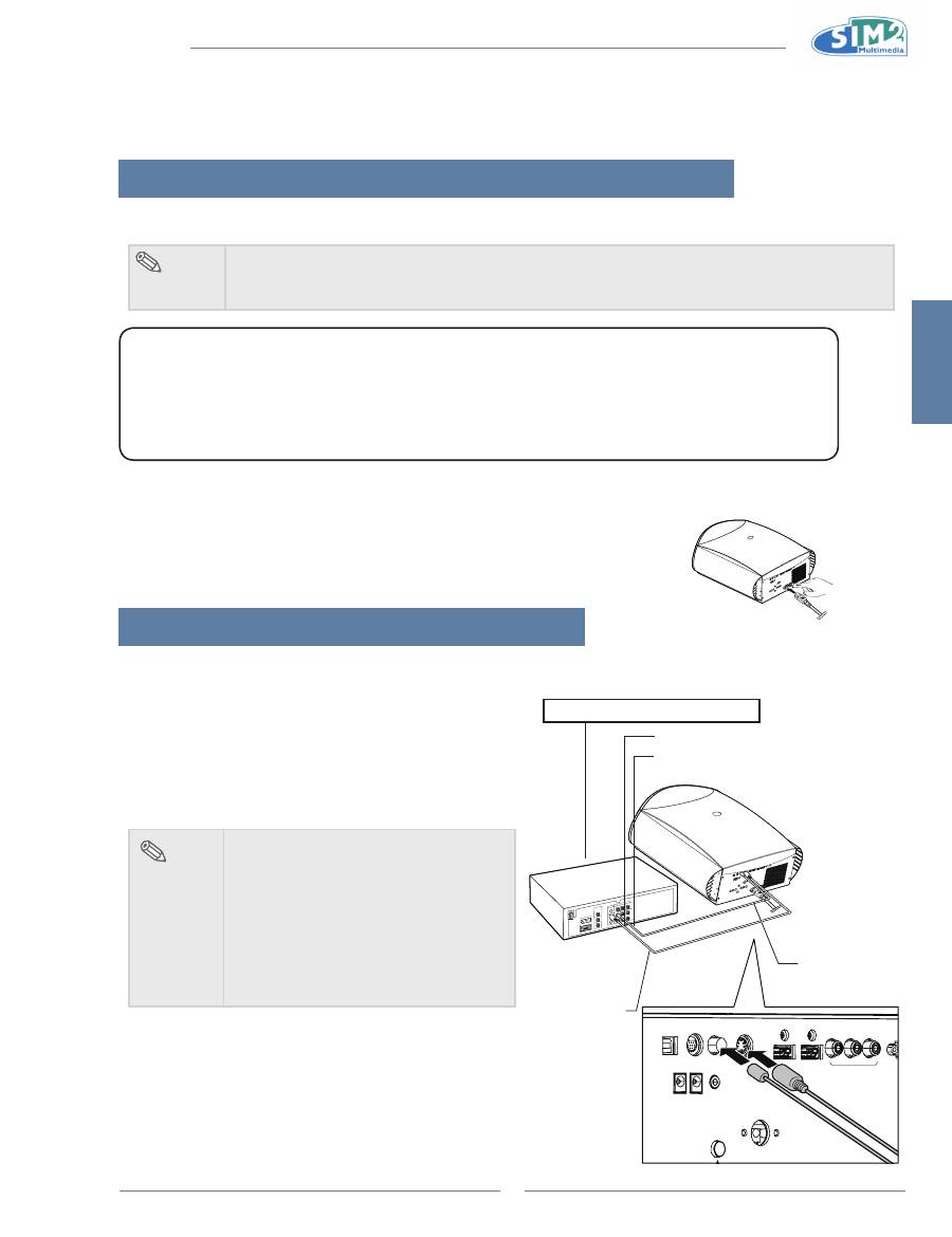
Connecting to Video Equipment
Connecting to Video Equipment
Using an s-Video or a Composite Video Cable
Using an S-Video or a Composite video cable, a VCR, laser
disc player or other video equipment can be connected to
S-Video or Composite input terminals.
note
The S-VIDEO terminal uses a video
•
signal system in which the picture is
separated into color and luminance
signals to realize a higher-quality
image. To view a higher-quality image,
use a commercially available S-Video
cable to connect the S-VIDEO terminal
on the projector and the S-Video output
terminal on the video equipment.
GR
HDMI 1
S-VIDEO
USB
12V
TRIG1
12V
TRIG2
WIRED REMOTE
COMPOSITE
RS-232
HDMI 2
COMPONENT
Pr
Pb
Y
To Video output terminal
To S-Video output terminal
VCR or other video equipment
Composite
video cable
(commercially
available)
S-Video cable
(commercially
available)
MiCO 50
10
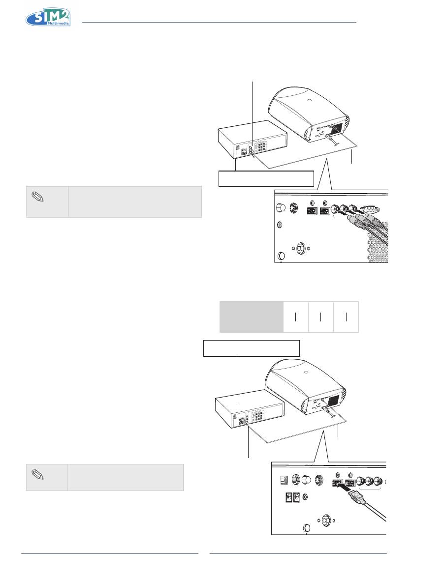
Connecting to Component Video
Equipment
Using a Component Cable
Use a component cable when connecting to the
Component terminal and component video equipment
such as DVD players and DTV* decoders.
*DTV is an umbrella term used to describe the new
digital television system in the United States.
GRAPHICS RGB
HDMI 1
S-VIDEO
COMPOSITE
WIRED REMOTE
HDMI 2
COMPONENT
Pr
Pb
Y
DVD player, BluRay player, or
DTV* decoder
To analog component
output terminal
Component cable
(commercially
available)
The component jack for a DVD and so forth may be
indicated with Y, CB or CR. Connect each jack as
shown below.
Projector
Y
Y
P
b
C
b
P
r
C
r
DVD player or
DTV decoder
note
When connecting the projector to the
•
video equipment in this way, select
“Component” for “Source” menu.
Connecting by Using a HDMI
to HDMI Cable
Use an HDMI to HDMI cable when connecting
HDMI video equipments such as DVD players to
HDMI 1 or 2 terminal.
GR
HDMI 1
S-VIDEO
COMPOSITE
USB
12V
TRIG1
12V
TRIG2
WIRED REMOTE
RS-232
HDMI 2
COMPONENT
Pr
Pb
Y
HDMI to HDMI cable
To HDMI output
terminal
1
Connect an hDMi to hDMi cable to
the projector.
2
Connect the above cable to the
video equipment.
note
Select the input signal type of
•
the video equipment.
DVD player, BluRay player, or
DTV* decoder
English
MiCO 50
11
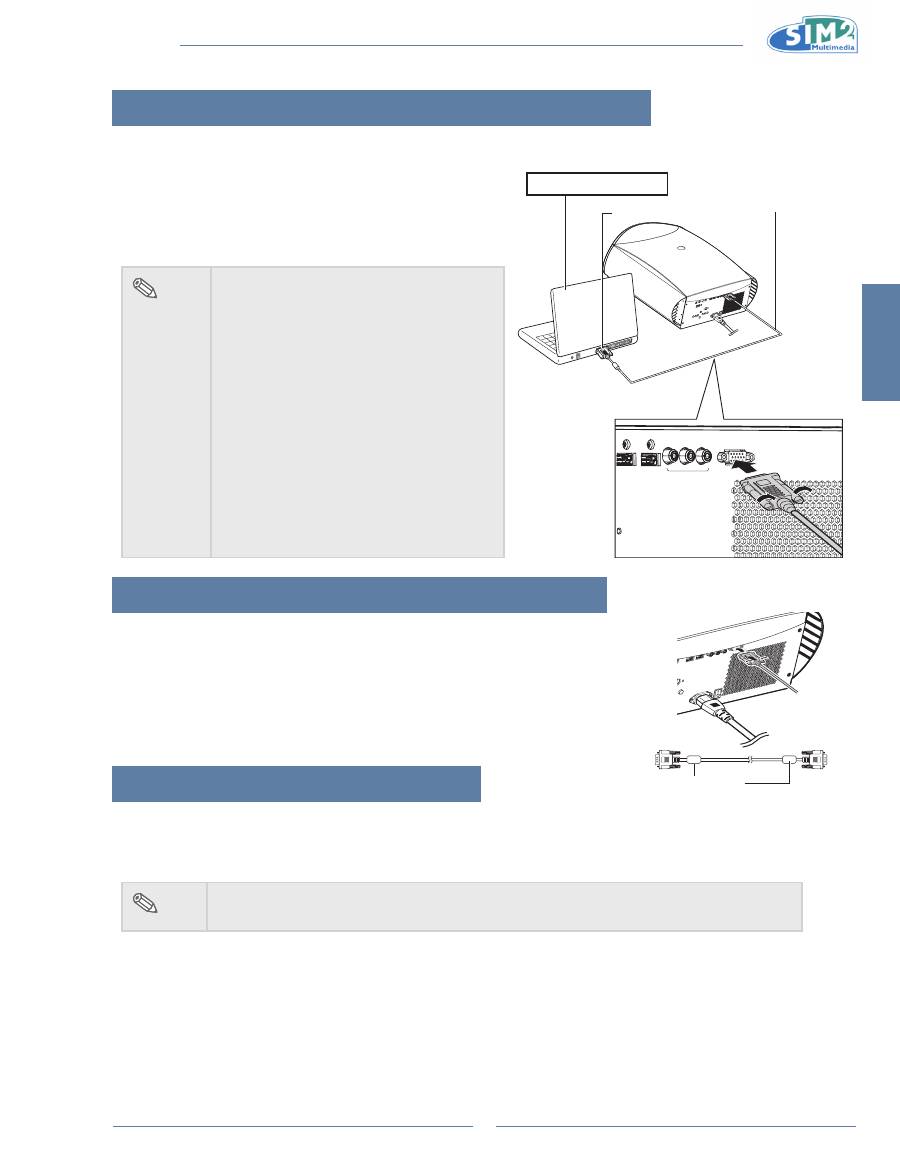
Connecting the Projector to a Computer
Connecting to a Computer
Connect the projector to the computer using the hD 15-pin
VgA to VgA cable.
Secure the connectors by tightening the thumbscrews.
•
note
See page 29 “Computer Compatibility
•
Chart” for a list of computer signals
compatible with the projector. Use with
computer signals other than those listed
may cause some functions not to work.
A Macintosh adaptor may be required for
•
use with some Macintosh computers.
Contact your nearest Authorized Service
Center or Dealer.
Depending on the computer you are
•
using, an image may not be projected
unless the signal output setting of the
computer is switched to the external
output. Refer to the computer operation
manual for switching the computer signal
output settings.
Connecting the Thumbscrew Cables
Connect the thumbscrew cable making sure that it fits correctly into the
n
terminal. Then, firmly secure the connectors by tightening the screws on
both sides of the plug.
Do not remove the ferrite core attached to the HD 15-pin VGA cable.
n
“Plug and Play” Function
This projector is compatible with VESA-standard DDC 1/DDC 2B. The projector and a VESA DDC compatible
n
computer will communicate their setting requirements, allowing for quick and easy setup.
Before using the “Plug and Play” function, be sure to turn on the projector first and the connected computer last.
n
note
The DDC “Plug and Play” function of this projector operates only when used in conjunction
•
with a VESA DDC compatible computer.
GRAPHICS RGB
HDMI 1
HDMI 2
COMPONENT
Pr
Pb
Y
To VGA output terminal
notebook Computer
HD 15-pin VGA to VGA cable
(sold separately)
Ferrite core
MiCO 50
12
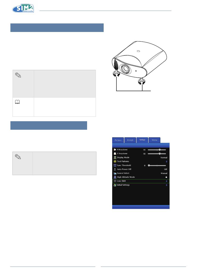
Using the Adjustment Feet
The height of the projector can be adjusted using the
•
adjustment feet when the surface the projector is
placed on is uneven or when the screen is slanted.
The projection of the image can be made higher by
•
adjusting the projector when it is in a location lower
than the screen.
If the screen is at an angle, the adjustment
•
feet can be
used to adjust the angle of the image.
Adjustment feet
note
When the height of the projector is
•
adjusted, the image may become
distorted (keystoned), depending on
the relative positions of the projector
and the screen. See page 24 for
details on keystone correction.
info
When lowering the projector, be
•
careful
not to get your finger caught
in the area between the adjustment
foot and the projector.
Using the lens shift
The height and width of the projected image can be
adjusted to be within the shift range of the lens by
motorized control at the lens shift on main menu.
note
In Setup menu, select Lens Shift
•
Function.
When moving the lens, if the projected
•
image remains still, turn the remote
key in reverse direction.
English
MiCO 50
13
setting up the screen
Position the projector perpendicular to the screen with all feet flat and level to achieve an optimal image.
note
The projector lens should be centered in the middle of the screen. If the horizontal line passing
•
through the lens center is not perpendicular to the screen, the image will be distorted, making
viewing difficult.
For an optimal image, position the screen so that it is not in direct sunlight or room light. Light
•
falling directly on the screen washes out the colors, making viewing difficult. Close the
curtains and dim the lights when setting up the screen in a sunny or bright room.
A polarizing screen cannot be used with this projector.
•
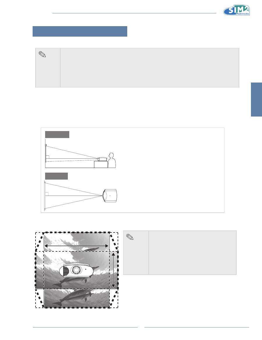
standard setup (Front Projection)
Place the projector at the required distance from the screen according to
n
the desired picture size. (See page 14)
An Example of standard setup
90
Audience
90
side View
Top View
The distance from the screen to the projector may
•
vary depending on the size of the screen.
The default setting can be used, when placing the
•
projector in front of the screen. If the projected image
is reversed or inverted, readjust the setting to “Floor”
for “Orientation” in the “Image” menu.
Place the projector so that an imaginary horizontal
•
line that passes through the center of the lens is
perpendicular to the screen.
note
2D Lens Shift Ability:
Range: UP 60%, Down 25%,
•
Left 7.5%, Right 7.5%.
It is recommended that images be
•
projected onto the dashed line octagonal
area for fine image quality.
There is a tolerance of ±2.5% in the
•
formula above.
H
H
V
V
MiCO 50
14
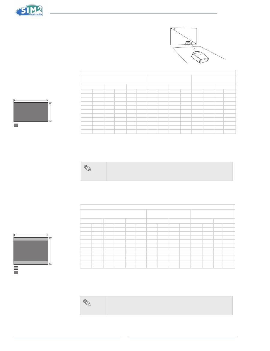
Screen Size and Projection Distance (Short
throw lens)
When using a wide screen
(16:9)
In case of displaying the 16:9
picture on the whole area of the
16:9 screen.
9
16
: Picture area
When using a normal screen
(4:3)
In case of setting the 16:9 picture
to the full horizontal width of the
4:3 screen.
3
4
: Screen area
: Picture area
Wide Screen 16:9
Screen Size
Throw Distance
Center of lens to edge of
image bottom
Diagonal size
Width
Height
Maximum
Minimum
Up
down
in
cm
in
cm
in
cm
ft
m
ft
m
in
cm
in
cm
300.0
762.0
261.5
664.1
147.1 373.6
45.1
13.7
32.2
9.8
14.7
37.4 -110.3 -280.2
250.0
635.0
217.9
553.5
122.6 311.3
37.6
11.4
26.8
8.2
12.3
31.1
-91.9 -233.5
200.0
508.0
174.3
442.8
98.1
249.1
30.0
9.2
21.4
6.5
9.8
24.9
-73.5 -186.8
150.0
381.0
130.7
332.1
73.5
186.8
22.5
6.9
16.1
4.9
7.4
18.7
-55.2 -140.1
133.0
337.8
115.9
294.4
65.2
165.6
20.0
6.1
14.3
4.3
6.5
16.6
-48.9 -124.2
106.0
269.2
92.4
234.7
52.0
132.0
15.9
4.9
11.4
3.5
5.2
13.2
-39.0
-99.0
100.0
254.0
87.2
221.4
49.0
124.5
15.0
4.6
10.7
3.3
4.9
12.5
-36.8
-93.4
92.0
233.7
80.2
203.7
45.1
114.6
13.8
4.2
9.9
3.0
4.5
11.5
-33.8
-85.9
84.0
213.4
73.2
186.0
41.2
104.6
12.6
3.8
9.0
2.7
4.1
10.5
-30.9
-78.5
72.0
182.9
62.8
159.4
35.3
89.7
10.8
3.3
7.7
2.4
3.5
9.0
-26.5
-67.2
The formula for screen size and projection distance
Y1 (Max.) = 0.15x
Y2 (Min.) = 0.107x
Z1 (Upper) = 0.049x
Z2 (Lower) = -0.367x
x : Screen size (in)
y : Projection distance (ft)
z : Distance from the lens center to the lower
edge of the image (in)
note
There is a tolerance of ±3% in the formula above.
•
Values with a minus (-) sign indicate the lens center is above
•
the bottom of the image.
Standard Screen 4:3
Screen Size
Throw Distance
Center of lens to edge of
image bottom
Diagonal size
Width
Height
Maximum
Minimum
Up
down
in
cm
in
cm
in
cm
ft
m
ft
m
in
cm
in
cm
300.0
762.0
240.0
609.6
180.0 457.2
41.4
12.6
29.5
9.0
18.0
45.7 -135.0 -342.9
250.0
635.0
200.0
508.0
150.0 381.0
34.5
10.5
24.6
7.5
15.0
38.1 -112.5 -285.8
200.0
508.0
160.0
406.4
120.0 304.8
27.6
8.4
19.7
6.0
12.0
30.5
-90.0 -228.6
150.0
381.0
120.0
304.8
90.0
228.6
20.7
6.3
14.8
4.5
9.0
22.9
-67.5 -171.5
133.0
337.8
106.4
270.3
79.8
202.7
18.3
5.6
13.1
4.0
8.0
20.3
-59.9 -152.0
106.0
269.2
84.8
215.4
63.6
161.5
14.6
4.5
10.4
3.2
6.4
16.2
-47.7 -121.2
100.0
254.0
80.0
203.2
60.0
152.4
13.8
4.2
9.8
3.0
6.0
15.2
-45.0 -114.3
92.0
233.7
73.6
186.9
55.2
140.2
12.7
3.9
9.0
2.8
5.5
14.0
-41.4 -105.2
84.0
213.4
67.2
170.7
50.4
128.0
11.6
3.5
8.3
2.5
5.0
12.8
-37.8
-96.0
72.0
182.9
57.6
146.3
43.2
109.7
9.9
3.0
7.1
2.2
4.3
11.0
-32.4
-82.3
The formula for screen size and projection distance
Y1 (Max.) = 0.138x
Y2 (Min.) = 0.098x
Z1 (Upper) = 0.06x
Z2 (Lower) = -0.45x
x : Screen size (in)
y : Projection distance (ft)
z : Distance from the lens center to the
lower edge of the image (in)
note
There is a tolerance of ±3% in the formula above.
•
Values with a minus (-) sign indicate the lens center is above
•
the bottom of the image.
English
MiCO 50
15
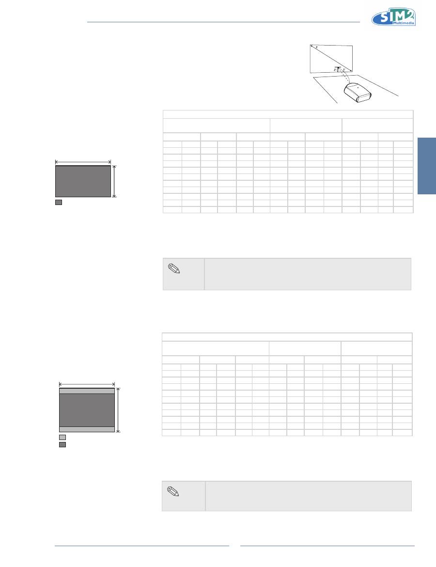
Screen Size and Projection Distance (Long
throw lens)
When using a wide screen
(16:9)
In case of displaying the 16:9
picture on the whole area of the
16:9 screen.
9
16
: Picture area
When using a normal screen
(4:3)
In case of setting the 16:9 picture
to the full horizontal width of the
4:3 screen.
3
4
: Screen area
: Picture area
Wide Screen 16:9
Screen Size
Throw Distance
Center of lens to edge of
image bottom
Diagonal size
WIdth
Height
Maximum
Minimum
Up
down
in
cm
in
cm
in
cm
ft
m
ft
m
in
cm
in
cm
300.0
762.0
261.5
664.1
147.1 373.6
89.4
27.2
45.3
13.8
14.7
37.4 -110.3 -280.2
250.0
635.0
217.9
553.5
122.6 311.3
74.5
22.7
37.7
11.5
12.3
31.1
-91.9 -233.5
200.0
508.0
174.3
442.8
98.1
249.1
59.6
18.2
30.2
9.2
9.8
24.9
-73.5 -186.8
150.0
381.0
130.7
332.1
73.5
186.8
44.7
13.6
22.6
6.9
7.4
18.7
-55.2 -140.1
133.0
337.8
115.9
294.4
65.2
165.6
39.6
12.1
20.1
6.1
6.5
16.6
-48.9 -124.2
106.0
269.2
92.4
234.7
52.0
132.0
31.6
9.6
16.0
4.9
5.2
13.2
-39.0
-99.0
100.0
254.0
87.2
221.4
49.0
124.5
29.8
9.1
15.1
4.6
4.9
12.5
-36.8
-93.4
92.0
233.7
80.2
203.7
45.1
114.6
27.4
8.4
13.9
4.2
4.5
11.5
-33.8
-85.9
84.0
213.4
73.2
186.0
41.2
104.6
25.0
7.6
12.7
3.9
4.1
10.5
-30.9
-78.5
72.0
182.9
62.8
159.4
35.3
89.7
21.5
6.5
10.9
3.3
3.5
9.0
-26.5
-67.2
The formula for screen size and projection distance
Y1 (Max.) = 0.298x
Y2 (Min.) = 0.151x
Z1 (Upper) = 0.049x
Z2 (Lower) = -0.367x
x : Screen size (in)
y : Projection distance (ft)
z : Distance from the lens center to the lower
edge of the image (in)
note
There is a tolerance of ±3% in the formula above.
•
Values with a minus (-) sign indicate the lens center is above
•
the bottom of the image.
Standard Screen 4:3
Screen Size
Throw Distance
Center of lens to edge of
image bottom
Diagonal size
WIdth
Height
Maximum
Minimum
Up
down
in
cm
in
cm
in
cm
ft
m
ft
m
in
cm
in
cm
300.0
762.0
240.0
609.6
180.0 457.2
82.1
25.0
41.5
12.7
18.0
45.7 -135.0 -342.9
250.0
635.0
200.0
508.0
150.0 381.0
68.4
20.8
34.6
10.6
15.0
38.1 -112.5 -285.8
200.0
508.0
160.0
406.4
120.0 304.8
54.7
16.7
27.7
8.4
12.0
30.5
-90.0 -228.6
150.0
381.0
120.0
304.8
90.0
228.6
41.0
12.5
20.8
6.3
9.0
22.9
-67.5 -171.5
133.0
337.8
106.4
270.3
79.8
202.7
36.4
11.1
18.4
5.6
8.0
20.3
-59.9 -152.0
106.0
269.2
84.8
215.4
63.6
161.5
29.0
8.8
14.7
4.5
6.4
16.2
-47.7 -121.2
100.0
254.0
80.0
203.2
60.0
152.4
27.4
8.3
13.8
4.2
6.0
15.2
-45.0 -114.3
92.0
233.7
73.6
186.9
55.2
140.2
25.2
7.7
12.7
3.9
5.5
14.0
-41.4 -105.2
84.0
213.4
67.2
170.7
50.4
128.0
23.0
7.0
11.6
3.5
5.0
12.8
-37.8
-96.0
72.0
182.9
57.6
146.3
43.2
109.7
19.7
6.0
10.0
3.0
4.3
11.0
-32.4
-82.3
The formula for screen size and projection distance
Y1 (Max.) = 0.273x
Y2 (Min.) = 0.138x
Z1 (Upper) = 0.06x
Z2 (Lower) = -0.45x
x : Screen size (in)
y : Projection distance (ft)
z : Distance from the lens center to the lower
edge of the image (in)
note
There is a tolerance of ±3% in the formula above.
•
Values with a minus (-) sign indicate the lens center is above
•
the bottom of the image.
MiCO 50
16
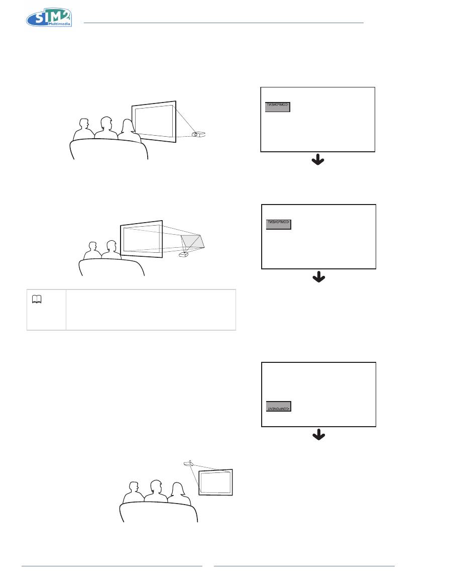
Projection from behind the screen
Projecting a Reversed/inverted image
Place a translucent screen between the projector and the audience.
n
Reverse the image by setting “Floor Rear” for “Orientation” in the
n
“Image” menu.
Projection using a mirror
Place a mirror (normal flat type) in front of the lens.
n
Reverse the image by setting “Floor Rear” for “Orientation” in the
n
“Image” menu, when the mirror is placed on the side where the
audience is.
info
When using a mirror, be sure to carefully position
•
both the projector and the mirror so that the light
does not shine into the eyes of the audience.
Ceiling-mount setup
It is recommended that you use the optional ceiling-mount bracket
n
for this installation.
Before mounting the projector, contact your nearest Authorized
n
Service Center or Dealer to obtain the recommended ceiling-
mount bracket (sold separately).
Be sure to adjust the position of the projector to match the
n
distance (Z) from the lens center position to the lower edge of the
image, when mounting the projector on the ceiling.
Invert the image by setting “Ceiling” for “Orientation” in the “Image”
n
menu.
When using the default setting.
q
On-screen Display
The image is reversed.
When using the default setting.
q
On-screen Display
The image is reversed.
When using the default setting.
q
On-screen Display
The image is reversed.
English
MiCO 50
17
Basic Operation 3.
image Projection
Basic Procedure
Connect the required external equipment to the projector
before operating the following procedures.
info
The language preset at the factory is
•
English.
If you want to change the on-screen display
to another language, reset the language
according to the procedure on page 18.
Plug the power cord into the wall outlet. Press
1
the power switch to turn on the projector.
Press 0 on the remote control or
2
on the
keypad of the projector.
The power indicator illuminates blue, and the projector
•
enters power on mode.
note
The power indicator illuminates,
•
indicating the status of the LED.
Red:
The power is ready.
Blue:
The image is displayed
Press 0 on the remote control to turn on the
•
“Source” selection menu when in normal
operation.
Press the source button on the projector to select
3
the inPUT mode.
KEY 1
Selects the source Composite.
KEY 2
Selects the source S-Video.
KEY 3
Selects the source Component.
KEY 4
Selects the source Graphics RGB.
KEY 5
Selects the source HDMI 1.
KEY 6
Selects the source HDMI 2.
KEY 7
Selects the source SCART
note
When a signal is not received,
•
“NO SIGNAL” will be displayed.
Set SCART enabled before
•
selecting the SCART input.
Press
4
on the remote control or on the projector to turn off the projector.
ESC
SOURCE
MENU
p
,
q
,
t
,
u
buttons
Power
MEnU
EsC
source
Remote control sensor
Red lED
Blue lED
LIGHT
F1
ZOOM
FOCUS
F2
EsC button
MEnU +/- button
Power button
ESC
SOURCE
MENU
p
,
q
,
t
,
u
buttons
Keys 1-7
selects the sources
directly.
1 Composite
2 s-ViDEO
3 COMPOnEnT
4 gRAPhiCs RgB
5 hDMi 1
6 hDMi 2
7 sCART
source button
MiCO 50
18
On-screen Display language
The on-screen display language of the projector can be set to
English, Italiano, Français, Deutsch, Español, Português, Русский
,
简体中文
.
Press “MEnU +” on remote control then select the
1
menu “Menu”.
The menu will be displayed.
•
Press
2
u
to select “language”.
Press
3
p
or
q
to select desired language, and then
press
u
.
The desired language will be set as the on-screen display.
•
Press “EsC”.
4
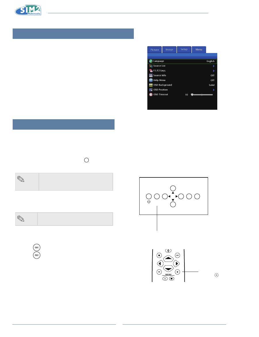
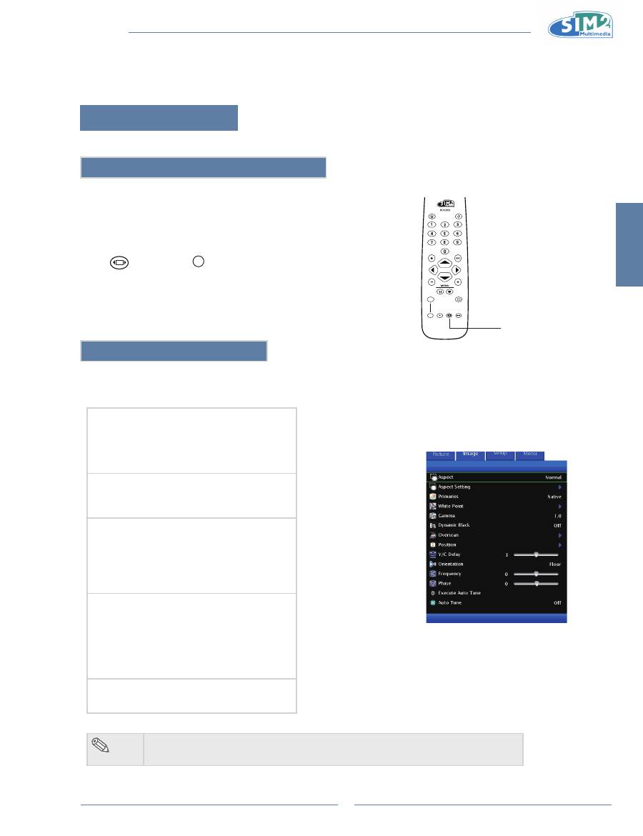
Using the Menu screen
This projector has one set of menu screens that allow you to adjust the image and various projector
settings. You can operate the menus from the projector or remote control as follows:
Menu Selections (Adjustments)
Press “MEnU +” on remote or
1
MENU
on keypad.
The menu screen is displayed.
•
note
When no input source displays,
•
the"Picture" and "Image" menu can
not be selected.
Press “MEnU +” to select the desired menu.
2
Press
3
p
or
q
to select the desired item.
note
The selected item will be highlighted.
•
Press
4
t
or
u
to adjust the item selected.
The adjustment is stored.
•
Press
5
to return to “Main MEnU”.
Press
6
, the menu screen will disappear.
ESC
SOURCE
MENU
MEnU button
LIGHT
F1
ZOOM
FOCUS
F2
MEnU +
button
English
MiCO 50
19
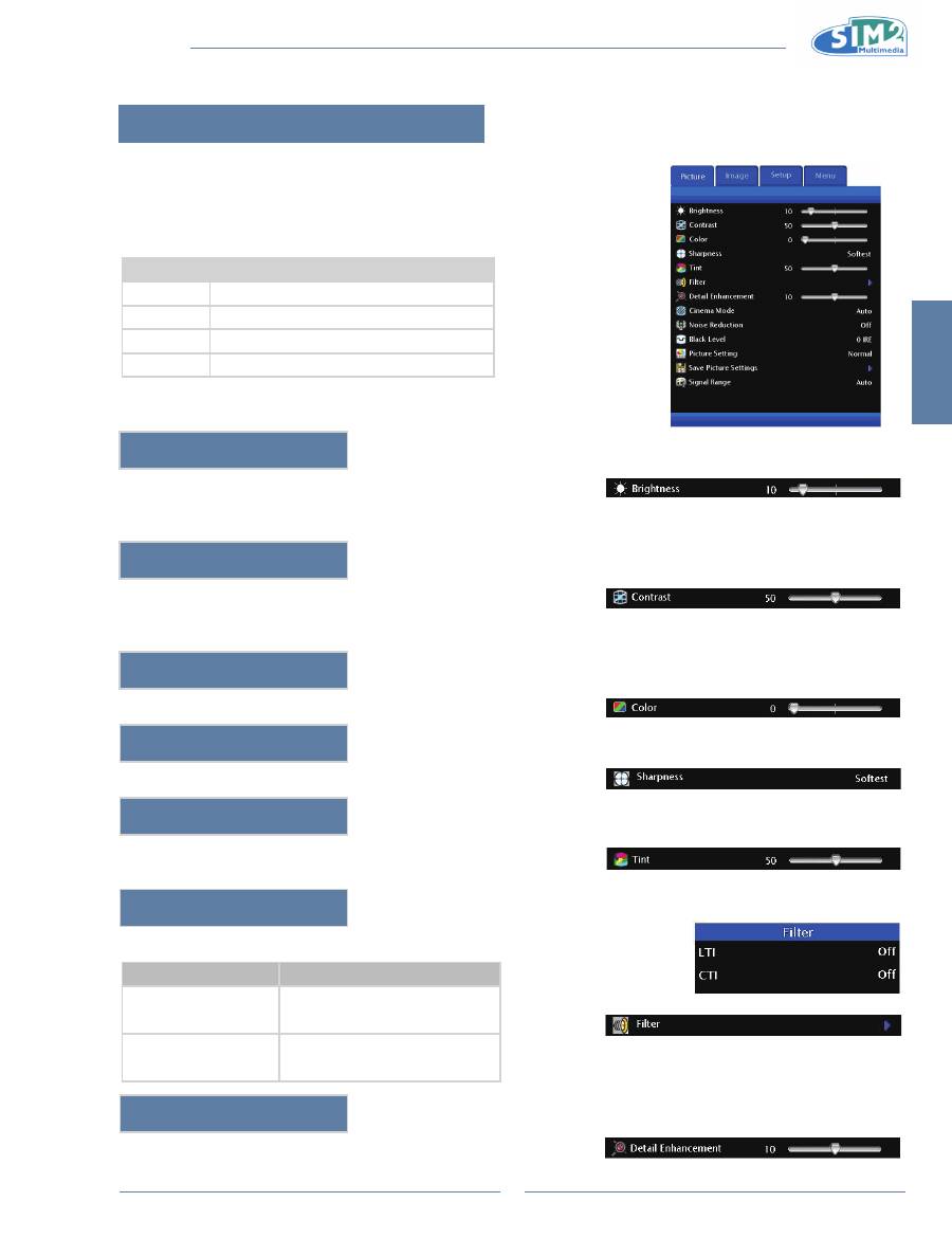
Adjusting the Picture
You can adjust the projector's picture to your preferences
with the following picture settings.
Adjusting Image Preferences
item
Description
Brightness
Adjusts the brightness of an image.
Contrast
Adjusts the contrast level.
Color
Adjusts the color intensity of an image.
Tint
Adjusts the tones of an image.
Brightness
Use this option to adjust the overall brightness of the image. Use this
control in conjunction with contrast to fine-tune the display. The scale is
from 0 to 100.
Contrast
Use this option to adjust the contrast of the image. Use this control in
conjunction with brightness to fine-tune the display. The scale is from 0 to
100.
Color
Use this option to adjust the color intensity of the image.
sharpness
Use this option to adjust the clarity and focus of the image.
Tint
Use this option to adjust the tint of your image. Press
u
to make the
image more green. Press
t
to make the image more purple.
Filter
This function allows you to set the LTI and CTI level.
Selection
Description
LTI
(Luminance Transient
Improvement)
Adjusts the LTI level to enhance
luminance, filter fuzzy edges and
remove smear.
CTI
(Colour Transient
Improvement)
Adjusts the CTI level to enhance
colour, filter fuzzy edges, and
remove smear.
Detail Enhancement
This function sharpens the details of the picture.
MiCO 50
20
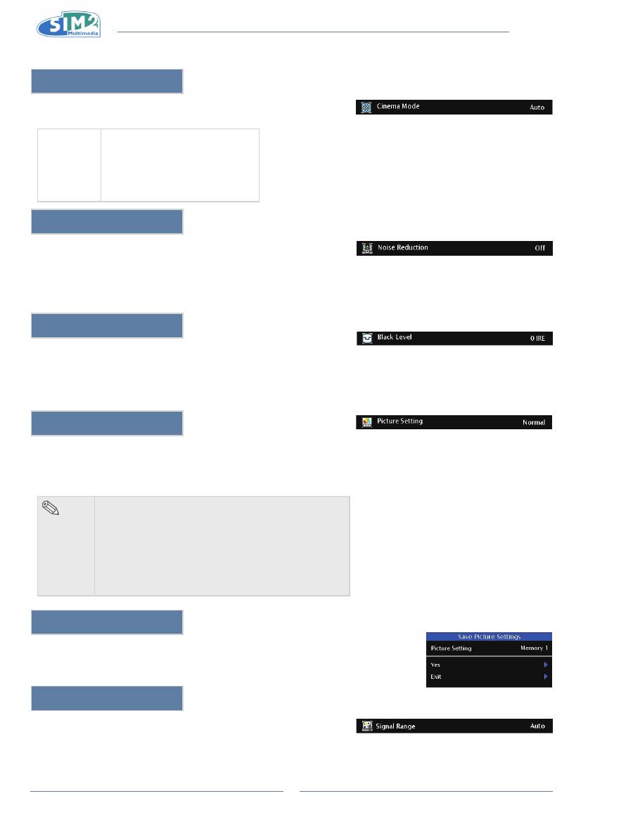
Cinema Mode
This function allows you to determine the type of incoming video content-
film. Different algorithms are applied for each of the content types.
Cinema
Mode
Reproduces the image of the film
source clearly. Displays the
optimized image of film transformed
with 3:2 pull down (NTSC and
PAL60Hz) or 2:2 pull down (PAL
50Hz and SECAM) enhancement to
progressive mode images.
noise Reduction
This function is only available for SDTV (480i/576i) and EDTV
(480p/576p) signals.
Noise Reduction is useful for clearing up noisy images. Turn it Low,
Medium, or High to keep in mind that reducing noise (which reduces high
frequencies) may also “soften” the image.
Black level
This function is only available for S-Video and Composite. This control
compensates for incoming elevated black levels present in certain video
signals. For some types of video, you may want to override the setting.
Set it to 7.5 IRE if blacks appear elevated (dark gray). If blacks appear
“crushed” (too dark), set it to 0 IRE.
Picture setting
This function stores Brightness, Contrast, Color, Sharpness, Tint, Filter,
Detail Enhancement, Gamma, Primaries, White Point, Overscan, Aspect
Ratio, Noise Reduction, and Black Level settings. Each stored setting is
reassigned to each input.
note
When Recalling saved Contents:
•
When selecting a saved memory number, the contents
of the “Picture” menu change to the adjustment values
of the saved memory number.
When Editing saved Contents:
•
Edit the contents of the “Picture” menu after selecting
the Memory number for which adjustment values are
to be edited.
save Picture settings
Use this option to save changes you made in “Picture setting” to Memory 1,
Memory 2, or Memory 3.
signal Range
Select signal range 16~235 or 0~255. Only HDMI is available.
English
MiCO 50
21
Easy to Use Functions 4.
image menu
You can adjust the projector's Image to your preferences with the following settings.
selecting the Picture Display Mode
This function allows you to modify or customize the picture display mode
to enhance the input image. Depending on the input signal, you can
choose “Anamorphic”, “Normal”, “LetterBox”, “Panoramic”, “Pixel to
Pixel”, more three user aspects.
Press
on remote or
MENU
on keypad and select Aspect.
Aspect Function
The Aspect function enables you to control how the projector resizes the input image.
The following options are available:
normal
Resolution depends on the Input Signal
•
4:3 input scaled to fit display height
•
Width scaled to maintain 4:3 aspect ratio
•
Black bars on left and right (taking up 25% of the
•
whole display)
Anamorphic
Resolution 1920x1080
•
4:3 input is stretched to fit 16:9 display
•
Stretches entire image.
•
letterBox
Resolution 1920x1080
•
4:3 input scaled to fit display width
•
Height scaled to maintain 4:3 aspect ratio:
•
1440x1080
25% of the entire image on the top and bottom is
•
cropped.
Panoramic
Resolution 1920x1080
•
4:3 input is stretched to fit 16:9 display
•
With 4:3 input, the central ratio remains true to
•
scale, but the image is stretched to fit display
width.
1920x1080 input image is identical to the one
•
displayed in Anamorphic mode.
Pixel to Pixel
Resolution depends on the input signal.
•
Ouput resolution is equal to input resolution.
•
note
The User 1 & 2 are default on Anamorphic and User 3 is default on LetterBox.
•
LIGHT
F1
ZOOM
FOCUS
F2
Aspect Ratio
MiCO 50
22
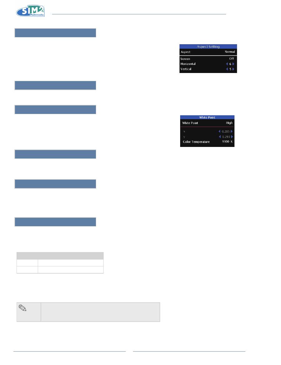
Aspect setting
Choose what Aspect will be to setup and the selected aspect did not apply
1.
on current image except User 1/2/3.
The "Screen" setting is available for every Aspect and used for 12V trigger
2.
setting and its default for each aspect is Off.
The H/V adjustment is only available for Aspect User 1/2/3.
3.
Primaries
The Primaries are the color gamut for RGB. The Primaries is default on Auto.
White Point
The White Point High is closed to 9300K, Medium is to 8500K, Low is to 5400K,
and Native is the LED native white point without any calibration. To adjust
coordinates of white point, select "User".
gamma
Use this option to adjust the gamma correction of the image. Default setting is 2.2. Gamma correction provides eight
sets of gamma corrections 1.0, 1.5, 1.8, 2.0, 2.2, 2.35, 2.5, and 2.8.
Dynamic Black
This function utilizes the contrast of colors to enable black colors to appear blacker on screen while significantly
enhancing the performance of black scenes.
To enable the function, set it to “ON”.
Overscan
This function enables you to remove some edges of the image.
Overscan Type
The following options are available:
Selection
Description
Zoom
Scales or zooms the image.
Crop
Cuts a portion of the image.
Overscan Adjust
This function enables you to adjust the image display on screen. Available options are from 0-10. The
default value is 1 which is suitable for S-Video/Composite, 480i/p, 576i/p, and analog 1080i/p input sources.
Press “
•
t
” or “
u
” to select value.
note
The adjustable range is 0~1 when 1080i and 1035i
•
input.
The adjustable range is 0~5 when 1080p input.
•
