Xoro HSD 8430: BASIC CONNECTIONS
BASIC CONNECTIONS: Xoro HSD 8430
BASIC CONNECTIONS
Connecting to a TV
Ensure that the power switch of this unit and other equipment to be connected is turned off
before commencing connection.
Read through the instructions before connecting other equipment.
Ensure that you observe the colour-coding when connecting audio and video cords.
Please use only one kind of connection with TV set for the unit and choose correct video
output setting, otherwise there may be image distortion.
To get better viewing quality, you are advised using S-video cord to connect the TV set with
S-video input meanwhile changing the TV set to S-video input format.
English
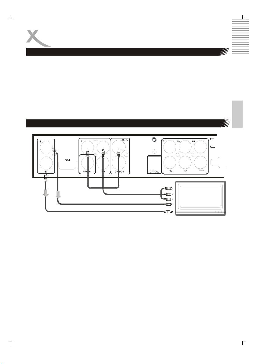
Connecting to a stereo TV set by YUV
DVD player
Component Video Output
TV
Audio Output (left)
Audio Output (right)
The TV set with Y, Cb, Cr input can get more clear picture and realistic image when it con-
nects to Y, Cb, Cr output jacks of this player. The Video out setting must be set as YUV if
you use Y, Cb, Cr output.
Notes:
1. Choose below speaker setting in the Audio menu if you use the TV speaker.
• Front: Large
• Center/Rear/Subwoofer: OFF
At this setting situation which is Stereo effect, the signal from Audio output L, R is
the same as the FL, FR output, also the same as the audio signal from Scart jack.
2. Only one kind of connection to the TV set can be made. If your TV set does not sup-
port Y Pb Pr function, do not switch the VIDEO OUT to Y Pb Pr of the unit, otherwise
there will be no picture output.
11
BASIC CONNECTIONS
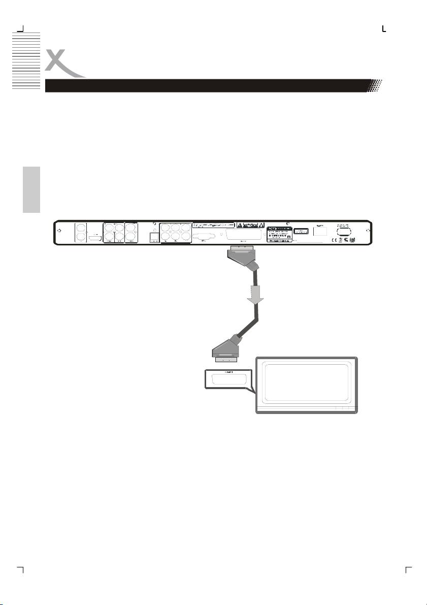
Connection to a TV set with SCART jack
The Scart or Euro AV cable serves as the universal connector for picture, sound and control
signals.
Plug a cable onto the SCART socket at the back of the DVD player and the SCART IN
socket on the rear side of the TV set. Please also refer to your TV sets user manual.
Switch on the TV set and select the Scart input or the respective channel number. For chan-
nel number and input selection please also refer to your TV operating instructions.
Notes :
The Scart interface of this DVD recorder is RGB enable. In RGB mode, the picture quality is
much better than in standard SCART mode. You can activate RGB mode on the video set-
tings page of your DVD recorder, You only can use this mode if it is supported by your TV
set. Otherwise, the use of RGB will result in wrong colour display. please also refer ti your
English
TV set's user manual.
scart out
User can choose the proper video connection according to the TV set jacks and his require-
ment (same as below). Choose below speaker size setting in the setting.
12
BASIC CONNECTIONS
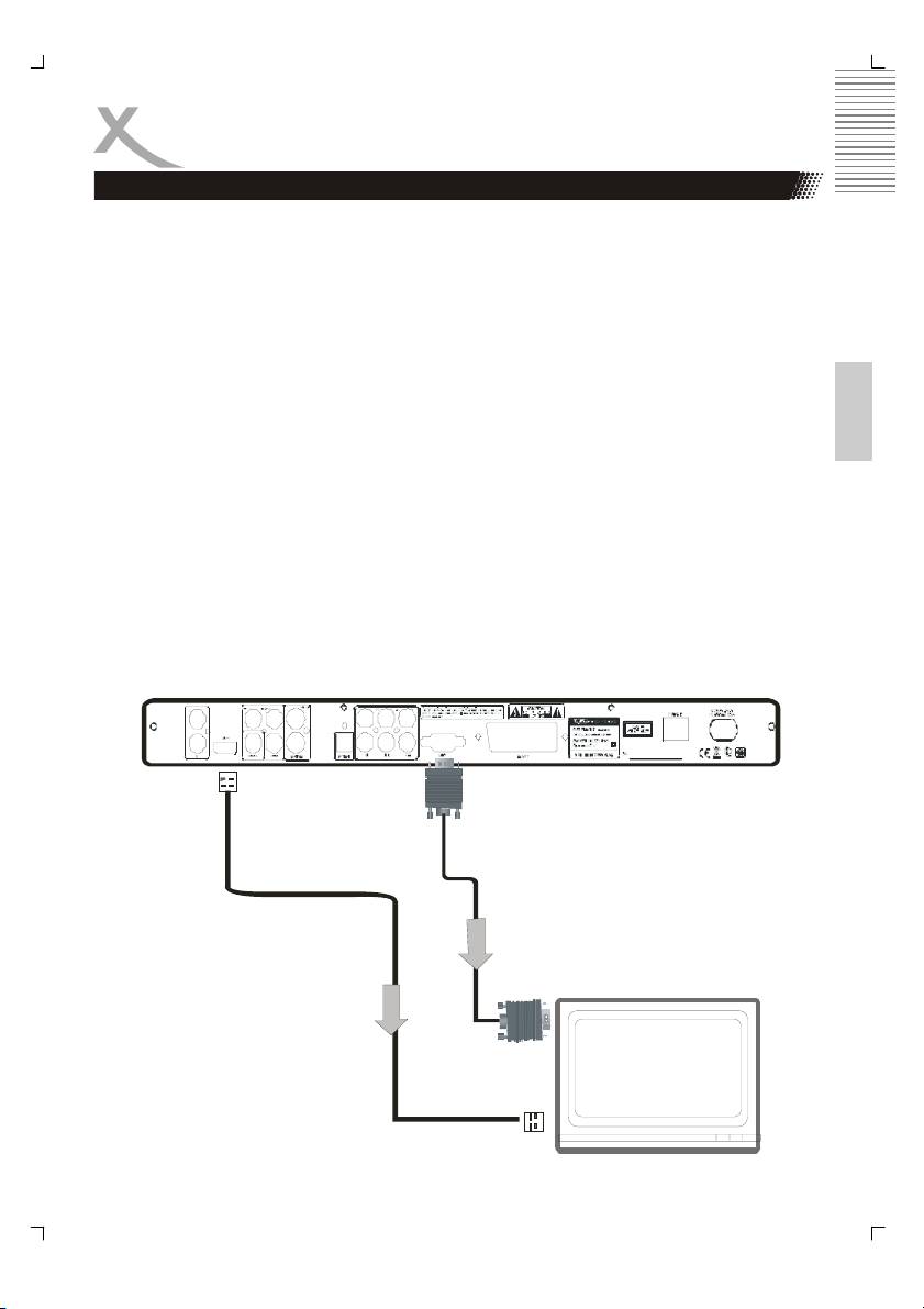
Connecting to a TV set with HDMI or VGA jack
A: Connecting the HDMI jack.
HDMI is a digital transmission technology for both audio and video.
Connect the DVD player and display with a HDMI-HDMI cable. Please note that some TV
set can not support RAW audio. In this case ,please set the DVD player audio digital output
to PCM. Change to video output mode by pressing the V-Mode button on the remote control
until “HD” is displayed on the screen. Change the TV source to HDMI, and than the picture is
available.
If your TV set is not equipped with HDMI, but with DVI input, you can use a conversion cable
English
or an adapter to DVI. As DVI does not transmit sound, you also must add an audio connec-
tion
Insert one end of an audio (cinch (RCA)) cable into the white/red cinch (RCA) socket L/R
AUDIO OUT at the back of the DVD player and the other end into the audio input socket
(usualy white/red) on the TV set (usually labelled "AUDIO IN" or "AV IN". Please also refer to
your TV set's user manual)
Switch on the TV set and select the HDMI or DVI input. For input selection please also refer
to your TV operating instructions.
B: Connecting the VGA jack
The VGA output can be used to connect the DVD-Player to the PC monitor.
As VGA does not transmit sound, you also must add an audio connection.
Insert one end of an audio ((Cinch(RCA)) cable into the white /red Cinch (RCA) socket L/R
AUDIO OUT at the back of the DVD player and the other end into the audio input socket
(usually white/red) on the PC monitor or sound system you plan to use.
HDMI OUT
VGA OUT
13
BASIC CONNECTIONS
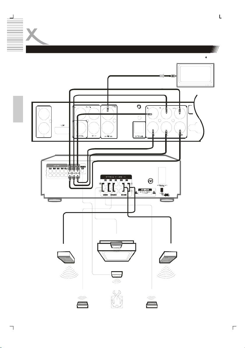
Connection to AV amplifier with 5.1 channel input connector
video out
cent er
rear (left)
front (left)
English
front (right)
rear (right )
av amplifier
subwoofer
center
front (right)front (left)
subwoofer
rear (right)rear (left)
14
BASIC CONNECTIONS
Connection to AV amplifier with 5.1 channel input connector
This player contains a Dolby Digital or MPEG2 decoder. This enables the playback of DVD
recorded in Dolby Digital, MPEG1/2 audio or linear PCM without an external decoder sup-
ports. When the player is connected to an AV amplifier with 5.1 channel input connectors,
theater quality audio could be enjoyed at your home at the time of playing disc recorded in
Dolby digital, MPEG1/2 audio or linear PCM.
Recommendation:
English
Choose following speaker size setting in the setting Audio menu: Front/
Center/Rear
Notes:
1. Choose right audio setting for this player according to your audio system require-
ment after connection is made.
2. If the type of the speaker connected does not satisfy the channels recorded in a
MPEG-2 or Linear PCM disc, the disc will not be played in all channels but only in 2
channels (i.e. even if the front speakers and the center speakers are connected, a
disc recorded in 5.1 channels will be played only in 2 channels)
O
C
p
t
o
i
c
a
a
x
l
i
a
o
l
u
o
t
p
u
u
t
p
t
u
t
15
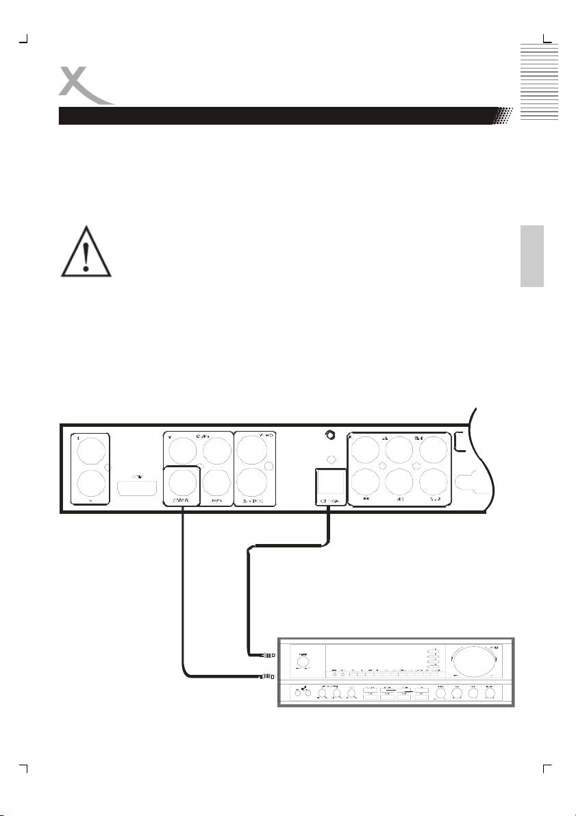
BASIC CONNECTIONS
Connections to an external power amplifier
When DVD discs recorded in DOLBY digital, MPEG audio or other formats are played, cor-
responding bit stream is output from the player OPTICAL and COAXIAL digital audio output
connector. When the player is connected to an external decoder or a power amplifier, you
can enjoy theater-quality at your home.
Notes when connecting the optical digital cable:
Remove the protective cap from the connector, insert the plug-ins of DVD and amplifier
optical slot so that the configurations of both the cable and the connector match. Keep the
protective cap and always reattach the cap when not using the connector to protect against
dust and laser beam.
English
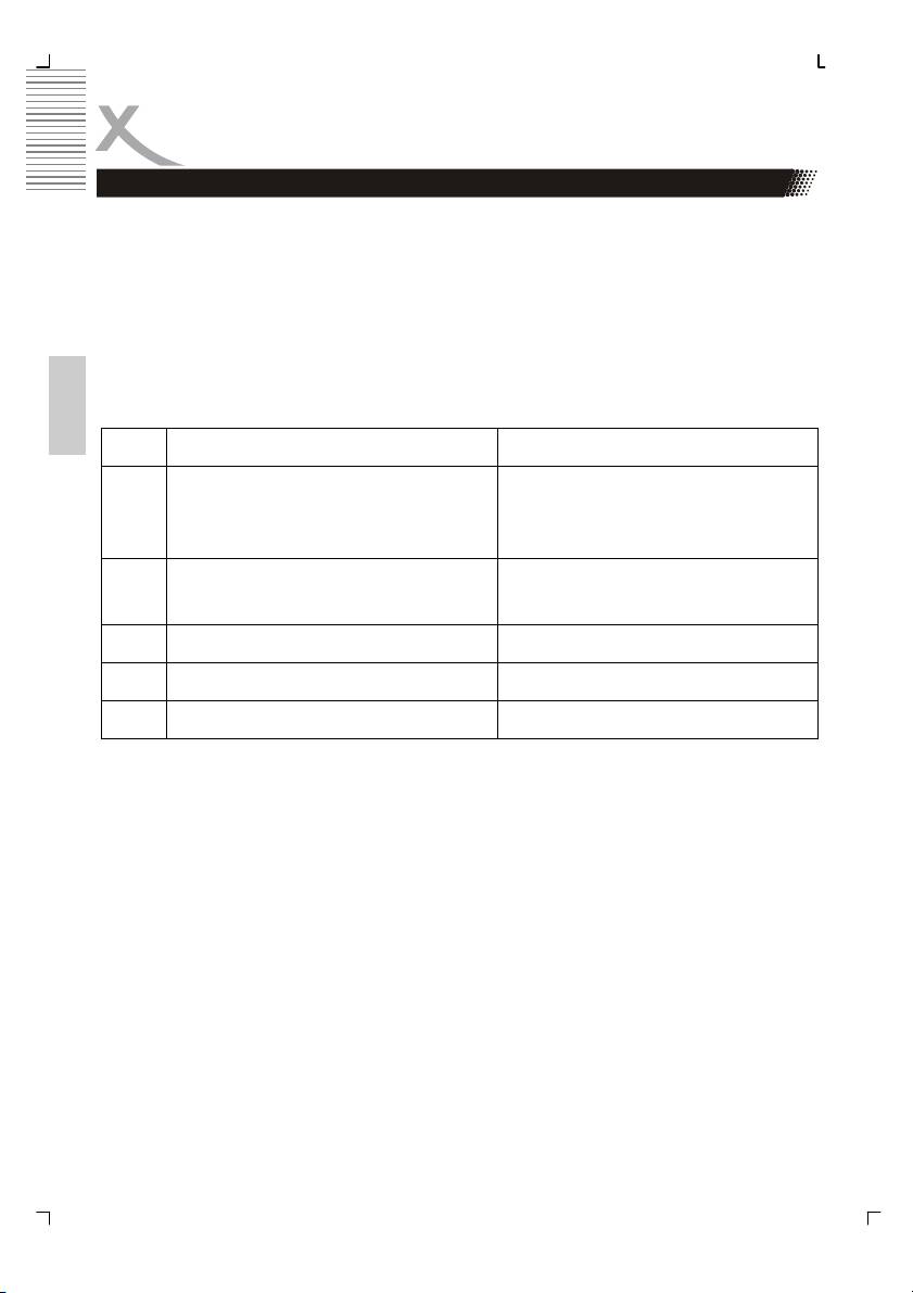
Disc Sound recording format Digital output setting
1
DVD
Dolby Digital
• PCM (44.1 kHz sampling)
• RAW
• OFF
DVD
DTS
• RAW
• OFF
DVD
Linear PCM PCM (44.1 kHz sampling)
DVD
Other PCM (44.1 kHz sampling)
CD
Linear PCM PCM (44.1 kHz sampling)
Concerning the audio output setting for the unit
1
Sound having 96 KHZ sampling is converted to 48 KHZ sampling when it is output from the
coaxial digital audio output connector.
Notes:
Please set the digital output as RAW
Caution for the coaxial/optical digital audio output connector:
Do not connect an amplifier with a Coaxial or optical digital input connector) which does not
contain the Dolby digital or MPEG audio decoder otherwise it may be harmful to your ears
and damage your speakers.
HD resolutions:
This DVD Player reads information (EDID) from the TV to extract data such as type of TV
(HDMI) and resolution, and configures the DVD resolutions accordingly.
16
Оглавление
- HSD 8430 MPEG-4 DVD-Player CD-Ripping Function
- INHALTVERZEICHNIS
- INHALTVERZEICHNIS
- SICHERHEITSHINWEISE
- MERKMALE
- ANSCHLÜSSE & BEDIENELEMENTE
- FERNBEDIENUNG
- BASISANSCHLÜSSE
- BEDIENUNG
- KARTENLESEGERÄT UND USB
- CD-RIPPING
- ANFANGSEINSTELLUNGEN
- HÄUFIGE BEDIENFEHLER
- PROBLEMBEHANDLUNG
- TECHNISCHE DATEN
- GLOSSAR
- CONTENTS
- SAFETY RECAUTIONS
- FEATURES
- REMOTE CONTROL
- BASIC CONNECTIONS
- OPERATION
- OPERATION FOR CARD READER
- CD-RIPPING
- INITIAL SETTINGS
- DISC INFORMATION
- TROUBLESHOOTING
- SPECIFICATIONS
- GLOSSARY
- СОДЕРЖАНИЕ
- МЕРЫ ПРЕДОСТОРОЖНОСТИ
- КРАТКИЙ СЛОВАРЬ ТЕРМИНОВ
- CONTENU
- CARACTÉRISTIQUES
- INTERFACES ET COMMANDES
- TELECOMMANDE
- RACCORDEMENTS DE BASE
- FONCTIONNEMENT
- LECTEUR DE CARTES ET PORT USB
- FONCTION EXTRACTION
- RÉGLAGES INITIAUX
- DÉPANNAGE
- SPÉCIFICATIONS
- GLOSSAIRE
- CONTENIDOS
- CONTENIDOS
- CONSIGNAS DE SEGURIDAD
- CARACTERÍSTICAS
- INTERFACES Y CONTROLES
- MANDO A DISTANCIA
- CONEXIONES BÁSICAS
- OPERACIÓN
- FUNCIONAMIENTO
- FUNCION EXTRACCION
- CONFIGURACIÓN INICIAL
- CONFIGURACIÓN INICIAL
- CONFIGURACIÓN INICIAL
- Solución de problemas
- ESPECIFICACIONES
- GLOSARIO
