Gigabyte 8S661FXME-RZ: Step 3: Installation of Expansion Cards
Step 3: Installation of Expansion Cards: Gigabyte 8S661FXME-RZ
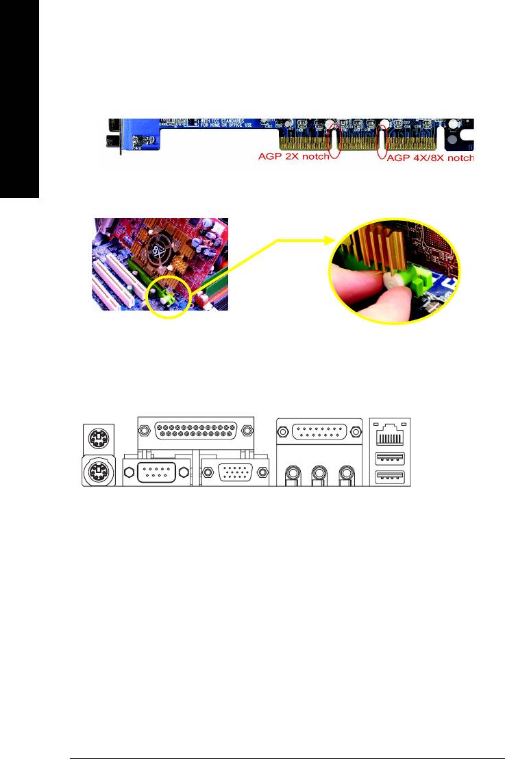
Step 3: Installation of Expansion Cards
1. Read the related expansion card's instruction document before install the expansion card into the computer.
2. Please make sure your AGP card is AGP 4X/8X (1.5V).
English
3. Please carefully pull out the small white-drawable bar at the end of the AGP slot when you try to
install / uninstall the AGP card. Please align the AGP card to the onboard AGP slot and press firmly
down on the slot .Make sure your AGP card is locked by the small white-drawable bar.
AGP Card
Step 4: Installation of I/O Peripherals Cables
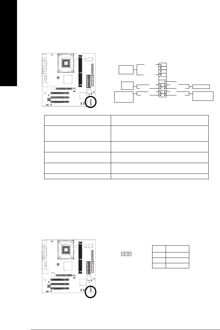
Step 4-1: I/O Back Panel Introduction
Y
\
`
X
Z[
]^
_
a
X PS/2 Keyboard and PS/2 Mouse connector
This connector supports standard PS/2 keyboard and PS/2 mouse.
Y Parallel port (LPT)
Device like printer can be connected to Parallel port.
Z Serial port (COMA)
Mouse and modem etc. can be connected to Serial port.
[ VGA port
Monitor can be connected to VGA port.
\ Game/MIDI port
This connector supports joystick, MIDI keyboard and other relate audio devices.
] Line Out jack
Connect the stereo speakers or earphone to this connector.
^ Line In jack
Devices like CD-ROM, walkman etc. can be connect to Line In jack.
- 12 -8S661FXME-RZ Motherboard
English
_ MIC In jack
Microphone can be connect to MIC In jack.
After installation of the audio driver, you are able to use 2/4/6-channel audio feature by software
selection. You can connect "Front speaker" to "Line Out" jack, Connect "Rear speaker" to "Line In"
jack and connect "Center/Subwoofer" to "MIC In" jack.
` LAN port
LAN is fast Ethernet with 10/100Mbps speed.
a USB port
Before you connect your device(s) into USB connector(s), please make sure your device(s) such
as USB keyboard, mouse, scanner, zip, speaker...etc. Have a standard USB interface. Also make
sure your OS supports USB controller. If your OS does not support USB controller, please contact
OS vendor for possible patch or driver upgrade. For more information please contact your OS or
device(s) vendors.
Step 4-2: Connectors Introduction
13
9
2
6
5
10
4
14
17
18
13
7
12
11
15 16
8
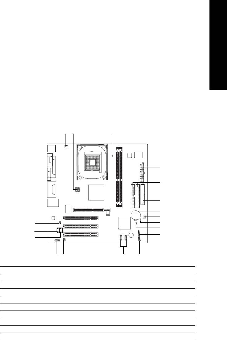
1) ATX_12V
10) BATTERY
2) ATX
11) F_AUDIO
3) CPU_FAN
12) CD_IN
4) SYS_FAN
13) AUX_IN
5) FDD
14) SPDIF_IO
6) IDE1 / IDE2
15) SUR_CEN
7) F_PANEL
16) F_USB1 / F_USB2
8) PWR_LED
17) CLR_CMOS
9) RAM_LED
18) CI
- 13 -
Hardware Installation Process
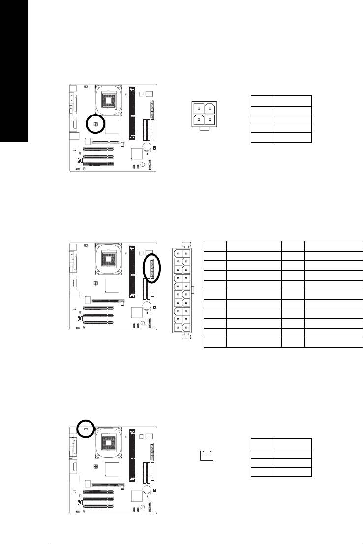
1) ATX_12V (+12V Power Connector)
This connector (ATX _12V) supplies the CPU operation voltage (Vcore).
If this " ATX_ 12V connector" is not connected, system cannot boot.
English
Pin No. Definition
2
1
1 GND
3
2 GND
4
3 +12V
4 +12V
2) ATX (ATX Power)
AC power cord should only be connected to your power supply unit after ATX power cable and other
related devices are firmly connected to the mainboard.
Pin No. Definition
Pin No. Definition
10
20
1 3.3V
11 3.3V
2 3.3V
12 -12V
3 GND
13 GND
4 +5V
14 PS_ON(soft on/off)
5 GND
15 GND
6 +5V
16 GND
7 GND
17 GND
8 Power Good
18 -5V
1
11
9 5V SB (stand by +5V)
19 +5V
10 +12V
20 +5V
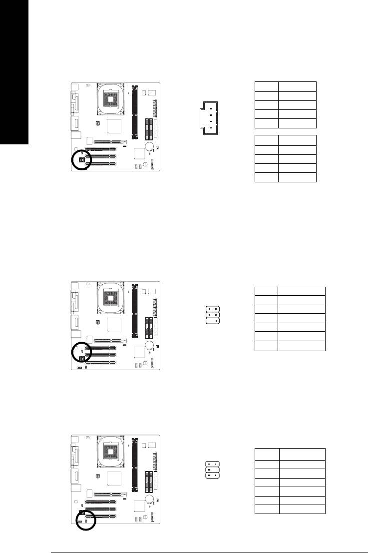
3) CPU_FAN (CPU FAN Connector)
A proper installation of the CPU cooler is essential to prevent the CPU from running under abnormal
condition or damaged by overheating. The CPU fan connector supports Max. current up to 600 mA.
Pin No. Definition
1 GND
1
2 +12V
3 Sense
- 14 -8S661FXME-RZ Motherboard
English
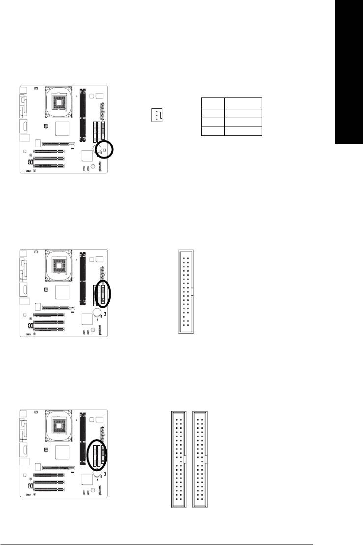
4) SYS_FAN (System Fan Connector)
This connector allows you to link with the cooling fan on the system case to lower the system
temperature.
Pin No. Definition
1 GND
2 +12V
1
3 Sense
5) FDD (Floppy Connector)
Please connect the floppy drive ribbon cables to FDD. It supports 360K,720K,1.2M,1.44M and
2.88Mbytes floppy disk types.
The red stripe of the ribbon cable must be the same side with the Pin1.
34
33
2
1
6) IDE1 / IDE2 (IDE Connector)
Please connect first harddisk to IDE1 and connect CDROM to IDE2.
The red stripe of the ribbon cable must be the same side with the Pin1.
40
39
2
1
IDE1IDE2
- 15 -
Hardware Installation Process
7) F_PANEL (2x10 pins connector)
Please connect the power LED, PC speaker, reset switch and power switch etc. of your chassis
front panel to the F_PANEL connector according to the pin assignment above.
English
1920
SPEAK-
Speaker
Connector
SPEAK+
1
NC
Power
1
PW-
RES+
Switch
Reset Switch
PW+
1
RES-
MSG-
HD-
Message LED/
IDE Hard Disk
MSG+
HD+
Power/
1
1
Active LED
Sleep LED
12
HD (IDE Hard Disk Active LED) Pin 1: LED anode(+)
Pin 2: LED cathode(-)
SPEAK (Speaker Connector) Pin 1: VCC(+)
Pin 2- Pin 3: NC
Pin 4: Data(-)
RES (Reset Switch) Open: Normal Operation
Close: Reset Hardware System
PW (Power Switch) Open: Normal Operation
Close: Power On/Off
MSG (Message LED/Power/ Pin 1: LED anode(+)
Sleep LED) Pin 2: LED cathode(-)
NC NC
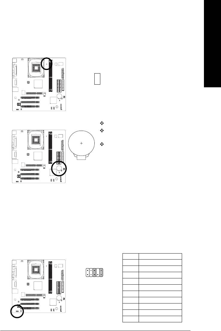
8) PWR_LED
PWR_LED is connect with the system power indicator to indicate whether the system is on/off. It will
blink when the system enters suspend mode. If you use dual color LED, power LED will turn to
another color.
Pin No. Definition
1
1 MPD+
2 MPD-
3 MPD-
- 16 -8S661FXME-RZ Motherboard
English
9) RAM_LED
Do not remove memory modules while RAM_LED is on. It might cause short or other unexpected
damages due to the stand by voltage. Remove memory modules only when AC power cord is
disconnected.
_
+
10) BATTERY
Danger of explosion if battery is incorrectly replaced.
Replace only with the same or equivalent type recom
mended by the manufacturer.
Dispose of used batteries according to the manufacturer's
instructions.
If you want to erase CMOS...
1. Turn off the computer and unplug the power cord.
2. Take out the battery gently and put it aside for about 10
minutes (Or you can use a metal object to connect the
positive and negative pins in the battery holder to make
them short for one minute).
3. Re-install the battery.
4. Plug the power cord and turn on the computer.
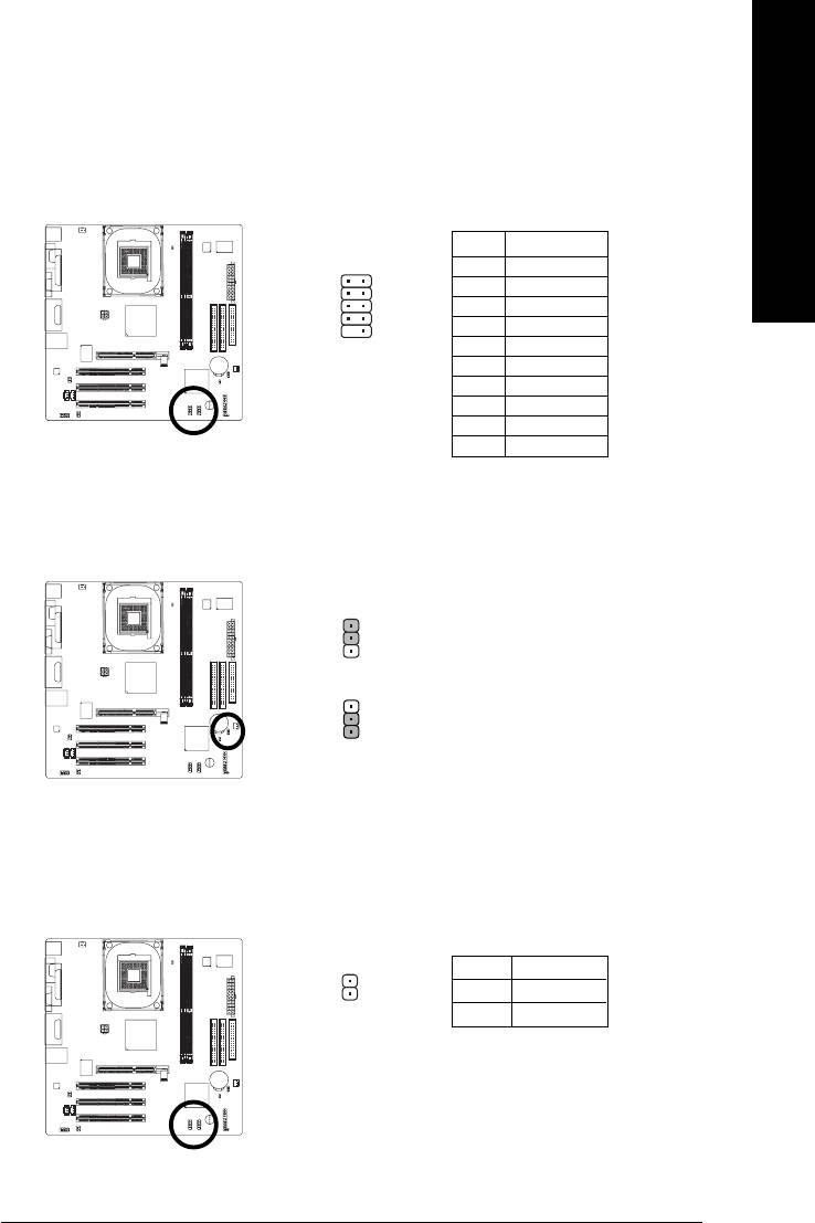
11) F_AUDIO (Front Audio Panel Connector)
If you want to use Front Audio connector, you must remove 5-6, 9-10 Jumper.
In order to utilize the front audio header, your chassis must have front audio connector. Also please
make sure the pin assignments for the cable are the same as the pin assignments for the front audio
header. To find out if the chassis you are buying support front audio connector, please contact your
dealer. Please note, you can have the alternative of using front audio connector or of using rear
audio connector to play sound.
Pin No. Definition
1 MIC
102
2 GND
3 MIC_BIAS
91
4 Power
5 Front Audio(R)
6 Rear Audio(R)/Return R
7NC
8 No Pin
9 Front Audio(L)
10 Rear Audio(L)/Return L
- 17 -
Hardware Installation Process
12/13) CD_IN (CD In Connector, black) / AUX_IN (AUX In Connector, white)
Connect CD-ROM or DVD-ROM audio out to the connector.
Connect other device (such as PCI TV Tunner audio out) to the connector.
Pin No. Definition
English
1
1 CD-L
2 GND
3 GND
4 CD_R
Pin No. Definition
1 AUX-L
2 GND
3 GND
4 AUX_R
14) SPDIF_IO (SPDIF In / Out Connector)
The SPDIF output is capable of providing digital audio to external speakers or compressed AC3
data to an external Dolby Digital Decoder. Use this feature only when your stereo system has
digital input function. Be careful with the polarity of the SPDIF_IO connector. Check the pin
assignment carefully while you connect the SPDIF cable, incorrect connection between the cable
and connector will make the device unable to work or even damage it. For optional SPDIF_IO
cable, please contact your local dealer.
Pin No. Definition
6
5
1 Power
2 No Pin
3 SPDIF
4 SPDIFI
2
1
5 GND
6 GND
15) SUR_CEN
Please contact your nearest dealer for optional SUR_CEN cable.
1
2
Pin No. Definition
1 SUR OUTL
2 SUR OUTR
3 GND
5
6
4 No Pin
5 CENTER_OUT
6 BASS_OUT
- 18 -8S661FXME-RZ Motherboard
English
16) F_ USB1 / F_USB2 (Front USB Connector)
Be careful with the polarity of the front USB connector. Check the pin assignment carefully while
you connect the front USB cable, incorrect connection between the cable and connector will make
the device unable to work or even damage it. For optional front USB cable, please contact your
local dealer.
Pin No. Definition
1
2
1 Power
2 Power
3 USB DX-
4 USB Dy-
5 USB DX+
9
10
6 USB Dy+
7 GND
8 GND
9 No Pin
10 NC
17) CLR_CMOS (Clear CMOS)
You may clear the CMOS data to its default values by this jumper. To clear CMOS, temporarily
short 1-2 pin. Default doesn't include the "Shunter" to prevent from improper use this jumper.
2-3 Short: Normal
1
1-2 Short: Clear CMOS
1
18) CI (Chassis Intrusion, Case Open)
This 2-pin connector allows your system to detect if the chassis cover is removed. You can
check the "Case Opened" status in BIOS Setup.
Pin No. Definition
1 Signal
1
2 GND
- 19 -
Hardware Installation Process

English
- 20 -8S661FXME-RZ Motherboard
Оглавление
- Features Summary
- 8S661FXME-RZ Motherboard Layout
- Block Diagram
- Hardware Installation Process
- Step 2: Installation of Memory
- Step 3: Installation of Expansion Cards
- The Main Menu (For example: BIOS Ver. : F1)
- Standard CMOS Features
- Advanced BIOS Features
- Integrated Peripherals
- Power Management Setup
- PnP/PCI Configurations
- PC Health Status
- MB Intelligent Tweaker(M.I.T.)
- Select Language
- Set Supervisor/User Password
- Save & Exit Setup
- Revision History


