Gigabyte GA-8GEM800: инструкция
Раздел: Компьютерная техника, комплектующие, аксессуары
Тип: Материнская Плата
Инструкция к Материнской Плате Gigabyte GA-8GEM800
GA-8GEM800
®
®
Intel
Pentium
4 Socket 478 Processor Motherboard
User's Manual
Rev. 1001
12ME-8GEM800-1001
Sept. 1, 2004
GA-8GEM800
Motherboard
Sept. 1, 2004
GA-8GEM800
Motherboard

Copyright
© 2004 GIGA-BYTE TECHNOLOGY CO., LTD. All rights reserved.
The trademarks mentioned in the manual are legally registered to their respective companies.
Notice
The written content provided with this product is the property of Gigabyte.
No part of this manual may be reproduced, copied, translated, or transmitted in any form or by any
means without Gigabyte's prior written permission. Specifications and features are subject to
change without prior notice.
Product Manual Classification
In order to assist in the use of this product, Gigabyte has categorized the user manual in the
following:
n For quick installation, please refer to the "Hardware Installation Guide" included with the
product.
n For detailed product information and specifications, please carefully read the
"Product User Manual".
n For detailed information related to Gigabyte's unique features, please go to Gigabyte's
website under "Technology Guide" where information can be downloaded in .pdf format.
Fore more product details, please click onto Gigabyte's website at www.gigabyte.com.tw

Table of Contents
GA-8GEM800 Motherboard Layout.............................................................................6
Block Diagram ...........................................................................................................7
Chapter 1 Hardware Installation..................................................................................9
1-1 Considerations Prior to Installation .........................................................................9
1-2 Feature Summary .................................................................................................10
1-3 Installation of the CPU and Heatsink...................................................................12
1-3-1 Installation of the CPU ....................................................................................12
1-3-2 Installation of the Heatsink ..............................................................................13
1-4 Installation of Memory...........................................................................................14
1-5 Installation of Expansion Cards ...........................................................................16
1-6 I/O Back Panel Introduction .................................................................................17
1-7 Connectors Introduction ........................................................................................18
Chapter 2 BIOS Setup ............................................................................................29
The Main Menu (For example: BIOS Ver. : E2)............................................................30
2-1 Standard CMOS Features ...................................................................................32
2-2 Advanced BIOS Features....................................................................................34
2-3 Integrated Peripherals ...........................................................................................36
2-4 Power Management Setup ...................................................................................39
2-5 PnP/PCI Configurations.......................................................................................41
2-6 PC Health Status ..................................................................................................42
2-7 Frequency/Voltage Control ...................................................................................43
2-8 Top Performance....................................................................................................44
2-9 Load Fail-Safe Defaults .........................................................................................45
2-10 Load Optimized Defaults .......................................................................................45
2-11 Set Supervisor/User Password ..........................................................................46
2-12 Save & Exit Setup ...............................................................................................47
2-13 Exit Without Saving ..............................................................................................47
Chapter 3 Drivers Installation ...................................................................................49
3-1 Install Chipset Drivers ..........................................................................................49
3-2 Software Applications ............................................................................................50
3-3 Driver CD Information...........................................................................................50
3-4 Hardware Information ...........................................................................................51
3-5 Contact Us ............................................................................................................51
- 4 -

Chapter 4 Appendix ...............................................................................................53
4-1 Unique Software Utility.........................................................................................53
4-1-1 Xpress Recovery Introduction .......................................................................53
4-1-2 BIOS Flash Method Introduction ....................................................................56
4-1-3 2 / 4 / 6 Channel Audio Function Introduction...............................................65
4-2 Troubleshooting ......................................................................................................71
- 5 -
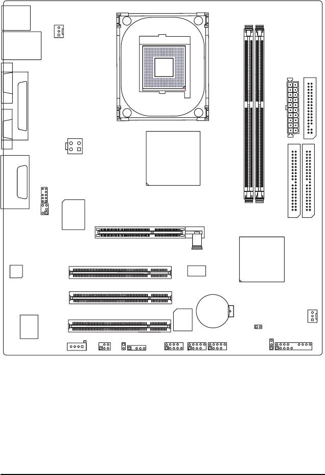
GA-8GEM800 Motherboard Layout
KB_MS
CPU_FAN
USB
LAN
ATX
FDD
COMA
SOCKET478
LPT
VGA
GA-8GEM800
ATX_12V
Intel 845GE
LINE_OUTMIC_IN
F_AUDIO
GAME
LINE_IN
IT8712
DDR1
DDR2
SUR_CEN
AGP
IDE2 IDE1
CODEC
PCI1
ICH4
PCI2
BAT
PCI3
RTL
BIOS
CLR_CMOS
SYS _FAN
8100C
PWR_LED
CD_IN
SPDIF_IO
CI
COMB
F_USB1
F_USB2
F_PANEL
IR
55
- 6 -
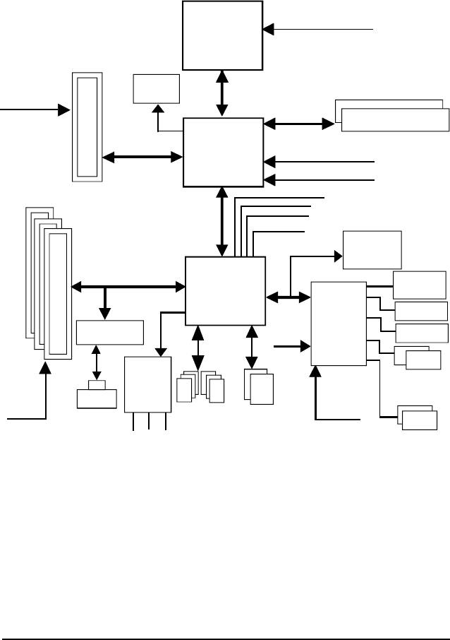
Block Diagram
Pentium 4
CPUCLK+/- (100/133MHz)
Socket 478
CPU
AGP 4X
AGPCLK
System Bus
VGA Port
(66MHz)
400/533MHz
DDR
200/266/333MHz
Intel 82845GE
66MHz
HCLK+/- (100/133MHz)
66MHz
3 PCI
33 MHz
14.318 MHz
48 MHz
BIOS
Intel ICH4
Game Port
LPC BUS
Floppy
IT8712
RTL8100C
24 MHz
LPT Port
AC97 Link
AC97
PS/2
PCICLK
CODEC
KB/Mouse
RJ45
(33MHz)
6 USB
ATA33/66/100
33 MHz
Ports
IDE Channels
COM
(2.0/1.1)
MIC
Ports
LINE-IN
LINE-OUT
- 7 -

- 8 -

English
Chapter 1 Hardware Installation
1-1 Considerations Prior to Installation
Preparing Your Computer
The motherboard contains numerous delicate electronic circuits and components which can
become damaged as a result of electrostatic discharge (ESD). Thus, prior to installation, please
follow the instructions below:
1. Please turn off the computer and unplug its power cord.
2. When handling the motherboard, avoid touching any metal leads or connectors.
3. It is best to wear an electrostatic discharge (ESD) cuff when handling electronic components
(CPU, RAM).
4. Prior to installing the electronic components, please have these items on top of an antistatic pad or
within a electrostatic shielding container.
5. Please verify that you the power supply is switched off before unplugging the power supply connector
from the motherboard.
Installation Notices
1. Prior to installation, please do not remove the stickers on the motherboard. These stickers are required
for warranty validation.
2. Prior to the installation of the motherboard or any hardware, please first carefully read theinformation
in the provided manual.
3. Before using the product, please verify that all cables and power connectors are connected.
4. To prevent damage to the motherboard, please do not allow screws to come in contact with the
motherboard circuit or its components.
5. Please make sure there are no leftover screws or metal components placed on the motherboard or
within the computer casing.
6. Please do not place the computer system on an uneven surface.
7. Turning on the computer power during the installation process can lead to damage to system
components as well as physical harm to the user.
8. If you are uncertain about any installation steps or have a problem related to the use of the product,
please consult a certified computer technician.
Instances of Non-Warranty
1. Damage due to natural disaster, accident or human cause.
2. Damage as a result of violating the conditions recommended in the user manual.
3. Damage due to improper installation.
4. Damage due to use of uncertified components.
5. Damage due to use exceeding the permitted parameters.
6. Product determined to be an unofficial Gigabyte product.
Hardware Installation- 9 -

1-2 Feature Summary
®
®
CPU Socket 478 for Intel
Pentium
4 (Northwood, Prescott) processor with
HT Technology
English
Supports 400/533MHz FSB
L2 cache varies with processors
®
Chipset Northbridge:Intel
845GE
®
Southbridge: Intel
ICH4
Memory 2 184-pin DDR DIMM sockets
(note 1)
Supports DDR333/DDR266/DDR200 DIMM
Supports up to 2GB DRAM (Max.)
Supports only 2.5V DDR DIMM
Slots 1 AGP slot 4X (1.5V) device support
3 PCI slot supports 33MHz & PCI 2.2 compliant
IDE Connections 2 IDE connection (UDMA 33/ATA 66/ATA 100), allows connection of 4
IDE devices
FDD Connections 1 FDD connection, allows connection of 2 FDD devices
Peripherals 1 parallel port supporting Normal/EPP/ECP mode
1 VGA port, 1 COMA port, onboard COMB connection
6 USB 2.0/1.1 ports (2 x rear, 4 x front by cable)
1 Front Audio Connector
1 IrDA connector for IR
1 PS/2 keyboard port
1 PS/2 mouse port
®
Onboard VGA Built-in Intel
845GE Chipset
Onboard LAN Built-in RTL8100C chip
1 RJ45 port
Onboard Audio Realtek ALC655 CODEC
Supports Line In ; Line Out ; MIC In
Supports 2 / 4 / 6 channel audio
Supports SPDIF In/Out connection
CD In/ Game port
I/O Control IT8712
(Note 1) Due to (Intel 845PE/GE/GV) chipset architecture limitation, DDR333 memory modules are
supported only when you install a Pentium 4 processor with 533MHz FSB.
A Pentium 4 processor with 400MHz FSB will support DDR200/266 memory modules.
GA-8GEM800 Motherboard - 10 -

Hardware Monitor CPU / System fan speed detection
English
CPU overheating warning
System voltage detection
CPU / System fan failure warning
BIOS Use of licensed AWARD BIOS
Supports Q-Flash
Additional Features Supports @BIOS
Supports EasyTune
Overclocking Over Clock via BIOS (CPU/DDR/AGP)
Form Factor Micro-ATX form factor; 24.4cm x 22cm
Hardware Installation- 11 -
1-3 Installation of the CPU and Heatsink
Before installing the CPU, please comply with the following conditions:
English
1. Please make sure that the motherboard supports the CPU.
2. Please take note of the pin one marks on the processor and socket. If you install the
CPU in the wrong direction, the CPU will not insert properly. If this occurs, please
change the insert direction of the CPU.
3. Please add an even layer of heat sink paste between the CPU and heatsink.
4. Please make sure the heatsink is installed on the CPU prior to system use, otherwise
overheating and permanent damage of the CPU may occur.
5. Please set the CPU host frequency in accordance with the processor specifications. It is not
recommended that the system bus frequency be set beyond hardware specifications since it
does not meet the required standards for the peripherals. If you wish to set the frequency
beyond the proper specifications, please do so according to your hardware specifications
including the CPU, graphics card, memory, hard drive, etc.
HT functionality requirement content :
Enabling the functionality of Hyper-Threading Technology for your computer system requires all
of the following platform components:
®
- CPU: An Intel
Pentium 4 Processor with HT Technology
®
- Chipset: An Intel
Chipset that supports HT Technology
- BIOS: A BIOS that supports HT Technology and has it enabled
- OS: An operation system that has optimizations for HT Technology
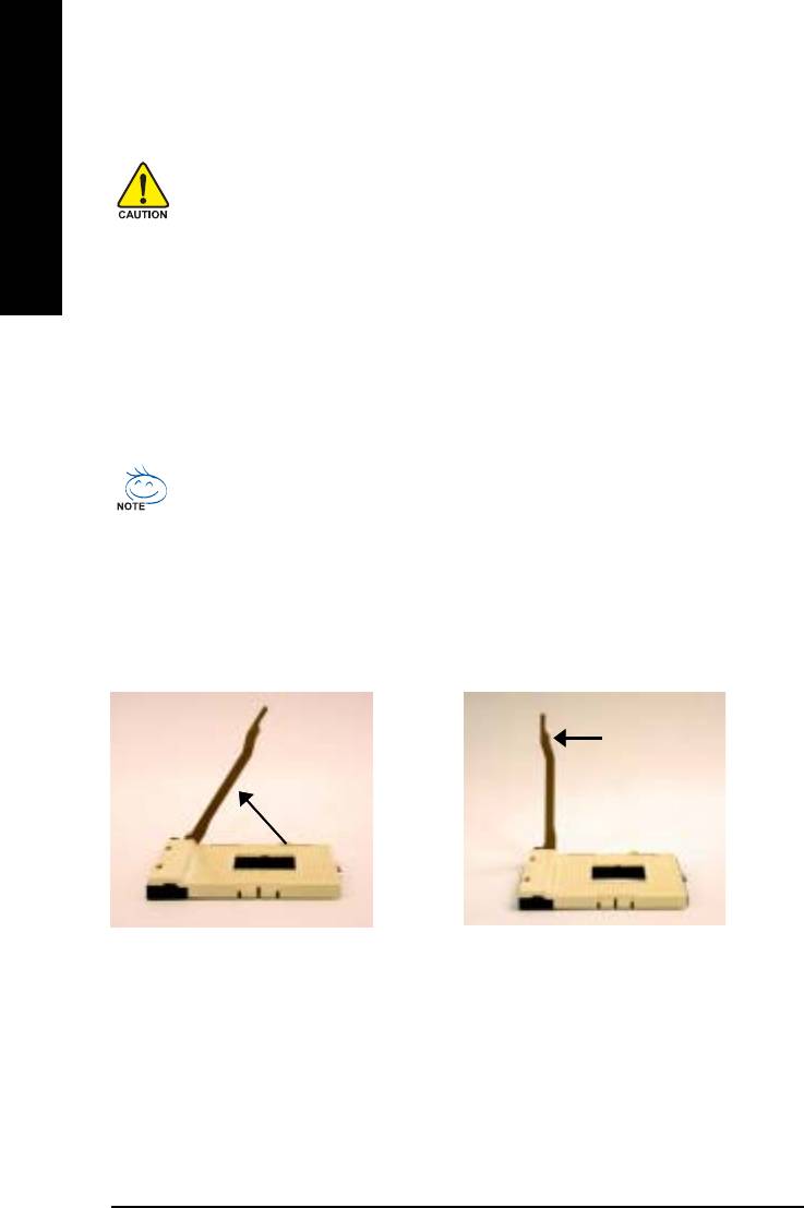
1-3-1 Installation of the CPU
Fully raise the pro-
Raise the processor
cessor socket handle.
socket handle to 65
degrees.
1. Raise the processor socket handle to
2. Raise the processor socket
65 degrees. You maybe feel a kind of
handle all the way up to a fully
tight.
raised position (around 90
degrees) till you hear a "click."
GA-8GEM800 Motherboard - 12 -
English
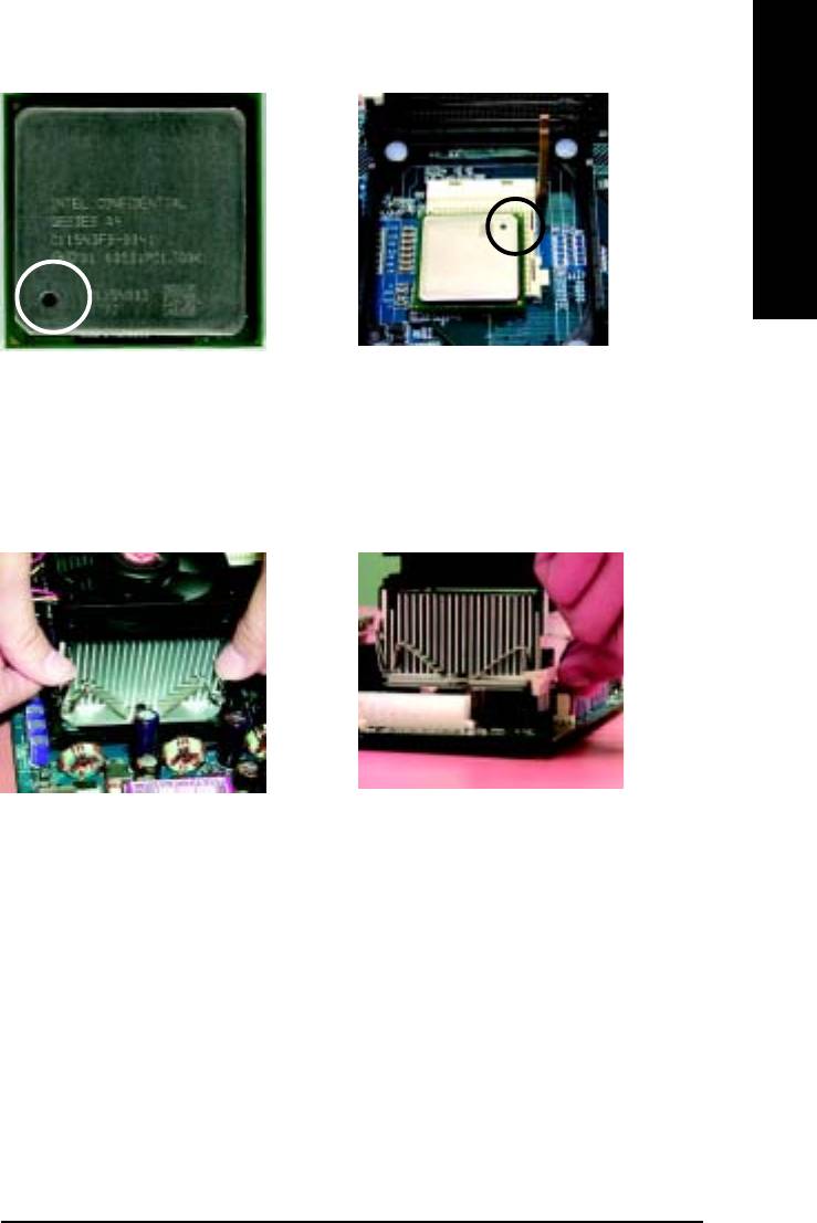
Pin OnePin One
Pin OnePin One
Pin One
IndicatorIndicator
IndicatorIndicator
Indicator
4. Locate Pin One in the socket and
3. Locate the Pin One Indicator on the
look for a (golden) cut edge on the
processor.
CPU upper corner. Then insert the
CPU into the socket and close the
socket handle.
1-3-2 Installation of the Heatsink
1. Push down the cooler clip to secure to the
2. Plug the cooler power cable into the CPU fan
retention mechanism hooks for all four corners.
connector on the motherboard.
®
00
00
0 Please use Intel
approved cooling fan.
0 We recommend you to apply the thermal tape to provide better heat conduc
00
00
tion between your CPU and heatsink. (The CPU cooling fan might stick to the
CPU due to the hardening of the thermal paste. During this condition if you
try to remove the cooling fan, you might pull the processor out of the
CPU socket alone with the cooling fan, and might damage the processor. To
avoid this from happening, we suggest you to either use thermal tape in
stead of thermal paste, or remove the cooling fan with extreme caution.)
0 Make sure the CPU fan power cable is plugged in to the CPU fan connector,
00
00
this completes the installation.
00
00
0 Please refer to CPU heat sink user’s manual for more detail installation
procedure.
Hardware Installation- 13 -
1-4 Installation of Memory
Before installing the memory modules, please comply with the following conditions:
1. Please make sure that the memory used is supported by the motherboard. It is recommended that
English
memory of similar capacity, specifications and brand be used.
2. Before installing or removing memory modules, please make sure that the computer
power is switched off to prevent hardware damage.
3. Memory modules have a foolproof insertion design. A memory module can be
installed in only one direction. If you are unable to insert the module, please switch the
direction.
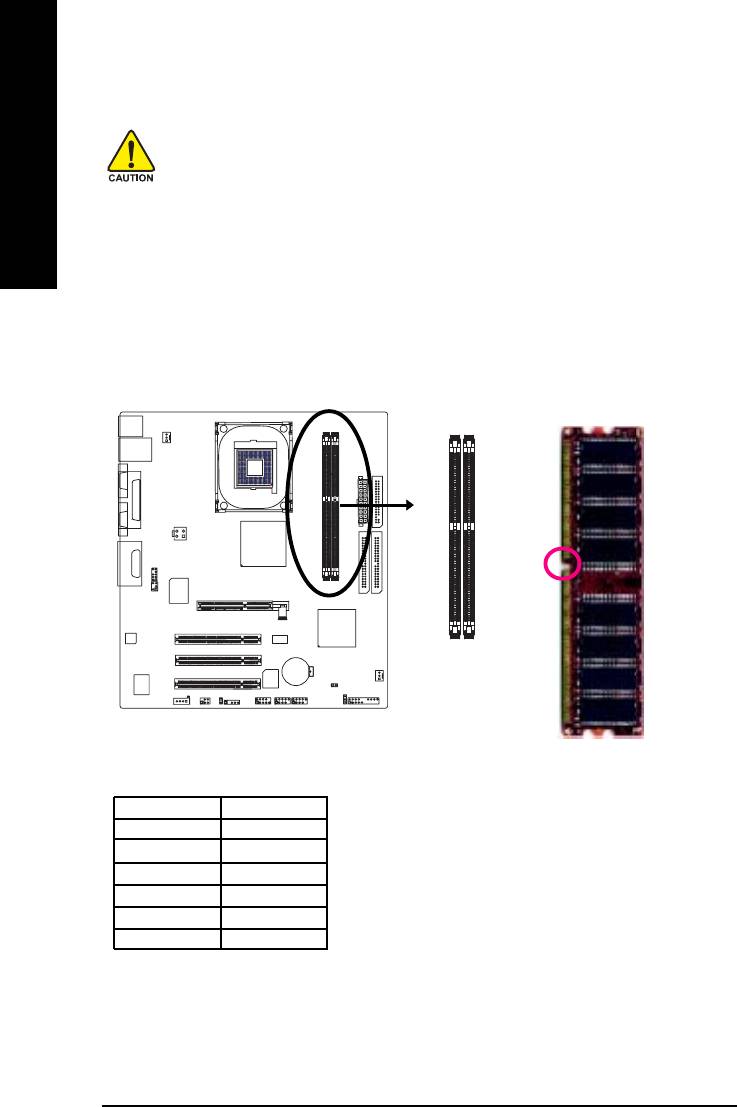
The motherboard has 2 dual inline memory module (DIMM) sockets. The BIOS will automatically
detects memory type and size. To install the memory module, just push it vertically into the DIMM
socket. The DIMM module can only fit in one direction due to the notch. Memory size can vary between
sockets.
notch
55
DDR memory module
DDR1 DDR2
SS
DS
DD
DX
SD
SX
D:Double Sided DIMM S:Single Sided DIMM
X:Not Use
GA-8GEM800 Motherboard - 14 -

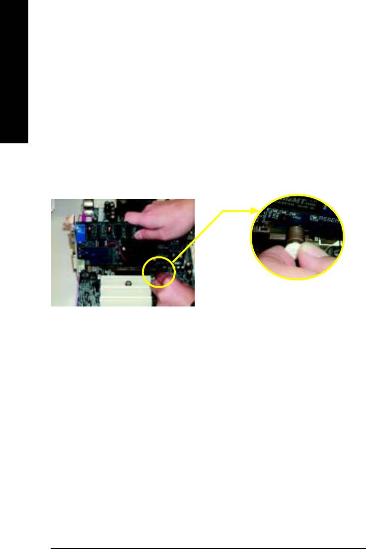
1. The DIMM slot has a notch, so the DIMM
English
memory module can only fit in one direction.
2. Insert the DIMM memory module vertically
into the DIMM slot. Then push it down.
3. Close the plastic clip at both edges of the DIMM
slots to lock the DIMM module.
Reverse the installation steps when you wish
to remove the DIMM module.
Hardware Installation- 15 -
1-5 Installation of Expansion Cards
You can install your expansion card by following the steps outlined below:
1. Read the related expansion card's instruction document before installing the expansion card into
English
the computer.
2. Remove your computer's chassis cover, screws and slot bracket from the computer.
3. Press the expansion card firmly into expansion slot in motherboard.
4. Be sure the metal contacts on the card are indeed seated in the slot.
5. Replace the screw to secure the slot bracket of the expansion card.
6. Replace your computer's chassis cover.
7. Power on the computer, if necessary, setup BIOS utility of expansion card from BIOS.
8. Install related driver from the operating system.
Installing an AGP expansion card:
Please carefully pull out the small white-drawable
bar at the end of the AGP slot when you try to
install/uninstall the VGA card. Please align the VGA
AGP Card
card to the onboard AGP slot and press firmly
down on the slot. Make sure your VGA card is
locked by the small white-drawable bar.
GA-8GEM800 Motherboard - 16 -
English
1-6 I/O Back Panel Introduction
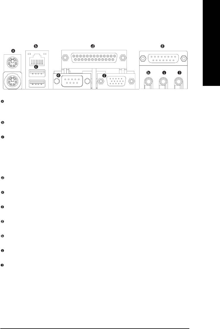
PS/2 Keyboard and PS/2 Mouse Connector
To install a PS/2 port keyboard and mouse, plug the mouse to the upper port (green) and the keyboard to the
lower port (purple).
LAN Port
The LAN port provides Internet connection.
USB port
Before you connect your device(s) into USB connector(s), please make sure your device(s) such
as USB keyboard, mouse, scanner, zip, speaker...etc. have a standard USB interface. Also make
sure your OS supports USB controller. If your OS does not supportUSB controller, please con-
tact OS vendor for possible patch or driver upgrade. For more information please contact your
OS or device(s) vendors.
Parallel Port
The parallel port allows connection of a printer, scanner and other peripheral devices.
Serial Port
Devices like mouses, modems, and etc. can be connected to Serial port.
VGA Port
Monitor can be connected to VGA port.
Game/MIDI Port
This connector supports joystick, MIDI keyboard and other related audio devices.
Line Out (Front Speaker Out)
Connect the stereo speakers, earphone or front surround channels to this connector.
Line In
Devices like CD-ROM, walkman etc. can be connected to Line In jack.
MIC In
Microphone can be connected to MIC In jack.
Hardware Installation- 17 -
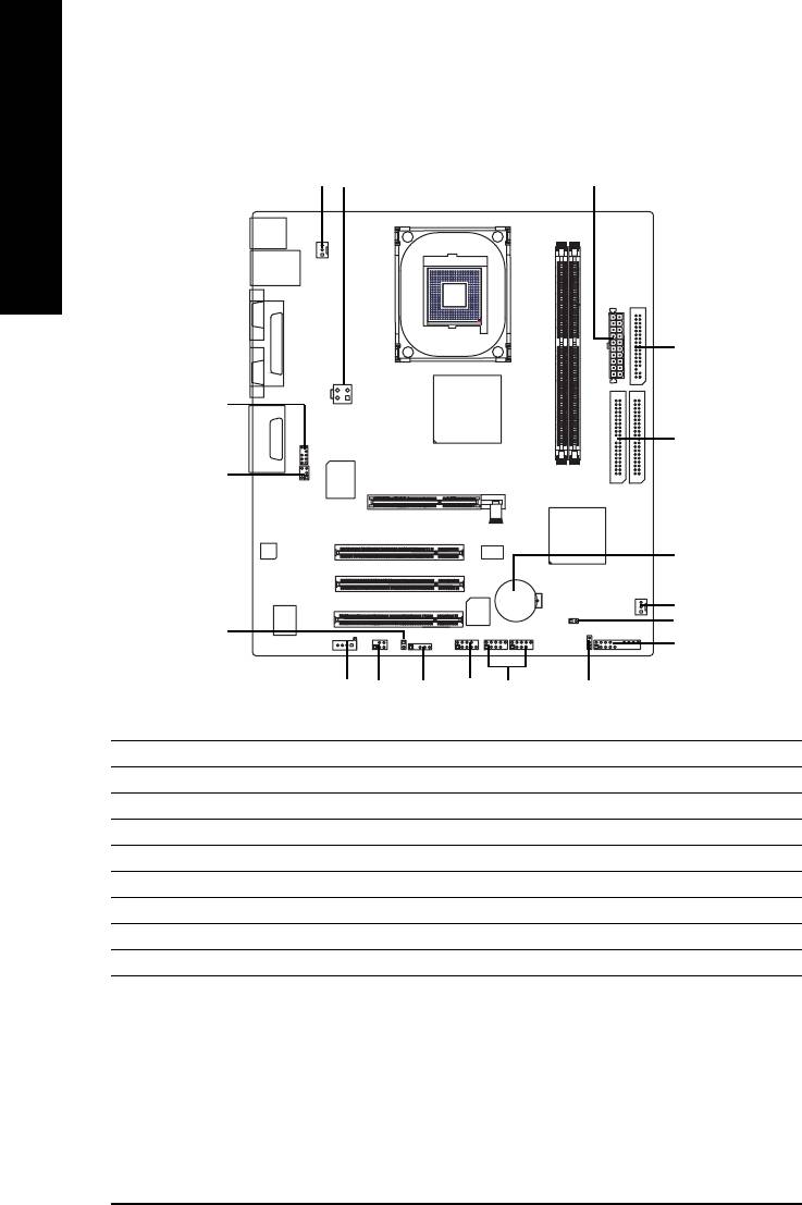
1-7 Connectors Introduction
1
3
4
English
6
8
5
9
18
2
17
14
55
10
11 1315
12
16
7
1) CPU_FAN 10) F_PANEL
2) SYS_FAN 11) CD_IN
3) ATX_12V 12) SPDIF_IO
4) ATX 13) F_USB1/F_USB2
5) IDE1/IDE2 14) CI
6) FDD 15) IR
7) PWR_LED 16) COMB
8) F_AUDIO 17) CLR_CMOS
9) SUR_CEN 18) BAT
GA-8GEM800 Motherboard - 18 -
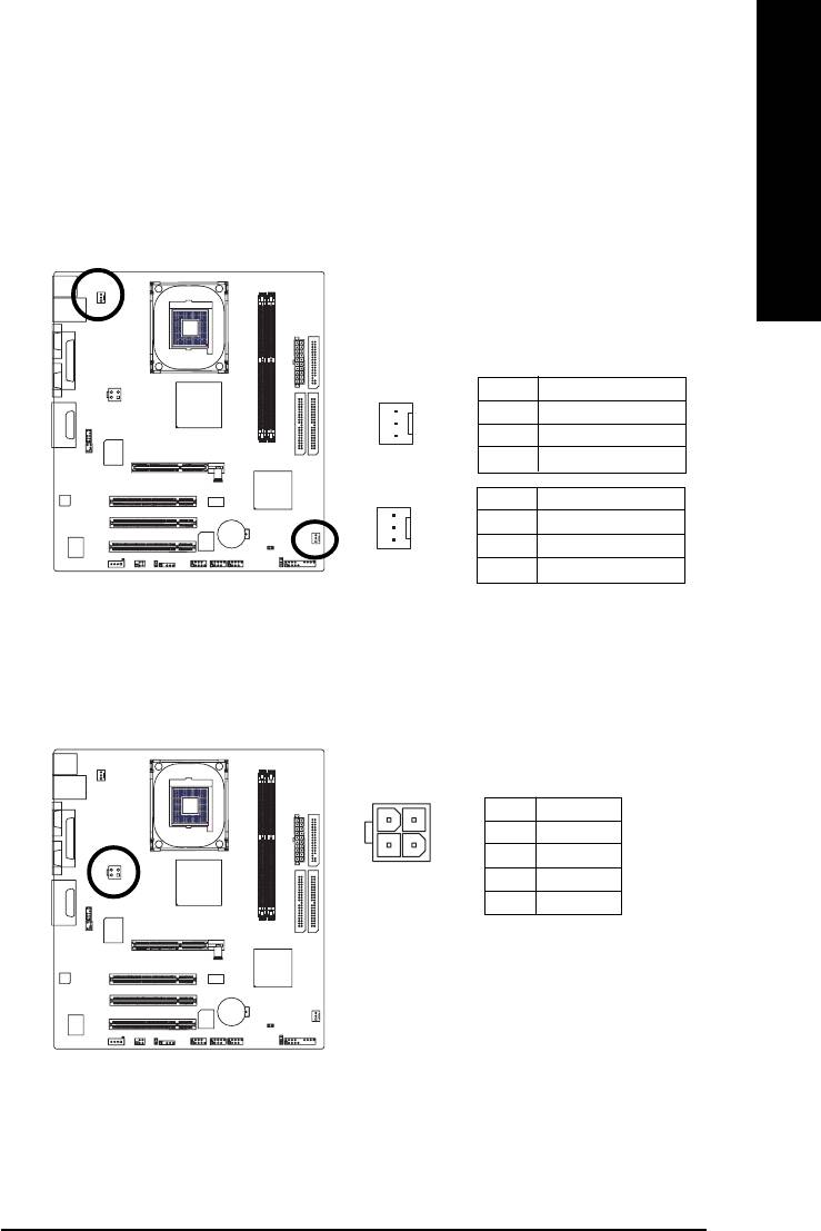
1/2) CPU_FAN / SYS_FAN (CPU Fan Connector/System Fan Connector)
English
Please note, a proper installation of the CPU cooler is essential to prevent the CPU from running
under abnormal condition or damaged by overheating. The CPU fan connector supports max.
current up to 600 mA.
SYS_FAN connector allows you to link with the cooling fan on the system case to lower
the system temperature.
Pin No. Definition
1 GND
1
2 +12V
3 Sense
CPU_FAN
Pin No. Definition
1 GND
1
2 +12V
55
SYS_FAN
3 Sense
3) ATX_12V (+12V Power Connector)
The ATX_12V power connector mainly supplies power to the CPU. If the ATX_12V power
connector is not connected, the system will not start.
Pin No. Definition
4
2
1GND
3
1
2GND
3 +12V
4 +12V
55
Hardware Installation- 19 -
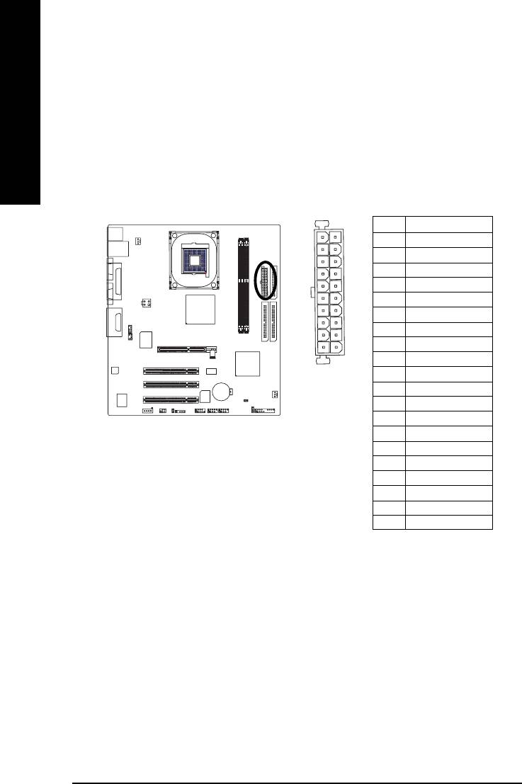
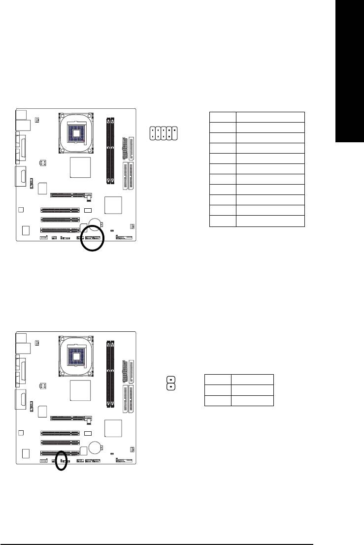
4) ATX (ATX Power)
With the use of the power connector, the power supply can supply enough stable power to all
the components on the motherboard. Before connecting the power connector, please make sure
that all components and devices are properly installed. Align the power connector with its
English
proper location on the motherboard and connect tightly.
Please use a power supply that is able to handle the system voltage requirements. It is
recommended that a power supply that can withstand high power consumption be used (300W
or greater). If a power supply that does not provide the required power is used, the result can
lead to an unstable system or a system that is unable to start.
Pin No. Definition
11
1
1 3.3V
2 3.3V
3 GND
4 VCC
5 GND
6 VCC
7 GND
20
10
8 Power Good
9 5V SB (stand by +5V)
10 +12V
11 3.3V
12 -12V
55
13 GND
14 PS_ON (soft on/off)
15 GND
16 GND
17 GND
18 -5V
19 VCC
20 VCC
GA-8GEM800 Motherboard - 20 -
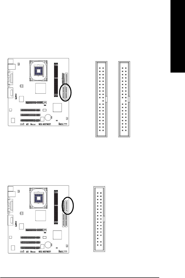
5) IDE1/IDE2 (IDE Connector)
English
An IDE device connects to the computer via an IDE connector. One IDE connector can connect to one
IDE cable, and the single IDE cable can then connect to two IDE devices (hard drive or optical drive). If
you wish to connect two IDE devices, please set the jumper on one IDE device as Master and the other
as Slave(for information on settings, please refer to the instructions located on the IDE device).
40
39
40 39
55
21
21
IDE2 Connector
IDE1 Connector
6) FDD (FDD Connector)
The FDD connector is used to connect the FDD cable while the other end of the cable connects to the
FDD drive. The types of FDD drives supported are: 360KB, 720KB, 1.2MB, 1.44MB and 2.88MB.
Please connect the red power connector wire to the pin1 position.
3334
12
55
Hardware Installation- 21 -
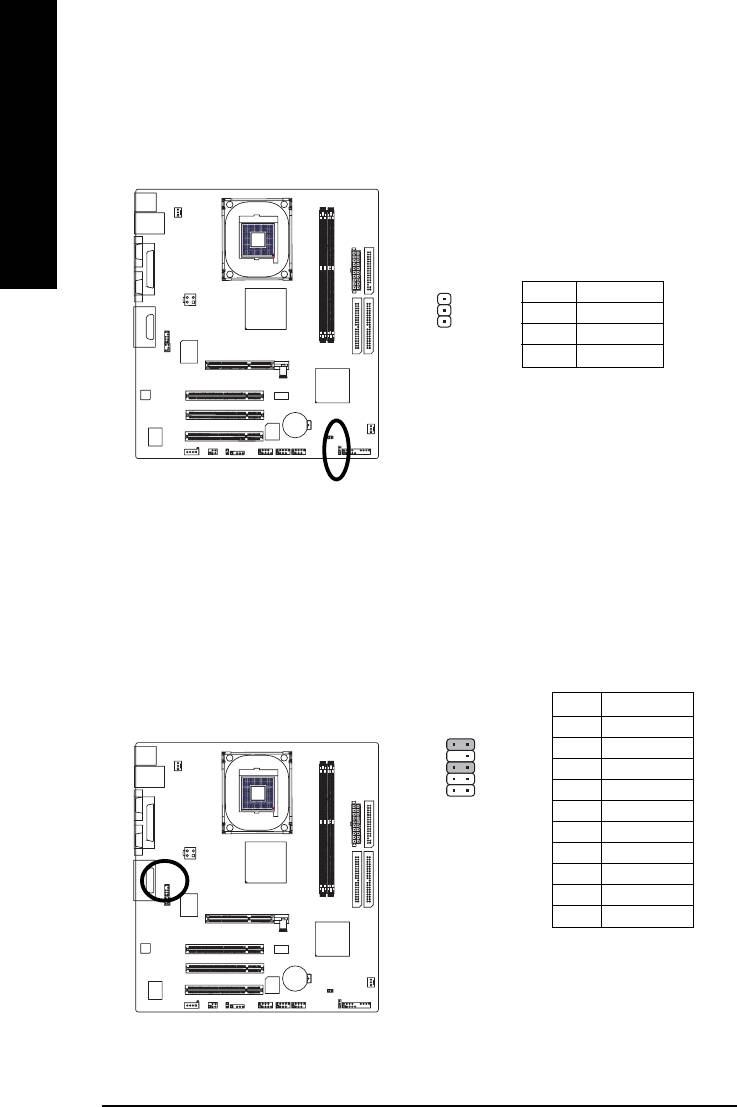
7) PWR_LED
PWR_LED is connected with the system power indicator to indicate whether the system is on/off.
It will blink when the system enters suspend mode.
English
Pin No. Definition
1 MPD+
1
2 MPD-
3 MPD-
55
8) F_AUDIO (Front Audio Panel Connector)
Please make sure the pin assigment on the cable is the same as the pin assigment on the MB header.
To find out if the chassis you are buying support front audio panel connector, please contact your
dealer. If you want to use "Front Audio" connector, you must remove the jumpers on Pin 5-6, 9-10.
Pin No. Definition
1 MIC
10 9
2 GND
3 REF
2
1
4 POWER
5 FrontAudio(R)
6 RearAudio(R)
7 Reserved
8 No Pin
9 FrontAudio (L)
10 RearAudio (L)
55
GA-8GEM800 Motherboard - 22 -
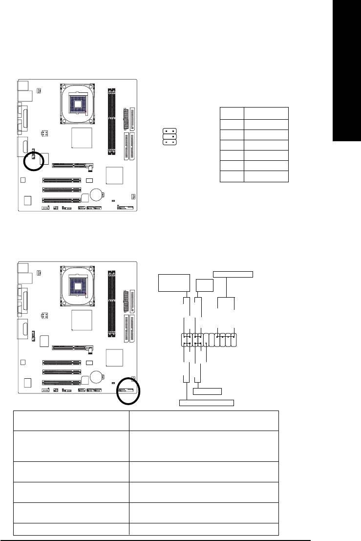
9) SUR_CEN
English
Please contact your nearest dealer for optional SUR_CEN cable.
Pin No. Definition
65
1 SUR OUTL
2 SUR OUTR
3 GND
2
1
4 No Pin
5 CENTER_OUT
6 BASS_OUT
55
10) F_PANEL (Front Panel Jumper)
Please connect the power LED, PC speaker, reset switch and power switch etc. of your chassis
front panel to the F_PANEL connector according to the pin assignment below.
Speaker Connector
Message LED/
Power/
Power
Sleep LED
Switch
PW+
MSG+
MSG-
PW-
SPEAK+
SPEAK-
2
20
1
19
HD-
RES+
NC
HD+
RES-
55
Reset Switch
IDE Hard Disk Active LED
HD (IDE Hard Disk Active LED) Pin 1: LED anode(+)
Pin 2: LED cathode(-)
SPEAK (Speaker Connector) Pin 1: VCC(+)
Pin 2- Pin 3: NC
Pin 4: Data(-)
RES (Reset Switch) Open: Normal Operation
Close: Reset Hardware System
PW (Power Switch) Open: Normal Operation
Close: Power On/Off
MSG(Message LED/Power/Sleep LED) Pin 1: LED anode(+)
Pin 2: LED cathode(-)
NC NC
Hardware Installation- 23 -
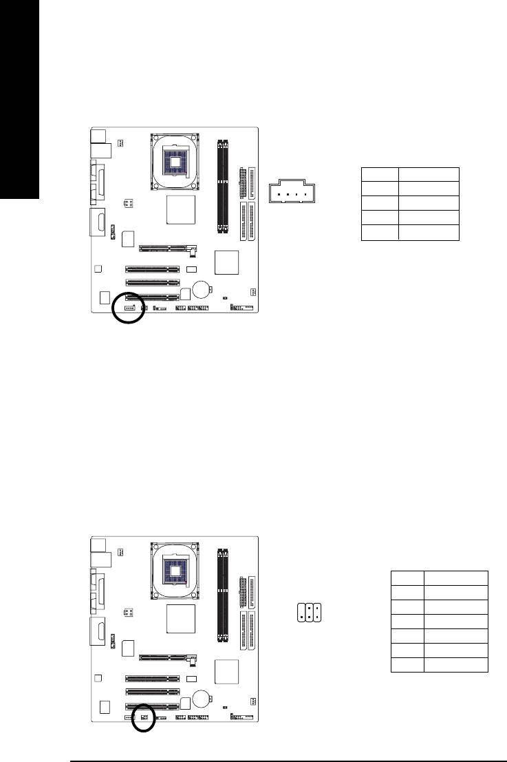
11) CD_IN (CD IN, Black)
Connect CD-ROM or DVD-ROM audio out to the connector.
English
1
Pin No. Definition
1 CD-L
2 GND
3 GND
4 CD-R
55
12) SPDIF_IO (SPDIF In/ Out)
The SPDIF output is capable of providing digital audio to external speakers or compressed AC3
data to an external Dolby Digital Decoder. Use this feature only when your stereo system has
digital input function. Use SPDIF IN feature only when your device has digital output function.
Be careful with the polarity of the SPDIF_IO connector. Check the pin assignment carefully while
you connect the SPDIF_IO cable. Incorrect connection between the cable and connector will
make the device unable to work or even damage it. For optional SPDIF_IO cable, please contact
your local dealer.
Pin No. Definition
1 VCC
62
2 No Pin
3 SPDIF
1
5
4 SPDIFI
5 GND
6 GND
55
GA-8GEM800 Motherboard - 24 -
13) F1_USB / F2_USB (Front USB Connectors, Yellow )
English
Be careful with the polarity of the front USB connector. Check the pin assignment carefully while
you connect the front USB cable, incorrect connection between the cable and connector will make
the device unable to work or even damage it. For optional front USB cable, please contact your
local dealer.
Pin No. Definition
2
10
1 Power
1
1
9
2 Power
3 USB0 DX-
4 USB1 Dy-
5 USB0 DX+
6 USB1 Dy+
7 GND
8 GND
9 No Pin
10 NC
55
14) CI (Chassis Intrusion, Case Open )
This 2-pin connector allows your system to enable or disable the "Case Open" item in BIOS, if the
system case begins remove.
1
Pin No. Definition
1 Signal
2 GND
55
Hardware Installation- 25 -
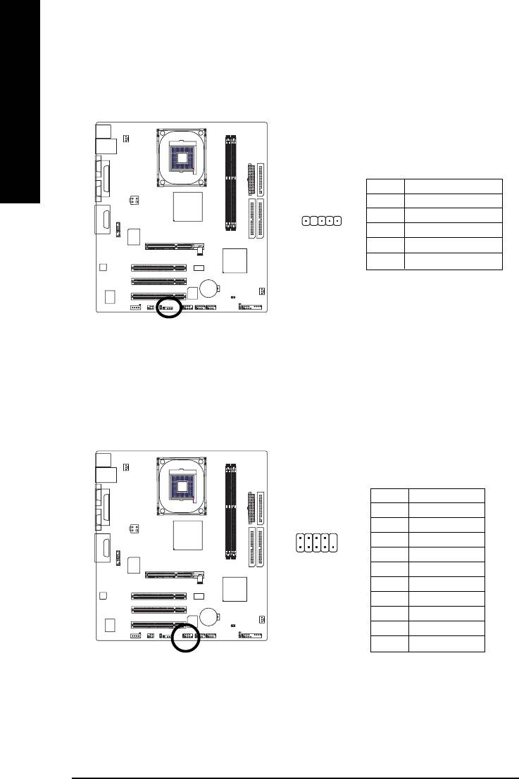
15) IR
Be careful with the polarity of the IR connector while you connect the IR. Please contact you
nearest dealer for optional IR device.
English
Pin No. Definition
1VCC
2 No Pin
1
3 IR RX
4 GND
5 IR TX
55
16) COMB (COMB Connector)
Be careful with the polarity of the COMB connector. Check the pin assignment while you connect
the COMB cable. Please contact your nearest dealer for optional COMB cable.
Pin No. Definition
1 NDCDA-
2
10
2 NSINA
3 NSOUTA
4 NDTRA-
19
5 GND
6 NDSRA-
7 NRTSA-
8 NCTSA-
9 NRIA-
55
10 No Pin
GA-8GEM800 Motherboard - 26 -
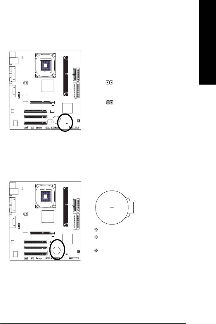
17) CLR_CMOS (Clear CMOS)
English
You may clear the CMOS data to its default values by this jumper. To clear CMOS, temporarily
short 1-2 pin. Default doesn’t include the “Shunter” to prevent improper use of this jumper.
1
Open: Normal
1
Short: Clear CMOS
55
18) BAT (Battery)
Danger of explosion if battery is incorrectly replaced.
Replace only with the same or equivalent type
recommended by the manufacturer.
Dispose of used batteries according to the manufacturer's
55
instructions.
If you want to erase CMOS...
1.Turn off the computer and unplug the power cord.
2.Remove the battery, wait for 30 second.
3.Re-install the battery.
4.Plug the power cord and turn ON the computer.
Hardware Installation- 27 -

English
GA-8GEM800 Motherboard - 28 -


