Gigabyte 8I845GE-RZC: инструкция
Раздел: Компьютерная техника, комплектующие, аксессуары
Тип: Материнская Плата
Инструкция к Материнской Плате Gigabyte 8I845GE-RZC
8I845GE-RZ /
8I845GE-RZ-C
®
®
Intel
Pentium
4 Processor Motherboard
User's Manual
Rev. 1001
12ME-I845GERZ-1001
Copyright
© 2004 GIGABYTE TECHNOLOGY CO., LTD
Copyright by GIGA-BYTE TECHNOLOGY CO., LTD. ("GBT"). No part of this manual may be reproduced or transmitted in any from
without the expressed, written permission of GBT.
Trademarks
Third-party brands and names are the property of their respective owners.
Notice
Please do not remove any labels on motherboard, this may void the warranty of this motherboard.
Due to rapid change in technology, some of the specifications might be out of date before publication of this booklet.
The author assumes no responsibility for any errors or omissions that may appear in this document nor does the author make a
commitment to update the information contained herein.
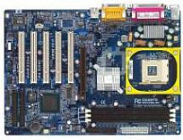
8I845GE-RZ
Mother Board
Oct. 15, 2004
Oct. 15 ,2004
8I845GE-RZ
Motherboard

Preparing Your Computer
Computer motherboards and expansion cards contain very delicate Integrated Circuit (IC) chips. To
protect them against damage from static electricity, you should follow some precautions whenever you
work on your computer.
1. Unplug your computer when working on the inside.
2. Use a grounded wrist strap before handling computer components. If you do not have one,
touch both of your hands to a safely grounded object or to a metal object, such as the power
supply case.
3. Hold components by the edges and try not touch the IC chips, leads or connectors, or other
components.
4. Place components on a grounded antistatic pad or on the bag that came with the components
whenever the components are separated from the system.
5. Ensure that the ATX power supply is switched off before you plug in or remove the ATX power
connector on the motherboard.
Installing the motherboard to the chassis
If the motherboard has mounting holes, but they don't line up with the holes on the base and there
are no slots to attach the spacers, do not become alarmed you can still attach the spacers to the
mounting holes. Just cut the bottom portion of the spacers (the spacer may be a little hard to cut off, so
be careful of your hands). In this way you can still attach the motherboard to the base without worrying
about short circuits. Sometimes you may need to use the plastic springs to isolate the screw from the
motherboard PCB surface, because the circuit wire may be near by the hole. Be careful, don't let the
screw contact any printed circuit write or parts on the PCB that are near the fixing hole, otherwise it
may damage the board or cause board malfunctioning.

Table of Content
English
Chapter 1 Introduction .................................................................................................... 5
Features Summary ..................................................................................................................... 5
8I845GE-RZ Series Motherboard Layout ..................................................................................... 7
Block Diagram ............................................................................................................................ 8
Hardware Installation Process ..................................................................................................... 9
Step 1: Install the Central Processing Unit (CPU) ....................................................................... 9
Step 1-1: CPU Installation .................................................................................................. 10
Step 1-2: CPU Cooling Fan Installation .............................................................................. 10
Step 2: Install Memory Modules ................................................................................................11
Step 3: Install AGP Card .......................................................................................................... 12
Step 4: Install I/O Peripherals Cables ....................................................................................... 12
Step 4-1: I/O Back Panel Introduction ................................................................................ 12
Step 4-2: Connectors Introduction ....................................................................................... 13
Chapter 2 BIOS Setup .................................................................................................. 21
The Main Menu (For example: BIOS Ver. : F1) ........................................................................ 21
Standard CMOS Features ........................................................................................................ 23
Advanced BIOS Features......................................................................................................... 25
Integrated Peripherals............................................................................................................... 27
Power Management Setup ........................................................................................................ 29
PnP/PCI Configurations............................................................................................................ 31
PC Health Status ...................................................................................................................... 32
Frequency/Voltage Control ........................................................................................................ 33
Top Performance ....................................................................................................................... 34
Load Fail-Safe Defaults.............................................................................................................. 34
Load Optimized Defaults ............................................................................................................ 35
Set Supervisor/User Password ................................................................................................ 35
Save & Exit Setup.................................................................................................................... 36
Exit Without Saving .................................................................................................................. 36
Chapter 3 Driver Installation ......................................................................................... 37
8I845GE-RZ Series Motherboard
- 4 -

English
Chapter 1 Introduction
Features Summary
®
®
(note 1)
CPU y Socket 478 for Intel
Pentium
4 (Northwood, Prescott
) processor
with HT Technology
y Supports 533/400MHz FSB
y L2 cache varies with processors
®
Chipset y North Bridge:Intel
845GE
®
y South Bridge: Intel
ICH4
Memory y 3 184-pin DDR sockets
(note 2)
y Supports DDR333/DDR266 DIMMs
y Supports up to 2GB (Max.)
y Supports only 2.5V DDR SDRAM
Slots y 1 AGP slot 4X (1.5V) device support
y 5 PCI slots
IDE Connections y 2 IDE connection (UDMA 33/ATA 66/ATA 100), allows connection of 4
IDE devices
FDD Connections y 1 FDD connection, allows connection of 2 FDD devices
Peripherals y 1 parallel port supporting Normal/EPP/ECP mode
y 1 VGA port, 1 COMA port, onboard COMB connection
y 6 USB 2.0/1.1 ports (rear x 2, front x 4 via cable)
y 1 front audio connector
y 1 PS/2 keyboard port
y 1 PS/2 mouse port
®
Onboard VGA y Built-in Intel
82845GE Chipset
*
Onboard LAN y RLT8100C
*
y 1 RJ45 port
Onboard Audio y C-Media 9761A CODEC
y Supports Line In ; Line Out ; MIC In
y Supports 2 / 4 / 6 channel audio
y Supports SPDIF In/Out connection
y CD In/AUX In/Game Port
BIOS y Use of licensed AWARD BIOS
y Supports Q-Flash
to be continued......
(Note 1) Prescotts processors with up to 533MHz FSB are supported.
(Note 2) Due to (Intel 845PE/GE/GV) chipset architecture limitation, DDR333 memory modules are
supported only when you install a Pentium 4 processor with 533MHz FSB.
A Pentium 4 processor with 400MHz FSB will support DDR266 memory modules.
"*" For 8I845GE-RZ only.
Introduction- 5 -
I/O Control y IT8712
Hardware Monitor y CPU / System fan speed detection
y System voltage detection
y CPU temperature detection
English
y CPU/System fan fail warning
y CPU overheating warning
Additional Features y Supports EasyTune 4
y Supports @BIOS
Form Factor y ATX form factor; 29.5cm x 21cm
Please set the CPU host frequency in accordance with your processor's specifications.
We don't recommend you to set the system bus frequency over the CPU's specification
because these specific bus frequencies are not the standard specifications for CPU,
chipset and most of the peripherals. Whether your system can run under these specific
bus frequencies properly will depend on your hardware configurations, including CPU,
Chipsets, Memory, Cards….etc.
8I845GE-RZ Series Motherboard
- 6 -


