Gigabyte GA-8I865PE-L: инструкция
Раздел: Компьютерная техника, комплектующие, аксессуары
Тип: Материнская Плата
Инструкция к Материнской Плате Gigabyte GA-8I865PE-L
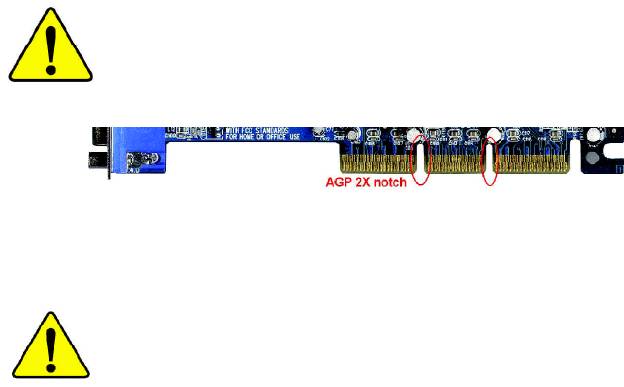
When you installing AGP card, please make sure the following
notice is fully understood and practiced. If your AGP card has
"AGP 4X/8X (1.5V) notch"(show below), please make sure your
AGP card is AGP 4X/8X (1.5V).
AGP 4X/8X notch
®
Caution: AGP 2X card is not supported by Intel
845(GE/PE) / 845(E/
G) / 850(E) / E7205 / 865(G/PE/P) / 875P. You might experience system
unable to boot up normally. Please insert an AGP 4X/8X card.
Example 1: Diamond Vipper V770 golden finger is compatible with 2X/4X
mode AGP slot. It can be switched between AGP 2X(3.3V) or 4X(1.5V)
mode by adjusting the jumper. The factory default for this card is
2X(3.3V). The GA-8I865PE-L (or any AGP 4X/8X only) motherboards might
not function properly, if you install this card without switching the jumper to
4X(1.5V) mode in it.
Example 2: Some ATi Rage 128 Pro graphics cards made by "Power Color",
the graphics card manufacturer & some SiS 305 cards, their golden finger
is compatible with 2X(3.3V)/4X(1.5V) mode AGP slot, but they support 2X
(3.3V) only. The GA-8I865PE-L (or any AGP 4X/8X only) motherboards
might not function properly, If you install this card in it.
Note : Although Gigabyte's AG32S(G) graphics card is based on ATi Rage
128 Pro chip, the design of AG32S(G) is compliance with AGP 4X(1.5V)
®
specification. Therefore, AG32S(G) will work fine with Intel
845(GE/PE) /
845(E/G) / 850(E) / E7205 / 865(G/PE/P) / 875P based motherboards.

M The author assumes no responsibility for any errors
or omissions that may appear in this document nor
does the author make a commitment to update the
information contained herein.
M Third-party brands and names are the property of
their respective owners.
M Please do not remove any labels on motherboard, this
may void the warranty of this motherboard.
M Due to rapid change in technology, some of the
specifications might be out of date before publication
of this booklet.

Declaration of Conformity
We, Manufacturer/Importer
(full address)
G.B.T. Technology Träding GMbH
Ausschlager Weg 41, 1F, 20537 Hamburg, Germany
declare that the product
( description of the apparatus, system, installation to which it refers)
Mother Board
GA-8I865PE
is in conformity with
(reference to the specification under which conformity is declared)
in accordance with 89/336 EEC-EMC Directive
o EN 55011 Limits and methods of measurement
o EN 61000-3-2*
Disturbances in supply systems cause
of radio disturbance characteristics of
T EN 60555-2
by household appliances and similar
industrial,scientific and medical (ISM
electrical equipment “Harmonics”
high frequency equipment
o EN 55013
Limits and methods of measurement
o EN 61000-3-3* Disturbances in supply systems cause
of radio disturbance characteristics of
by household appliances and similar
T EN 60555-3
broadcast receivers and associated
electrical equipment “Voltage fluctuations”
equipment
o EN 55014 Limits and methods of measurement
T EN 50081-1
Generic emission standard Part 1:
of radio disturbance characteristics of
Residual commercial and light industry
household electrical appliances,
portable tools and similar electrical
T EN 50082-1
Generic immunity standard Part 1:
apparatus
Residual commercial and light industry
o EN 55015 Limits and methods of measurement
o EN 55081-2
Generic emission standard Part 2:
of radio disturbance characteristics of
Industrial environment
fluorescent lamps and luminaries
o EN 55020
Immunity from radio interference of
o EN 55082-2
Generic emission standard Part 2:
broadcast receivers and associated
Industrial environment
equipment
T EN 55022 Limits and methods of measurement
o ENV 55104
lmmunity requirements for household
of radio disturbance characteristics of
appliances tools and similar apparatus
information technology equipment
o DIN VDE 0855
Cabled distribution systems; Equipment
o EN50091-2
EMC requirements for uninterruptible
o part 10
for receiving and/or distribution from
power systems (UPS)
o part 12
sound and television signals
T CE marking
(EC conformity marking)
The manufacturer also declares the conformity of above mentioned product
with the actual required safety standards in accordance with LVD 73/23 EEC
o EN 60065
Safety requirements for mains operated
o EN 60950
Safety for information technology equipment
electronic and related apparatus for
including electrical bussiness equipment
household and similar general use
o EN 60335
Safety of household and similar
o EN 50091-1
General and Safety requirements for
electrical appliances
uninterruptible power systems (UPS)
Manufacturer/Importer
Signature:
Timmy Huang
Date : November 28, 2003
Name:
Timmy Huang
(Stamp)

DECLARATION OF CONFORMITY
Per FCC Part 2 Section 2.1077(a)
Responsible Party Name:
G.B.T. INC. (U.S.A.)
Address:
17358 Railroad Street
City of Industry, CA 91748
Phone/Fax No:
(818) 854-9338/ (818) 854-9339
hereby declares that the product
Product Name:
Motherboard
Model Number:
GA-8I865PE
Conforms to the following specifications:
FCC Part 15, Subpart B, Section 15.107(a) and Section 15.109
(a),Class B Digital Device
Supplementary Information:
This device complies with part 15 of the FCC Rules. Operation is
subject to the following two conditions: (1) This device may not
cause harmful and (2) this device must accept any inference received,
including that may cause undesired operation.
Representative Person’s Name:
ERIC LU
Signature:
Eric Lu
Date:
November 28, 2003
GA-8I865PE-L
P4 Titan Series Motherboard
USER'S MANUAL
®
Pentium
4 Processor Motherboard
Rev. 1002
12ME-8I865PEL-1002

Table of Content
English
Warning ..............................................................................................4
Chapter 1 Introduction .........................................................................5
Features Summary .......................................................................................... 5
GA-8I865PE-L Motherboard Layout ............................................................... 8
Block Diagram .................................................................................................. 9
Chapter 2 Hardware Installation Process ............................................ 11
Step 1: Install the Central Processing Unit (CPU) ....................................... 12
Step 1-1: CPU Installation ........................................................................................... 12
Step 1-2 : CPU Cooling Fan Installation ......................................................................13
Step 2: Install memory modules ................................................................... 14
Step 3: Install expansion cards ..................................................................... 17
Step 4: Connect ribbon cables, cabinet wires, and power supply .............. 18
Step 4-1: I/O Back Panel Introduction ..........................................................................18
Step 4-2: Connectors & Jumper Setting Introduction .................................................... 20
Chapter 3 BIOS Setup ....................................................................... 35
The Main Menu (For example: BIOS Ver.: E2) ............................................ 36
Standard CMOS Features ............................................................................. 38
Advanced BIOS Features.............................................................................. 41
Integrated Peripherals .................................................................................. 43
Power Management Setup ............................................................................ 48
- 2 -GA-8I865PE-L Motherboard

Table of Content
English
PnP/PCI Configurations................................................................................. 50
PC Health Status ........................................................................................... 51
Frequency/Voltage Control ............................................................................ 53
Load Fail-Safe Defaults ................................................................................. 56
Load Optimized Defaults ............................................................................... 57
Set Supervisor/User Password ..................................................................... 58
Save & Exit Setup .......................................................................................... 59
Exit Without Saving ...................................................................................... 60
Chapter 4 Technical Reference .......................................................... 63
TM
@ BIOS
Introduction .................................................................................. 63
TM
Easy Tune
4 Introduction ............................................................................ 64
Flash BIOS Method Introduction ................................................................... 65
2-/4-/6-Channel Audio Function Introduction ............................................... 80
Jack-Sensing Introduction ............................................................................. 86
UAJ Introduction ............................................................................................ 88
Xpress Recovery Introduction ....................................................................... 90
Chapter 5 Appendix ........................................................................... 93
- 3 -

Warning
English
Computer motherboards and expansion cards contain very delicate Integrated Circuit (IC) chips. To
protect them against damage from static electricity, you should follow some precautions whenever you
work on your computer.
1. Unplug your computer when working on the inside.
2. Use a grounded wrist strap before handling computer components. If you do not have
one, touch both of your hands to a safely grounded object or to a metal object, such as
the power supply case.
3. Hold components by the edges and try not touch the IC chips, leads or connectors, or
other components.
4. Place components on a grounded antistatic pad or on the bag that came with the
components whenever the components are separated from the system.
5. Ensure that the ATX power supply is switched off before you plug in or remove the ATX
power connector on the motherboard.
Installing the motherboard to the chassis…
If the motherboard has mounting holes, but they don't line up with the holes on the base and there
are no slots to attach the spacers, do not become alarmed you can still attach the spacers to the
mounting holes. Just cut the bottom portion of the spacers (the spacer may be a little hard to cut off, so
be careful of your hands). In this way you can still attach the motherboard to the base without worrying
about short circuits. Sometimes you may need to use the plastic springs to isolate the screw from the
motherboard PCB surface, because the circuit wire may be near by the hole. Be careful, don't let the
screw contact any printed circuit write or parts on the PCB that are near the fixing hole, otherwise it may
damage the board or cause board malfunctioning.
- 4 -GA-8I865PE-L Motherboard

Introduction- 5 -
English
Chapter 1 Introduction
Features Summary
Form Factor — 30.5cm x 23.0cm ATX size form factor, 4 layers PCB.
®
®
CPU — Socket 478 for Intel
Micro FC-PGA2 Pentium
4 processor
®
®
— Support Intel
Pentium
4 (Northwood, Prescott) processor
®
®
— Support Intel
Pentium
4 Processor with HT Technology
®
— Intel Pentium
4 400/533/800MHz FSB
— 2nd cache depends on CPU
Chipset — Chipset Intel 865PE HOST/AGP/Controller
— ICH5 I/O Controller Hub
Memory — 4 184-pin DDR DIMM sockets
— Supports Dual channel DDR400/DDR333/DDR266 DIMM
— Supports 128MB/256MB/512MB/1GB unbuffered DRAM
(Note 1)
— Supports up to 4GB DRAM (Max)
I/O Control — ITE8712
Slots — 1 AGP slot supports 8X/4X mode
— 5 PCI slot supports 33MHz & PCI 2.3 compliant
On-Board IDE — 2 IDE bus master (UDMA33/ATA66/ATA100) IDE ports
for up to 4 ATAPI devices
— Supports PIO mode3,4 (UDMA 33/ATA66/ATA100) IDE
& ATAPI CD-ROM
Serial ATA — Controlled by ICH5
- 2 Serial ATA connectors (SATA0/SATA1) in 150 MB/s
operation mode
to be continued......
Due to chipset (Intel 875P/865G/865PE) architecture limitation, a FSB 800 Pentium 4 processor
will support DDR400/DDR333/DDR266 memory module. A FSB 533 Pentium 4 processor will
support DDR333 and DDR266 memory module. A FSB 400 Pentium 4 processor will only support
DDR 266 memory module.
(Note 1) Due to standard PC architecture, a certain amount of memory is reserved for system
usage and therefore the actual memory size is less than the stated amount.
For example, 4 GB of memory size will instead be shown as 3.xxGB memory during
system startup.

On-Board Peripherals — 1 Floppy port supports 2 FDD with 360K, 720K,1.2M, 1.44M
and 2.88M bytes.
— 1 Parallel port supports Normal/EPP/ECP mode
— 2 Serial ports (COMA&COMB)
English
— 8 USB 2.0/1.1 ports (4 x Rear, 4 xFront by cable)
— 1 Front Audio Connector
— 1 IrDA connector for IR/CIR
Hardware Monitor — CPU/System Fan Revolution detect
— CPU/System Fan Fail Warning
— CPU Overheat Warning
— System Voltage Detect
On-Board Sound — Realtek ALC658 UAJ CODEC
— Support Jack-Sensing
— Line Out / 2 front speaker
— Line In / 2 rear speaker(by s/w switch)
— Mic In / center& subwoofer(by s/w switch)
— SPDIF Out /SPDIF In
— CD_In/ AUX_IN/ Game Connector
On-Board LAN — Build in Kinnereth-R Chipset (10/100 Mbit)
— 1 RJ45 port
PS/2 Connector — PS/2 Keyboard interface and PS/2 Mouse interface
BIOS — Licensed AWARD BIOS
— Supports Q-Flash
to be continued......
- 6 -GA-8I865PE-L Motherboard

Introduction- 7 -
English
Additional Features — PS/2 Keyboard power on by password
— PS/2 Mouse power on
— STR(Suspend-To-RAM)
— AC Recovery
— USB KB/Mouse wake up from S3
— Supports EasyTune 4
— Supports @BIOS
Overclocking — Over Voltage (DDR/AGP/CPU) by BIOS
— Over Clock (DDR/AGP/CPU/PCI) by BIOS
HT functionality requirement content :
Enabling the functionality of Hyper-Threading Technology for your computer system requires
all of the following platform components:
®
- CPU: An Intel
Pentium 4 Processor with HT Technology
®
- Chipset: An Intel
Chipset that supports HT Technology
- BIOS: A BIOS that supports HT Technology and has it enabled
- OS: An operation system that has optimizations for HT Technology
Please set the CPU host frequency in accordance with your processor's specifications.
We don't recommend you to set the system bus frequency over the CPU's specification
because these specific bus frequencies are not the standard specifications for CPU,
chipset and most of the peripherals. Whether your system can run under these specific
bus frequencies properly will depend on your hardware configurations, including CPU,
Chipsets, Memory, Cards… .etc.
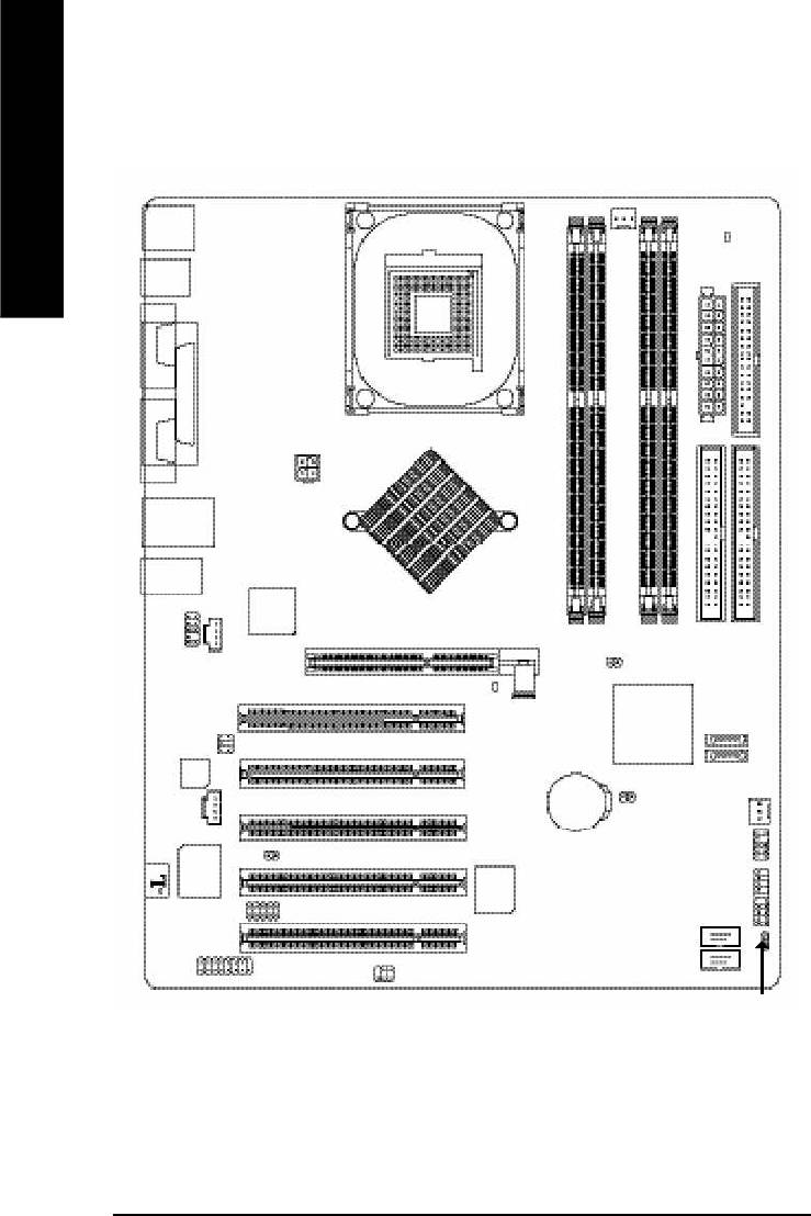
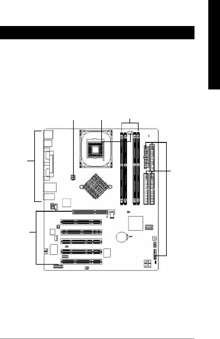
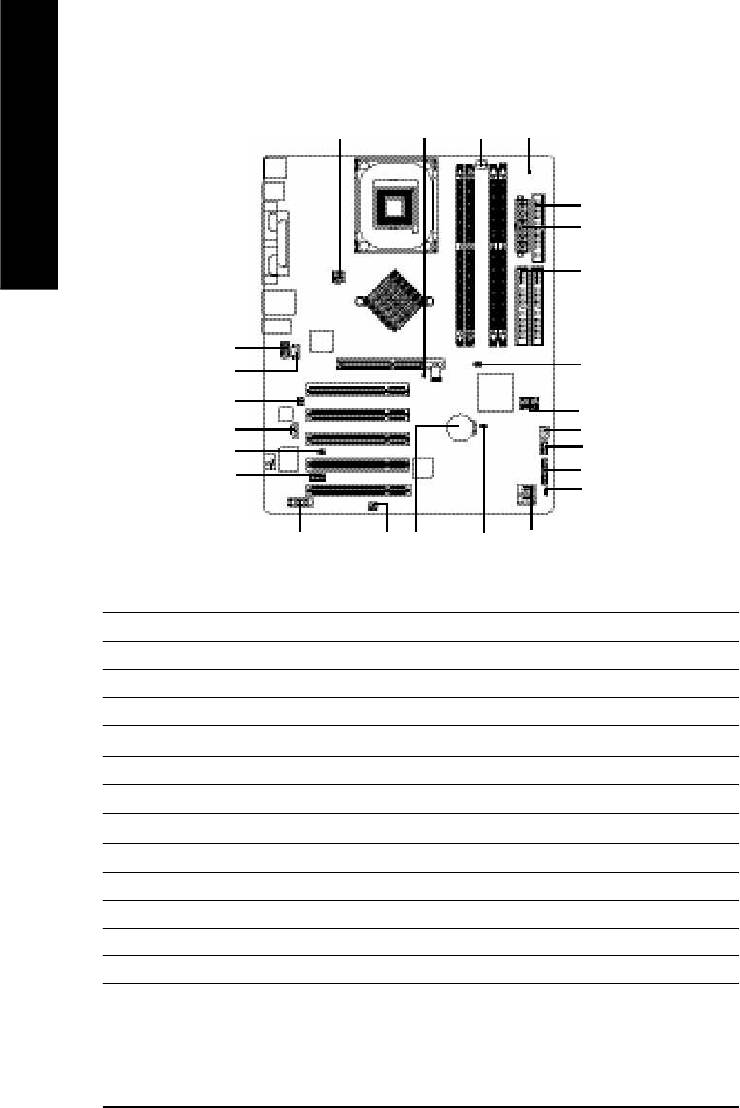
GA-8I865PE-L Motherboard Layout
English
RAM_LED
KB_M S
R_USB
CPU_FAN
ATX
FDD
COMACOMB
Hyper Threading
SOC KET4 78
LPT
ATX_ 12 V
IDE1
USB
LAN
Kinnereth-R
GA-8I865PE
MIC_IN
LINE_OUT
LINE_IN
®
Intel
865PE
DDR1
DDR2
AGP
CD_IN
IDE2
CLR_PWD
DDR3
DDR4
F_AUDIO
2X_DET
ICH5
SATA 1
PCI1
SUR_C EN
P4 Titan
CODEC
SATA 0
PCI2
AUX_IN
BAT
CLR_CMOS
SYS_FAN
PCI3
INFO_LINK
CI
ITE8712
BIOS
F_PAN EL
PCI4
IR_CIR
F_U SB2
PCI5
F_U SB1
GAM E
SPDIF_IO
PWR_LED
- 8 -GA-8I865PE-L Motherboard
- 9 - Hardware Installation Process
English
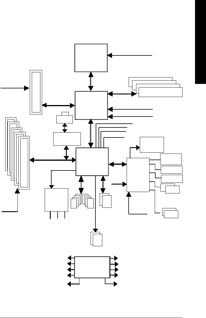
Block Diagram
Pentium 4
CPUCLK+/- (100/133/200MHz)
Socket 478
CPU
AGP 8X/4X
AGPCLK
System Bus
(66MHz)
400/533/800MHz
DDR
266/333/400MHz
Intel 865PE
ZCLK (66MHz)
5 PCI
HCLK+/- (100/133MHz)
RJ45
66MHz
33 MHz
14.318 MHz
48 MHz
Kinnereth-R
BIOS
ICH5
Game Port
LPC BUS
Floppy
ITE8712
AC97 Link
24 MHz
LPT Port
AC97
PS/2
PCICLK
CODEC
KB/Mouse
(33MHz)
ATA33/66/100
33 MHz
8 USB
IDE Channels
(2.0/1.1)
COM
MIC
Ports
Ports
LINE-IN
LINE-OUT
Serial ATA
Channels
PCICLK (33MHz)
ZCLK (66MHz)
USBCLK (48MHz)
CLK GEN
CPUCLK+/- (100/133/200MHz)
14.318 MHz
AGPCLK (66MHz)
33 MHz
HCLK+/- (100/133MHz)
24 MHz
ICH3V66 (66MHz)

English
- 10 -GA-8I865PE-L Motherboard
- 11 - Hardware Installation Process
English
Chapter 2 Hardware Installation Process
To set up your computer, you must complete the following steps:
Step 1- Install the Central Processing Unit (CPU)
Step 2- Install memory modules
Step 3- Install expansion cards
Step 4- Connect ribbon cables, cabinet wires, and power supply
Step 2
Step 4
Step 1
Step 4
Step 4
Step 3
Congratulations you have accomplished the hardware installation!
Turn on the power supply or connect the power cable to the power outlet. Continue with
the BIOS/software installation.
Note: If the NorthBridge on the motherboard has a fan sink, then the motherboard contains a
NB_FAN connector.
Step 1: Install the Central Processing Unit (CPU)
Before installing the processor, adhere to the following warning:
English
If you do not match the CPU socket Pin 1 and CPU cut edge well, it will
cause improper installation. Please change the insert orientation.
Please make sure the CPU type is supported by the motherboard.
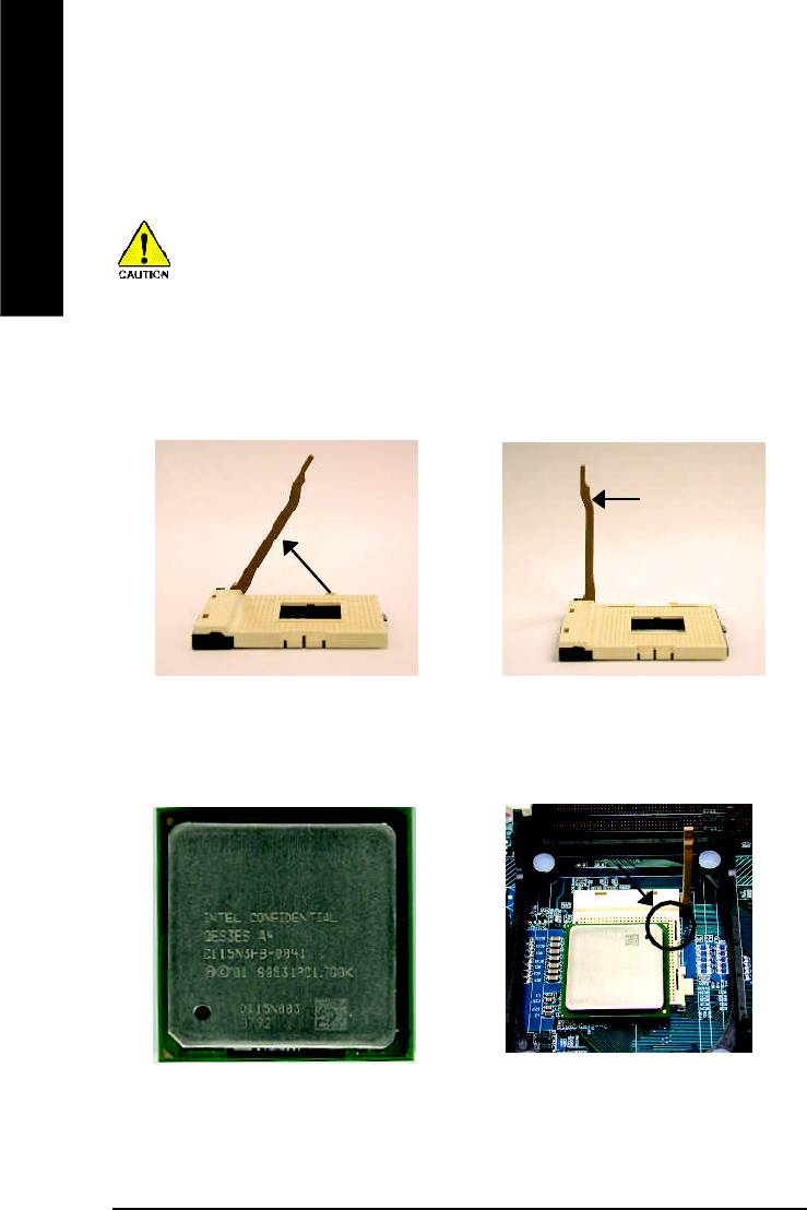
Step 1-1: CPU Installation
Angling the
Socket
0
r o d t o 6 5
Actuation
Lever
1. Angling the rod to 65-degree maybe feel a
2. Pull the rod to the 90-degree directly.
kind of tight, and then continue pull the rod
to 90-degree when a noise "cough" made.
Pin1 indicator
Pin1 indicator
4. Locate Pin 1 in the socket and look
3. CPU Top View
for a (golden) cut edge on the CPU
upper corner. Then insert the CPU
into the socket.
- 12 -GA-8I865PE-L Motherboard
- 13 - Hardware Installation Process
English
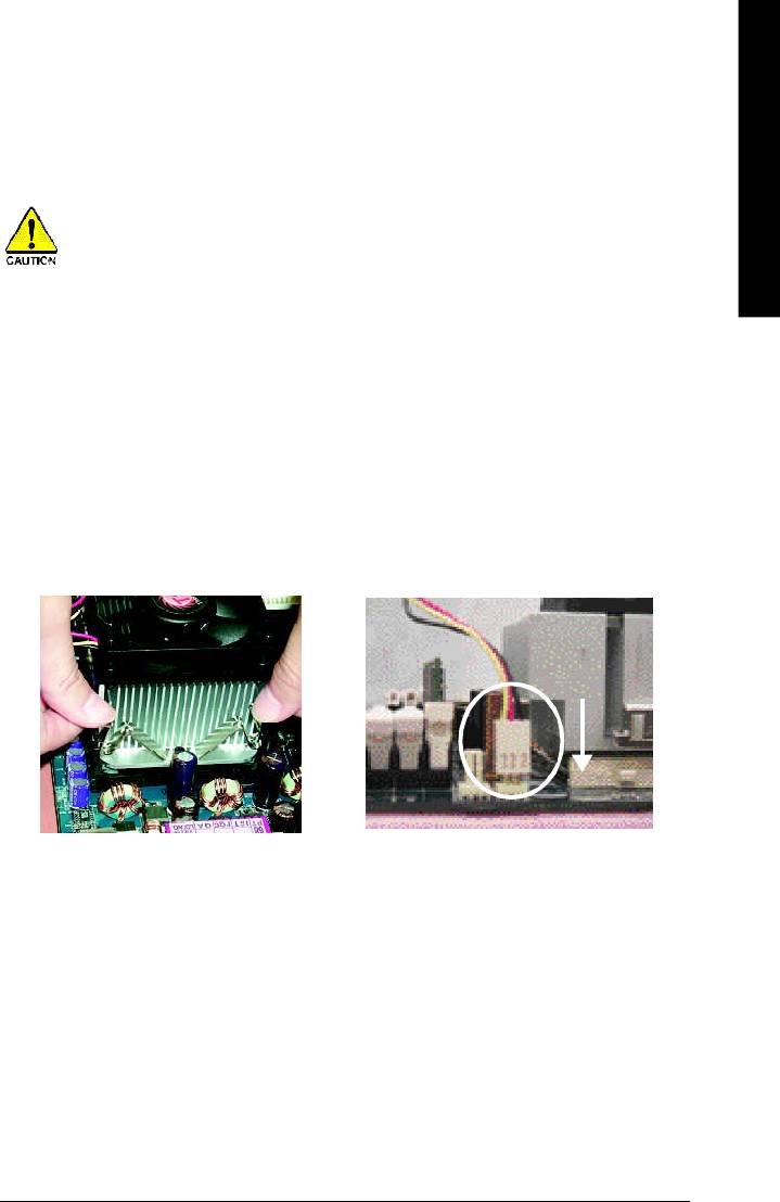
Step 1-2 : CPU Cooling Fan Installation
Before installing the CPU Cooling Fan , adhere to the following warning:
1. Please use Intel approved cooling fan.
2. We recommend you to apply the thermal tape to provide better heat conduction
between your CPU and cooling fan.
(The CPU cooling fan might stick to the CPU due to the hardening of the thermal
paste. During this condition if you try to remove the cooling fan, you might pull the
processor out of the CPU socket alone with the cooling fan, and might damage the
processor. To avoid this from happening, we suggest you to either use thermal
tape instead of thermal paste, or remove the cooling fan with extreme caution.)
3. Make sure the CPU fan power cable is plugged in to the CPU fan connector, this
completes the installation.
Please refer to CPU cooling fan user's manual for more detail installation procedure.
2. Make sure the CPU fan is plugged to
1. Fasten the cooling fan supporting-base
the CPU fan connector, than install
onto the CPU socket on the
complete.
mainboard.
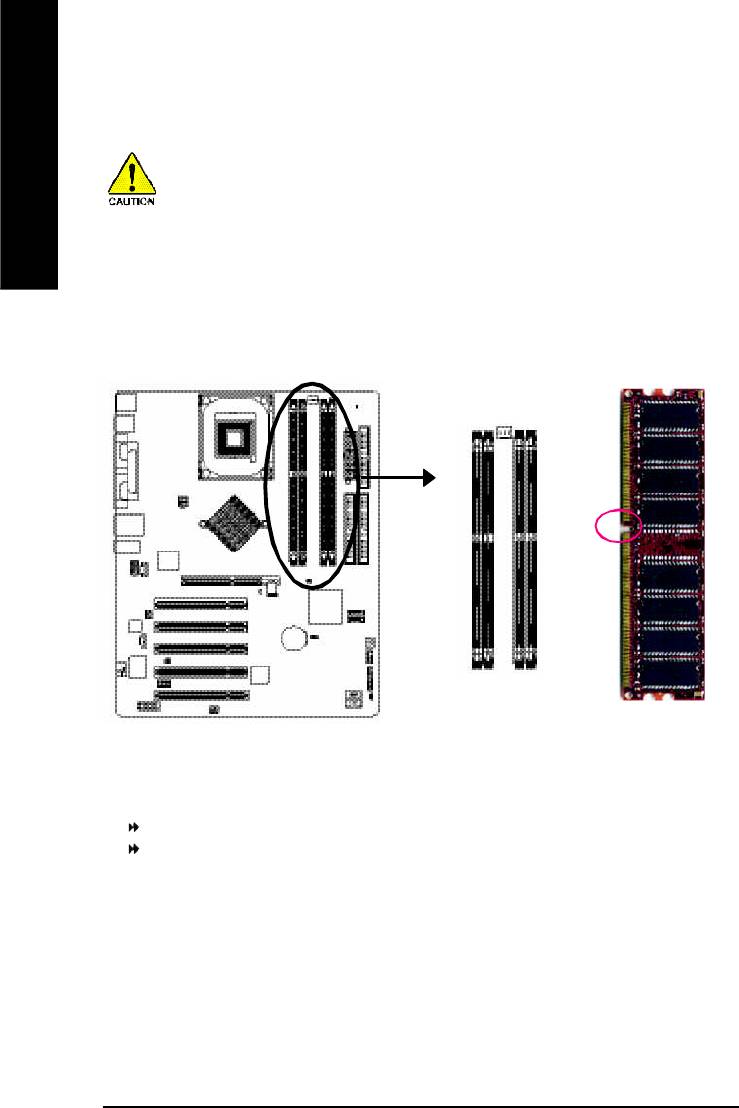
Step 2: Install memory modules
Before installing the processor and heatsink, adhere to the following warning:
English
When RAM_LED is ON, do not install/remove DIMM from socket.
Please note that the DIMM module can only fit in one direction due to the one notches.
Wrong orientation will cause improper installation. Please change the insert orientation.
The motherboard has 4 dual inline memory module (DIMM) sockets. The BIOS will automatically
detects memory type and size. To install the memory module, just push it vertically into the DIMM
socket. The DIMM module can only fit in one direction due to the notch. Memory size can vary
between sockets.
Notch
DDR
GA-8I865PE-L supports the Dual Channel Technology. After operating the Dual Channel Technology,
the bandwidth of Memory Bus will add double up to 6.4GB/s.
GA-8I865PE-L includes 4 DIMM sockets, and each Channel has two DIMM sockets as following:
Channel A : DIMM 1, DIMM 2
Channel B : DIMM 3, DIMM 4
If you want to operate the Dual Channel Technology, please note the following explanations due
®
to the limitation of Intel
chipset specifications.
1. Only one DDR memory module is installed: The Dual Channel Technology can't operate
when only one DDR memory module is installed.
- 14 -GA-8I865PE-L Motherboard

- 15 - Hardware Installation Process
English
2. Two DDR memory modules are installed (the same memory size and type): The Dual
Channel Technology will operate when two memory modules are inserted individually into
Channel A and B. If you install two memory modules in the same channel, the Dual Channel
Technology will not operate.
3. Three DDR memory modules are installed: Please note that The Dual Channel
Technology will not operate when three DDR memory modules are installed; part of
them will not be detected.
4. Four DDR memory modules are installed: If you install four memory modules at the same
time, the Dual Channel Technology will operate only when those modules have the same
memory size and type.
We'll strongly recommend our user to slot two DDR memory modules into the DIMMs with the
same color in order for Dual Channel Technology to work.
The following tables include all memory-installed combination types:
(Please note that those types not in the tables will not boot up.)
l Figure 1: Dual Channel Technology (DS: Double Side, SS: Single Side)
DIMM 1 DIMM 2 DIMM 3 DIMM 4
2 memory modules
DS/SS X DS/SS X
X DS/SS X DS/SS
4 memory modules
DS/SS DS/SS DS/SS DS/SS
l Figure 2: Don't operate Dual Channel Technology (DS: Double Side, SS: Single Side)
DIMM 1 DIMM 2 DIMM 3 DIMM 4
1 memory module
DS/SS X X X
X DS/SS X X
X X DS/SS X
X X X DS/SS
2 memory modules
DS/SS DS/SS X X
X X DS/SS DS/SS
3 memory modules
DS/SS DS/SS DS/SS X
DS/SS DS/SS X DS/SS
DS/SS X DS/SS DS/SS
X DS/SS DS/SS DS/SS
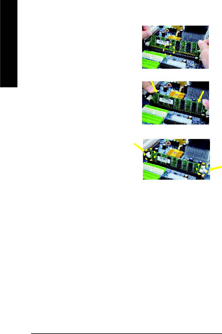
1. The DIMM slot has a notch, so the DIMM
memory module can only fit in one direction.
English
2. Insert the DIMM memory module vertically into
the DIMM slot. Then push it down.
3. Close the plastic clip at both edges of the DIMM
slots to lock the DIMM module.
Reverse the installation steps when you wish
to remove the DIMM module.
DDR Introduction
Established on the existing SDRAM infrastructure, DDR (Double Data Rate) memory is a high
performance and cost-effective solution that allows easy adoption for memory vendors, OEMs,
and system integrators.
DDR memory is a great evolutionary solution for the PC industry that builds on the existing
SDRAM architecture, yet make the awesome advances in solving the system performance
bottleneck by doubling the memory bandwidth. Nowadays, with the highest bandwidth of 3.2GB/
s of DDR400 memory and complete line of DDR400/333/266/200 memory solutions, DDR memory
is the best choice for building high performance and low latency DRAM subsystem that are
suitable for servers, workstations, and full range of desktop PCs.
- 16 -GA-8I865PE-L Motherboard
- 17 - Hardware Installation Process
English
Step 3: Install expansion cards
1. Read the related expansion card's instruction document before install the expansion card into
the computer.
2. Remove your computer's chassis cover, necessary screws and slot bracket from the computer.
3. Press the expansion card firmly into expansion slot in motherboard.
4. Be sure the metal contacts on the card are indeed seated in the slot.
5. Replace the screw to secure the slot bracket of the expansion card.
6. Replace your computer's chassis cover.
7. Power on the computer, if necessary, setup BIOS utility of expansion card from BIOS.
8. Install related driver from the operating system.
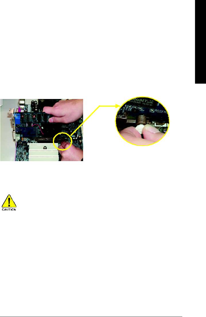
Please carefully pull out the small white- drawable bar
at the end of the AGP slot when you try to install/
Uninstall the AGP card. Please align the AGP card to
AGP Card
the onboard AGP slot and press firmly down on the slot
.Make sure your AGP card is locked by the small white-
drawable bar.
When an AGP 2x (3.3V) card is installed the 2X_DET will light up, indicating a non-supported
graphics card is inserted. Informing users that system might not boot up normally due to AGP 2x
(3.3V) is not supported by the chipset.
Step 4: Connect ribbon cables, cabinet wires, and power
supply
English
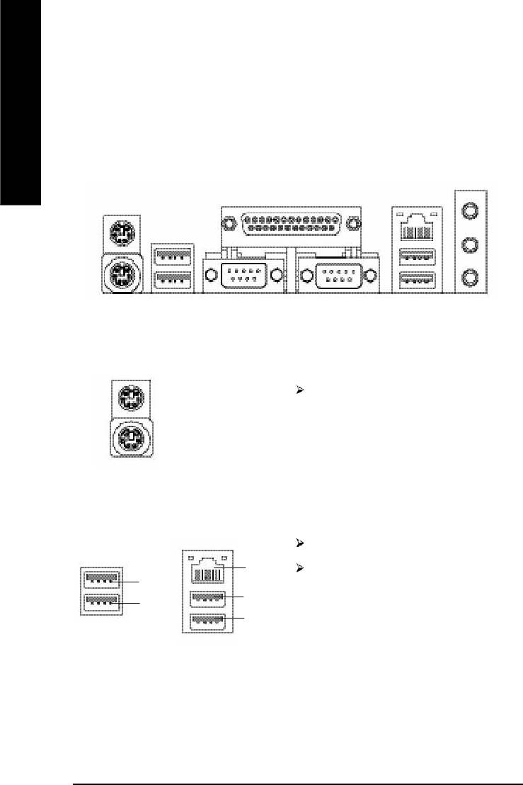
Step 4-1: I/O Back Panel Introduction
y
w x
u
v
u PS/2 Keyboard and PS/2 Mouse Connector
PS/2 Mouse Connector
This connector supports standard PS/2
(6 pin Female)
keyboard and PS/2 mouse.
PS/2 Keyboard Connector
(6 pin Female)
v/x USB / LAN Connector
LAN is fast Ethernet with 10/100Mbps speed.
LAN
Before you connect your device(s) into USB
USB 3
connector(s), please make sure your
USB 4
USB 2
device(s) such as USB keyboard,mouse,
USB 5
scanner, zip, speaker..etc. Have a standard
USB interface. Also make sure your OS
supports USB controller.
If your OS does not support USB controller,
please contact OS vendor for possible patch
or driver upgrade. For more information
please contact your OS or device(s) vendors.
- 18 -GA-8I865PE-L Motherboard
- 19 - Hardware Installation Process
English
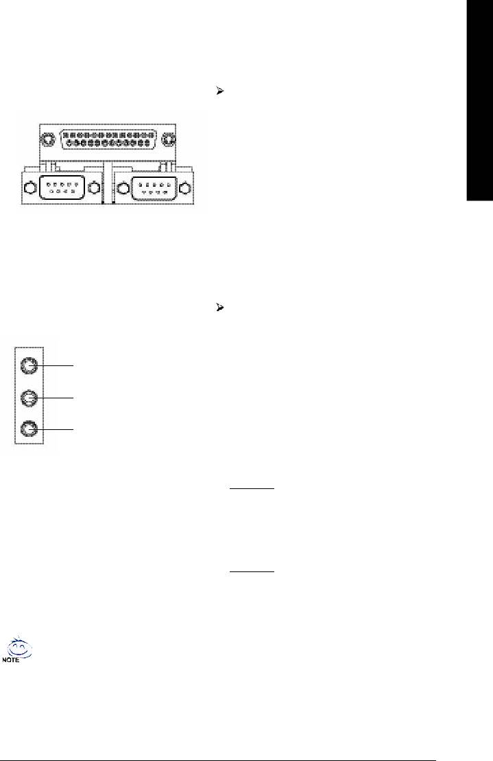
w Parallel Port and Serial Ports (COMA/COMB)
Parallel Port
This connector supports 2 standard COM ports
(25 pin Female)
and 1 Parallel port. Device like printer can be
connected to Parallel port ; mouse and modem
etc can be connected to Serial ports.
COMA
COMB
Serial Port (9 pin Male)
y Audio Connectors
After install onboard audio driver, you may
connect speaker to Line Out jack, micro
phone to MIC In jack.
Device like CD-ROM , walkman etc can be
Line In(Rear Speaker)
connected to Line-In jack.
Please note:
Line Out(Front Speaker)
You are able to use 2-/4-/6- channel audio
feature by S/W selection.
MIC In(Center and Subwoofer)
If you want to enable 6-channel function, you
have 2 choose for hardware connection.
Method1:
Connect "Front Speaker" to "Line Out"
Connect "Rear Speaker" to "Line In"
Connect "Center and Subwoofer" to "MIC
Out".
Method2:
You can refer to page 27, and contact your
nearest dealer for optional SUR_CEN cable.
If you want the detail information for 2-/4-/6-channel audio setup
installation, please refer to page 80.
Step 4-2: Connectors & Jumper Setting Introduction
1
9
3
7
English
6
2
5
12
23
14
13
21
15
4
20
22
10
17
8
19
16
18
11
24
1) ATX_12V 14) CD_IN
2) ATX 15) AUX_IN
3) CPU_FAN 16) SPDIF_IO
4) SYS_FAN 17) IR_CIR
5) IDE1/IDE2 18) F_USB1/F_USB2
6) FDD 19) GAME
7) RAM_LED 20) INFO_LINK
8) PWR_LED 21) SATA0/SATA1
9) 2X_DET 22) CI
10) F_PANEL 23) CLR_PWD
11) BAT 24) CLR_CMOS
12) F_AUDIO
13) SUR_CEN
- 20 -GA-8I865PE-L Motherboard
- 21 - Hardware Installation Process
English
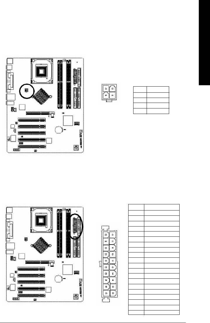
1) ATX_12V (+12V Power Connector)
This connector (ATX _12V) suppliesthe CPU operation voltage (Vcore). If this " ATX_ 12V connector" is
not connected, system cannot boot.
2
1
Pin No. Definition
1 GND
4
3
2 GND
3 +12V
4 +12V
2) ATX (ATX Power)
AC power cord should only be connected to your power supply unit after ATX power cable and other
related devices are firmly connected to the mainboard.
Pin No. Defi n i tio n
1 3.3V
2 3.3V
3 GND
4 VC C
5 GND
11
1
6 VC C
7 GND
8 Power Good
9 5V SB(stan d b y +5 V)
1 0 +12V
11 3.3V
1 2 -12V
1 3 GND
1 4 PS_ON(softO n/ Off)
1 5 GND
1 6 GND
20
10
1 7 GND
1 8 -5V
1 9 VC C
2 0 VC C
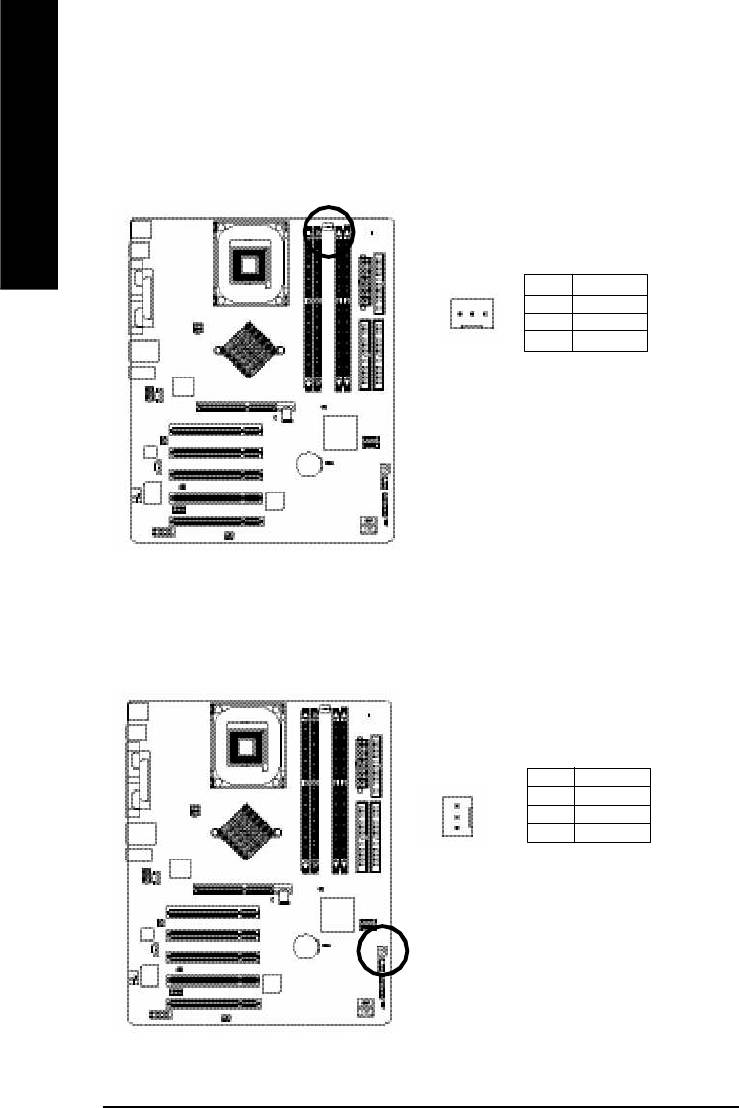
3) CPU_FAN (CPU FAN Connector)
Please note, a proper installation of the CPU cooler is essential to prevent the CPU from running
under abnormal condition or damaged by overheating.The CPU fan connector supports Max.
current up to 600 mA.
English
Pin No. Definition
1 GND
1
2 +12V
3 Sense
4) SYS_FAN (System FAN Connector)
This connector allows you to link with the cooling fan on the system case to lower the system
temperature.
Pin No. Definition
1 GND
2 +12V
1
3 Sense
- 22 -GA-8I865PE-L Motherboard
- 23 - Hardware Installation Process
English
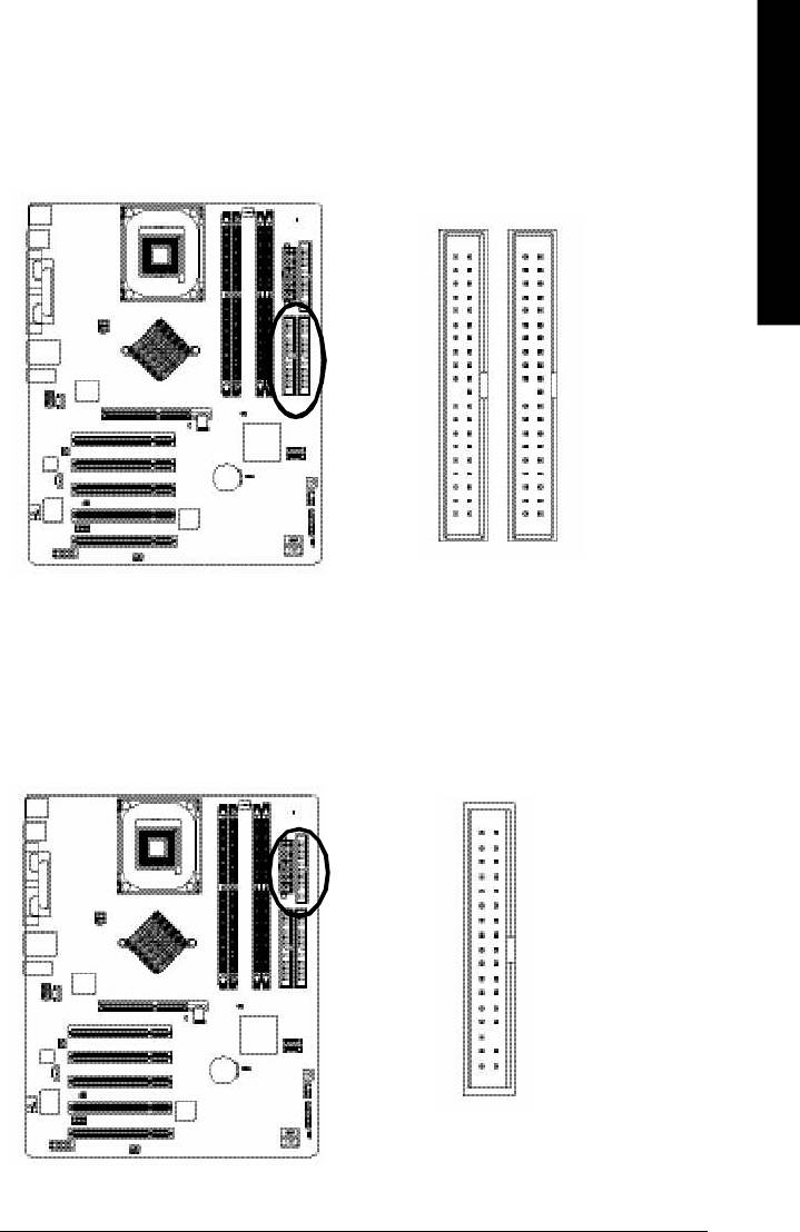
5) IDE1/ IDE2(IDE1/IDE2 Connector)
Please connect first harddisk to IDE1 and connect CDROM to IDE2. The red stripe of the ribbon cable
must be the same side with the Pin1.
40
39
2
1
IDE2
IDE1
6) FDD (Floppy Connector)
Please connect the floppy drive ribbon cables to FDD. It supports 360K, 720K, 1.2M, 1.44M and
2.88Mbytes floppy disk types. The red stripe of the ribbon cable must be the same side with the Pin1.
34
33
2
1
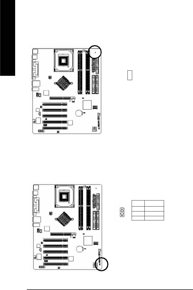
7) RAM_LED
Do not remove memory modules while RAM LED is on. It might cause short or other unexpected
damages due to the stand by voltage. Remove memory modules only when AC Power cord is disconnected.
English
+
-
8) PWR_LED
PWR_LED is connect with the system power indicator to indicate whether the system is on/off. It will blink
when the system enters suspend mode. If you use dual color LED, power LED will turn to another color.
Pin No. Definition
1 MPD+
2 MPD-
1
3 MPD-
- 24 -GA-8I865PE-L Motherboard
- 25 - Hardware Installation Process
English
9) 2X_DET
When an AGP 2X (3.3V) card is installed the 2X_DET will light up, indicating a nonsupported graphics
card is inserted. Informing users that system might not boot up normally due to AGP 2X (3.3V) is not
supported by the chipset.
-
+
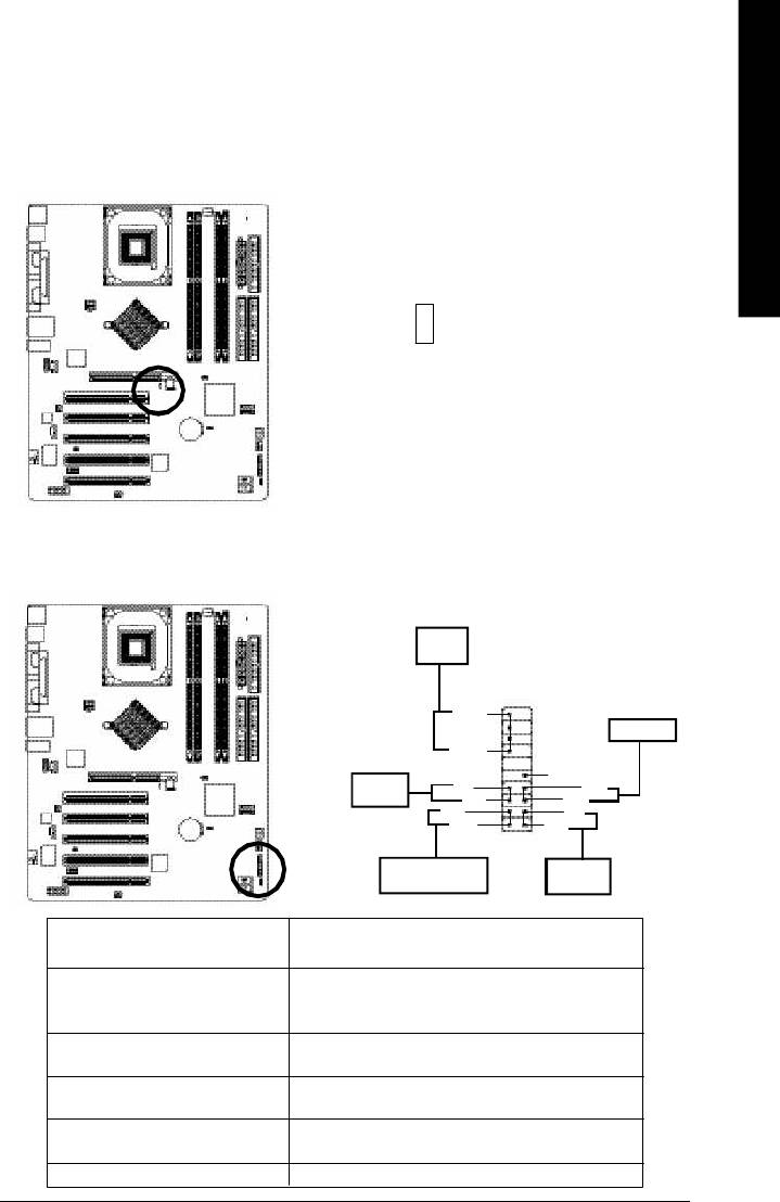
10) F_PANEL (2x10 pins connector)
Please connect the power LED, PC peaker, reset switch and power switch etc of your chassis front panel
to the F_PANEL connector according to the pin assignment above.
Speaker
Connector
20
19
SPEAK-
Reset Switch
SPEAK+
1
NC
Soft Power
PW-
1 RES+
Connector
PW+
1
RES-
MSG-
HD-
1MSG+
1
HD+
2
1
Message LED/Power/
IDE Hard Disk
Sleep LED
Active LED
HD (IDE Hard Disk Active LED) Pin 1: LED anode(+)
(Blue) Pin 2: LED cathode(-)
SPEAK (Speaker Connector) Pin 1: VCC(+)
(Amber) Pin 2- Pin 3: NC
Pin 4: Data(-)
RES (Reset Switch) Open: Normal Operation
(Green) Close: Reset Hardware System
PW (Soft Power Connector) Open: Normal Operation
(Red) Close: Power On/Off
MSG(Message LED/Power/ Pin 1: LED anode(+)
Sleep LED)(Yellow) Pin 2: LED cathode(-)
NC( Purple) NC
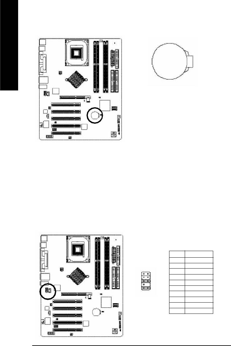
11) BAT (Battery)
English
+
CAUTION
v Danger of explosion if battery is incorrectly
replaced.
v Replace only with the same or equivalent
type recommended by the manufacturer.
v Dispose of used batteries according to the
manufacturer's instructions.
If you want to erase CMOS...
1.Turn OFF the computer and unplug the power cord.
2.Remove the battery, wait for 30 second.
3.Re-install the battery.
4.Plug the power cord and turn ON the computer.
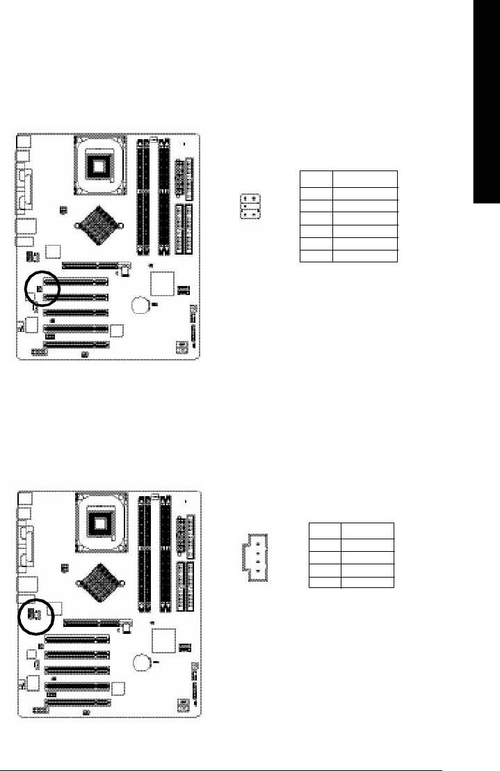
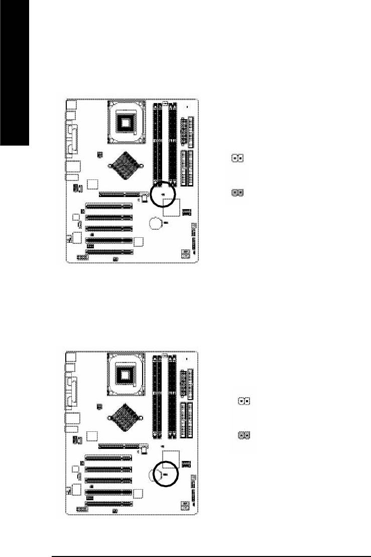
12) F_AUDIO (F_AUDIO Connector)
If you want to use Front Audio connector, you must remove 5-6, 9-10 Jumper. In order to utilize the
front audio header, your chassis must have front audio connector. Also please make sure the pin
assigment on the cable is the same as the pin assigment on the MB header. To find out if the chassis
you are buying support front audio connector, please contact your dealer.Please note, you can have the
alternative of using front audio connector or of using rear audio connector to play sound.
Pin No. Definition
1 MIC
2 GND
3 REF
1 2
4 POWER
5 FrontAudio(R)
109
6 RearAudio(R)
7 Reserved
8 No Pin
9 FrontAudio (L)
10 RearAudio(L)
- 26 -GA-8I865PE-L Motherboard
- 27 - Hardware Installation Process
English
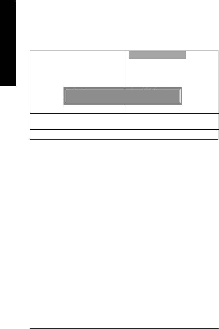
13) SUR_CEN
Please contact your nearest dealer for optional SUR_CEN cable.
Pin No. Definition
1 SUR OUTL
1
2
2 SUR OUTR
5
6
3 GND
4 No Pin
5 CENTER_OUT
6 BASS_OUT
14) CD_IN (CD IN, Black)
Connect CD-ROM or DVD-ROM audio out to the connector.
Pin No. Definition
1 CD-L
1
2 GND
3 GND
4 CD_R
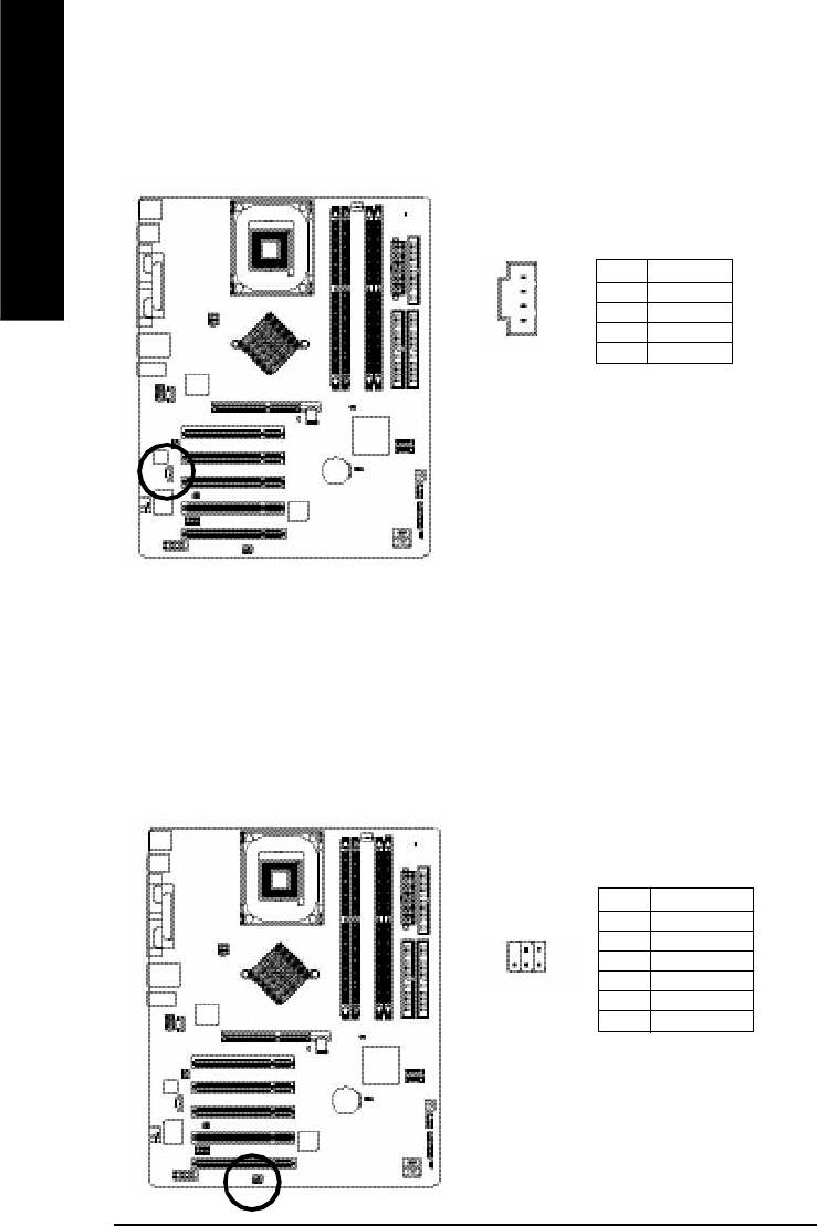
15) AUX_IN (AUX In Connector)
Connect other device(such as PCI TV Tunner audio out)to the connector.
English
Pin No. Definition
1
1 AUX-L
2 GND
3 GND
4 AUX_R
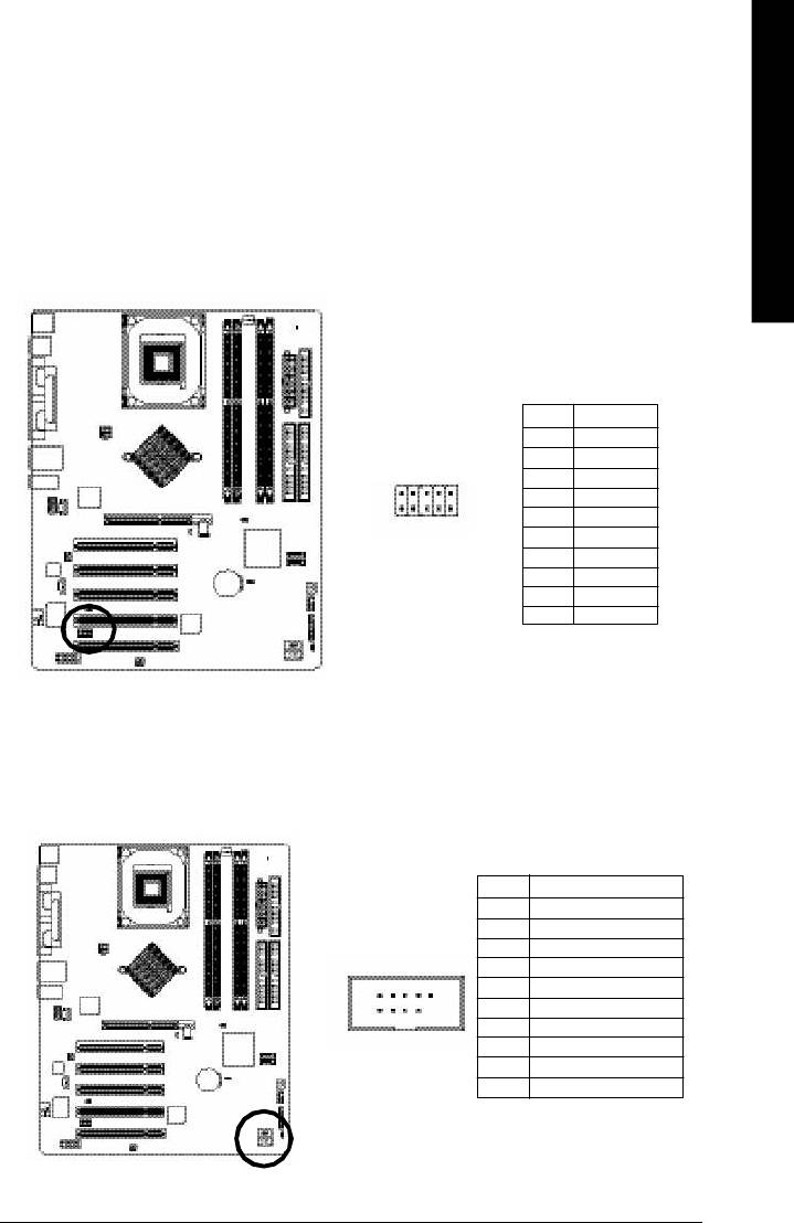
16) SPDIF_IO (SPDIF In/Out)
The SPDIF output is capable of providing digital audio to external speakers or compressed AC3 data to
an external Dolby Digital Decoder. Use this feature only when your stereo system has digital input
function. Use SPDIF IN feature only when your device has digital output function.
Be careful with the polarity of the SPDIF_IO connector. Check the pin assignment carefully while you
connect the SPDIF_IO cable, incorrect connection between the cable and connector will m ake the
device unable to work or even damage it. For optional SPDIF_IO cable, please contact your local
dealer.
Pin No. Definition
1 VCC
62
2 No Pin
3 SPDIF
4 SPDIFI
1
5
5 GND
6 GND
- 28 -GA-8I865PE-L Motherboard
- 29 - Hardware Installation Process
English
17) IR_CIR
Make sure the pin 1 on the IR device is aling with pin one the connector. To enable the IR/CIR function
on the board, you are required to purchase an option IR/CIR m odule. For detail inform ation please
contact your autherized Giga-Byte distributor. To use IR function only, please connect IR module to
Pin1 to Pin5.
Be careful with the polarity of the IR/CIR connector. Check the pin assignment carefully while you
connect the IR/CIR cable, incorrect connection between the cable and connector will make the device
unable to work or even damage it. For optional IR/CIR cable, please contact your local dealer.
Pin No. Definition
1 VCC
2 NC
6
10
3 IRRX
4 GND
5 IRTX
1
5
6 NC
7 CIRRX
8 VCC
9 CIRTX
10 NC
18) F_ USB1 / F_USB2(Front USB Connector, Yellow )
Be careful with the polarity of the F_USB connector. Check the pin assignment carefully while you
connect the F_USB cable, incorrect connection between the cable and connector will make the device
unable to work or even damage it. For optional F_USB cable, please contact your local dealer.
Pin No. Definition
1 Power
2 Power
3 USB0 DX-/USB6 DX-
2 10
4 USB1 Dy-/USB7 Dy-
5 USB0 DX+/USB6 DX+
6 USB1 Dy+/USB7 Dy+
7 GND
1
9
8 GND
9 No Pin
10 NC
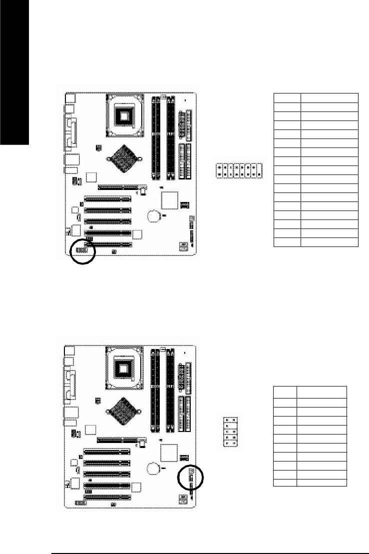
19) GAME (GAME Connector)
This connector supports joystick, MIDI keyboard and other relate audio devices.
English
Pin No. Definition
1 VCC
2 GRX1_R
3 GND
4 GPSA2
5 VCC
6 GPX2_R
2
16
7 GPY2_R
8 MSI_R
9 GPSA1
1 15
10 GND
11 GPY1_R
12 VCC
13 GPSB1
14 MSO_R
15 GPSB2
16 No Pin
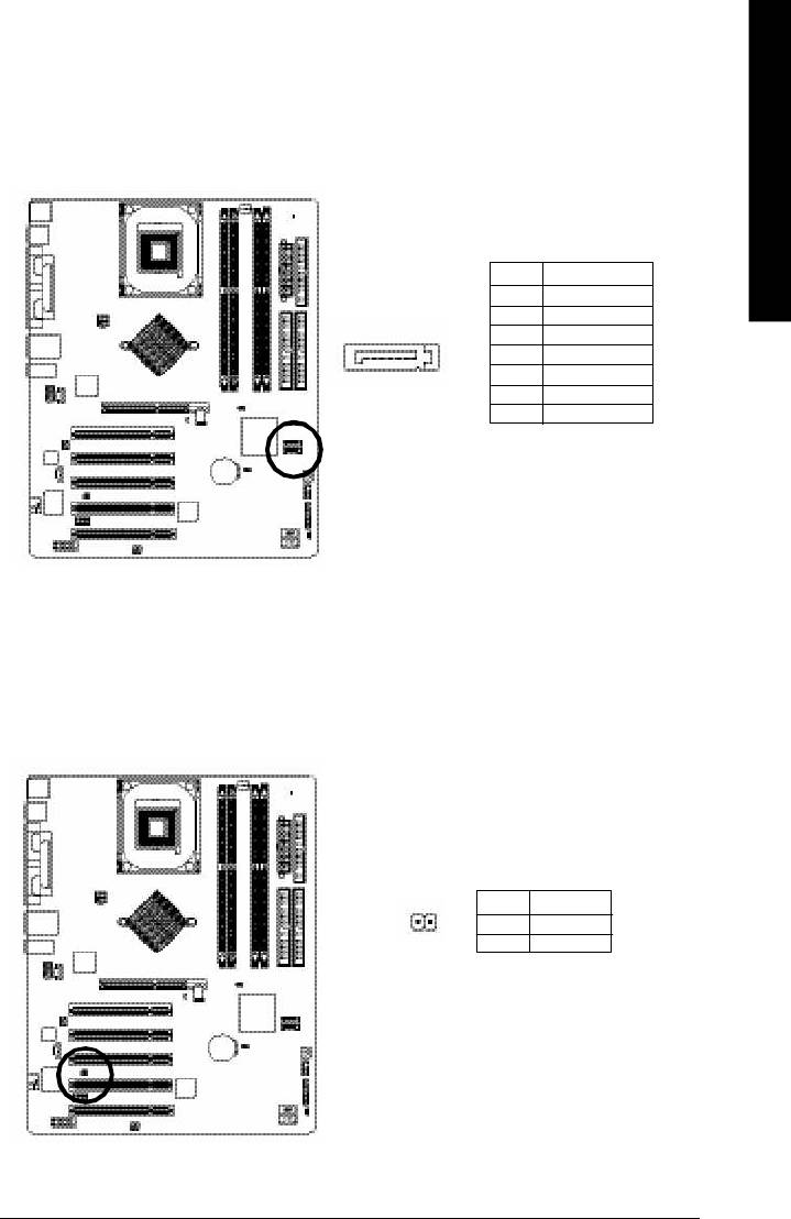
20) INFO_LINK
This connector allows you to connect some external devices to provide you extra function.
Pin No. Definition
1 SMBCLK
2 VCC
10
9
3 SMBDATA
4 GPIO
5 GND
2
1
6 GND
7 No Pin
8 NC
9 +12V
10 +12V
- 30 -GA-8I865PE-L Motherboard
- 31 - Hardware Installation Process
English
21) SATA0/SATA1 (Serial ATA Connector)
You can connect the Serial ATA device to this connector, it provides you high speed transfer rates
(150MB/sec).
Pin No. Definition
1 GND
2 TXP
7
3 TXN
1
4 GND
5 RXN
6 RXP
7 GND
22) CI (CASE OPEN)
This 2 pin connector allows your system to enable or disable the "case open" item in BIOS if the
system case begin remove.
Pin No. Definition
1
1 Signal
2 GND
23) CLR_PWD
When Jumper is set to "open" and system is restarted, the password that is set will be cleared. On the
contrary when Jumper is set to "close", the current status remains.
English
1
open: Clear password
1
close: Normal
24) CLR_CMOS (Clear CMOS)
You may clear the CMOS data to its default values by this jumper. To clear CMOS, temporarily
shor 1-2 pin. Default doesn't include the "Shunter" to prevent from improper use this jumper.
1
Open: Normal
1
Close: Clear CMOS
- 32 -GA-8I865PE-L Motherboard

- 33 - Hardware Installation Process
English

English
- 34 -GA-8I865PE-L Motherboard

English
Chapter 3 BIOS Setup
BIOS Setup is an overview of the BIOS Setup Program. The program that allows users to modify the
basic system configuration. This type of information is stored in battery-backed CMOS RAM so that it
retains the Setup information when the power is turned off.
ENTERING
SETUP
Powering ON the computer and pressing <Del> immediately will allow you to enter Setup. If you require
more advanced BIOS settings, please go to "Advanced BIOS" setting menu.To enter Advanced BIOS
setting menu, press "Ctrl+F1" key on the BIOS screen.
CONTROL
KEYS
<á> Move to previous item
<â> Move to next item
<ß> Move to the item in the left hand
<à> Move to the item in the right hand
Enter Select item
<Esc> Main Menu - Quit and not save changes into CMOS Status Page Setup Menu and
Option Page Setup Menu - Exit current page and return to Main Menu
<+/PgUp> Increase the numeric value or make changes
<-/PgDn> Decrease the numeric value or make changes
<F1> General help, only for Status Page Setup Menu and Option Page Setup Menu
<F2> Item Help
<F3> Reserved
<F4> Reserved
<F5> Restore the previous CMOS value from CMOS, only for Option Page Setup Menu
<F6> Load the file-safe default CMOS value from BIOS default table
<F7> Load the Optimized Defaults
<F8> Q-Flash function
<F9> System Information
<F10> Save all the CMOS changes, only for Main Menu
- 35 - BIOS Setup

GETTING HELP
Main Menu
The on-line description of the highlighted setup function is displayed at the bottom of the screen.
English
Status Page Setup Menu / Option Page Setup Menu
Press F1 to pop up a small help window that describes the appropriate keys to use and the possible
selections for the highlighted item. To exit the Help Window press <Esc>.
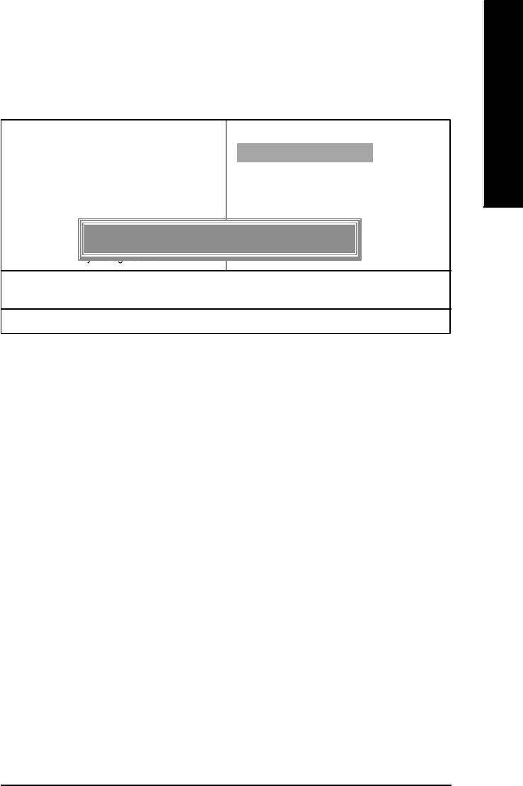
The Main Menu (For example: BIOS Ver.: E2)
Once you enter Award BIOS CMOS Setup Utility, the Main Menu (Figure 1) will appear on the screen.
The Main Menu allows you to select from eight setup functions and two exit choices. Use arrow keys to
select among the items and press <Enter> to accept or enter the sub-menu.
CMOS Setup Utility-Copyright (C) 1984-2003 Award Software
}Standard CMOS Features Load Fail-Safe Defaults
}Advanced BIOS Features Load Optimized Defaults
}Integrated Peripherals Set Supervisor Passw ord
}Power Management Setup Set User Password
}PnP/PCI Configurations Save & Exit Setup
}PC Health Status Exit Without Saving
}Frequency/Voltage Control
ESC:Quit higf:Select Item
F8: Q-Flash F10:Save & Exit Setup
Time, Date, Hard Disk Type...
Figure 1: Main Menu
If you can't find the setting you want, please press "Ctrl+F1" to
search the advanced option widden.
l Standard CMOS Features
This setup page includes all the items in standard compatible BIOS.
l Advanced BIOS Features
This setup page includes all the items of Award special enhanced features.
- 36 -GA-8I865PE-L Motherboard

English
l Integrated Peripherals
This setup page includes all onboard peripherals.
l Power Management Setup
This setup page includes all the items of Green function features.
l PnP/PCI Configurations
This setup page includes all the configurations of PCI & PnP ISA resources.
l PC Health Status
This setup page is the System auto detect Temperature, voltage, fan, speed.
l Frequency/Voltage Control
This setup page is control CPU's clock and frequency ratio.
l Load Fail-Safe Defaults
Fail-Safe Defaults indicates the value of the system parameters which the system would
be in safe configuration.
l Load Optimized Defaults
Optimized Defaults indicates the value of the system parameters which the system would
be in best performance configuration.
l Set Supervisor password
Change, set, or disable password. It allows you to limit access to the system and Setup,
or just to Setup.
l Set User password
Change, set, or disable password. It allows you to limit access to the system.
l Save & Exit Setup
Save CMOS value settings to CMOS and exit setup.
l Exit Without Saving
Abandon all CMOS value changes and exit setup.
- 37 - BIOS Setup

Standard CMOS Features
CMOS Setup Utility-Copyright (C) 1984-2003 Award Software
Standard CMOS Features
English
Date (mm:dd:yy) Tue, Aug 13 2002 Item Help
Time (hh:mm:ss) 22:31:24 Menu Level u
Change the day, month,
}IDE Channel 0 Master [None] year
}IDE Channel 0 Slave [None]
}IDE Channel 1 Master [None] <Week>
}IDE Channel 1 Slave [None] Sun. to Sat.
Drive A [1.44M, 3.5 in.] <Month>
Drive B [None] Jan. to Dec.
Floppy 3 Mode Support [Disabled]
<Day>
Halt On [All, But Keyboard] 1 to 31 (or maximum
allowed in the month)
Base Memory 640K
Extended Memory 130048K <Year>
Total Memory 131072K 1999 to 2098
higf: Move Enter:Select +/-/PU/PD:Value F10:Save ESC:Exit F1:General Help
F5:Previous Values F6:Fail-Safe Defaults F7:Optimized Defaults
Figure 2: Standard CMOS Features
Date
The date format is <week>, <month>, <day>, <year>.
Week The week, from Sun to Sat, determined by the BIOS and is display only
Month The month, Jan. Through Dec.
Day The day, from 1 to 31 (or the maximum allowed in the month)
Year The year, from 1999 through 2098
- 38 -GA-8I865PE-L Motherboard

English
Time
The times format in <hour> <minute> <second>. The time is calculated base on the 24-hour military-
time clock. For example, 1 p.m. is 13:00:00.
IDE Channel 0 Master, Slave / IDE Channel 1 Master, Slave
The category identifies the types of hard disk from drive C to F that has been installed in the computer.
There are two types: auto type, and manual type. Manual type is user-definable; Auto type which will
automatically detect HDD type.
Note that the specifications of your drive must match with the drive table. The hard disk will not work
properly if you enter improper information for this category.
If y ou select User Type, related information will be asked to enter to the following items. Enter the
information directly from the keyboard and press <Enter>. Such information should be provided in the
documentation form your hard disk vendor or the system manufacturer.
CYLS. Number of cylinders
HEADS Number of heads
PRECOMP Write precomp
LANDZONE Landing zone
SECTORS Number of sectors
If a hard disk has not been installed select NONE and press <Enter>.
Drive A / Drive B
The category identifies the types of floppy disk driv e A or drive B that has been installed in the
computer.
None No floppy drive installed
360K, 5.25 in. 5.25 inch PC-type standard drive; 360K byte capacity.
1.2M, 5.25 in. 5.25 inch AT-type high-density drive; 1.2M byte capacity
(3.5 inch when 3 Mode is Enabled).
720K, 3.5 in. 3.5 inch double-sided drive; 720K byte capacity
1.44M, 3.5 in. 3.5 inch double-sided drive; 1.44M byte capacity.
2.88M, 3.5 in. 3.5 inch double-sided drive; 2.88M byte capacity.
- 39 - BIOS Setup

Floppy 3 Mode Support (for Japan Area)
Disabled Normal Floppy Driv e. (Default value)
Drive A Drive A is 3 mode Floppy Drive.
English
Drive B Drive B is 3 mode Floppy Drive.
Both Drive A & B are 3 mode Floppy Drives.
Halt on
The category determines whether the computer will stop if an error is detected during power up.
NO Errors The system boot will not stop for any error that may be detected
and you will be prompted.
All Errors Whenever the BIOS detects a non-fatal error the system will be stopped.
All, But Keyboard The system boot will not stop for a keyboard error; it will stop for
all other errors. (Default value)
All, But Diskette The system boot will not stop for a disk error; it will stop for all
other errors.
All, But Disk/Key The system boot will not stop for a keyboard or disk error; it will
stop for all other errors.
Memory
The category is display-only which is determined by POST (Power On Self Test) of the BIOS.
Base Memory
The POST of the BIOS will determine the amount of base (or conventional) memory
installed in the system.
The value of the base memory is typically 512 K for systems with 512 K memory
installed on the motherboard, or 640 K for systems with 640 K or more memory
installed on the motherboard.
Extended Memory
The BIOS determines how much extended memory is present during the POST.
This is the amount of memory located above 1 MB in the CPU's memory
address map.
- 40 -GA-8I865PE-L Motherboard

English
Advanced BIOS Features
CMOS Setup Utility-Copyright (C) 1984-2003 Award Software
Advanced BIOS Features
u Hard Disk Boot Priority [Press Enter] Item Help
First Boot Device [Floppy] Menu Level u
Second Boot Device [Hard Disk]
Third Boot Device [CDROM]
Password Check [Setup]
# CPU Hyper-Threading [Enabled]
higf: Move Enter:Select +/-/PU/PD:Value F10:Save ESC:Exit F1:General Help
F5:Previous Values F6:Fail-Safe Defaults F7:Optimized Defaults
Figure 3: Advanced BIOS Features
®
®
" # " System will detect automatically and show up when you install the Intel
Pentium
4 processor
with HT Technology.
Hard Disk Boot Priority
Press Enter Select Hard Disk Boot Device priority.
First / Second / Third Boot Device
M This feature allows you to select the boot device priority.
Floppy Select your boot device priority by Floppy.
LS120 Select your boot device priority by LS120.
Hard Disk Select your boot device priority by Hard Disk.
CDROM Select your boot device priority by CDROM.
ZIP Select your boot device priority by ZIP.
USB-FDD Select your boot device priority by USB-FDD.
USB-ZIP Select your boot device priority by USB-ZIP.
- 41 - BIOS Setup

USB-CDROM Select your boot device priority by USB-CDROM.
USB-HDD Select your boot device priority by USB-HDD.
LAN Select your boot dev ice priority by LAN.
Disabled Select your boot device priority by Disabled.
English
Password Check
System The system will not boot and will not access to Setup page if the correct
password is not entered at the prompt.
Setup The system will boot but will not access to Setup page if the correct password
is not entered at the prompt. (Default v alue)
CPU Hyper-Threading
Enabled Enables CPU Hyper Threading Feature. Please note that this feature is only
working for operating system with multi processors mode supported.
(Default value)
Disabled Disables CPU Hyper Threading.
- 42 -GA-8I865PE-L Motherboard

English
Integrated Peripherals
CMOS Setup Utility-Copyright (C) 1984-2003 Award Software
Integrated Peripherals
On-Chip Primary PCI IDE [Enabled] Item Help
On-Chip Secondary PCI IDE [Enabled] Menu Level u
On-Chip SATA [Auto] If a hard disk
x SATA Port0 Configure as [SATA Port0] controller card is
SATA Port1 Configure as SATA Port1 used, set at Disabled
USB Controller [Enabled]
USB 2.0 Controller [Enabled] [Enabled]
USB Keyboard Support [Disabled] Enable on-chip IDE
USB Mouse Support [Disabled] PORT
AC97 Audio [Auto]
Onboard H/W LAN [Enabled] [Disabled]
Onboard Serial Port 1 [3F8/IRQ4] Disable on-chip IDE
Onboard Serial Port 2 [2F8/IRQ3] PORT
UART Mode Select [Normal]
x UR2 Duplex Mode Half
Onboard Parallel Port [378/IRQ7]
Parallel Port Mode [SPP]
x ECP Mode Use DMA 3
Game Port Address [201]
Midi Port Address [330]
Midi Port IRQ [10]
CIR Port Address [Disabled]
x CIR Port IRQ 11
higf: Move Enter:Select +/-/PU/PD:Value F10:Save ESC:Exit F1:General Help
F5:Previous Values F6:Fail-Safe Defaults F7:Optimized Defaults
Figure 4: Integrated Peripherals
- 43 - BIOS Setup

On-Chip Primary PCI IDE
Enabled Enable onboard 1st channel IDE port. (Default value)
Disabled Disable onboard 1st channel IDE port.
English
On-Chip Secondary PCI IDE
Enabled Enable onboard 2nd channel IDE port. (Default value)
Disabled Disable onboard 2nd channel IDE port.
On-chip SATA
Disabled Disable SATA controller.
Auto When no device is plugged in IDE1 or IDE2, SATA controller will remap to IDE
controller. (Default Value)
Manual Set SATA Mode manually.
SATA Port0 Configure as
IDE Pri. Master Remap SATA Port 0 to IDE Pri. Master.
IDE Pri. Slave Remap SATA Port 0 to IDE Pri. Slave.
IDE Sec. Master Remap SATA Port 0 to IDE Sec. Master.
IDE Sec. Slave Remap SATA Port 0 to IDE Sec. Slave.
SATA Port0 SATA controller set to SATA port0. As this mode, it support by WinXP or
later OS only. (Default value)
SATA Port1 SATA controller set to SATA port1. As this mode, it support by WinXP or
later OS only .
SATA Port1 Configure as
The values depend on SATA Port0.
USB Controller
Enabled Enable USB Controller. (Default value)
Disabled Disable USB Controller.
- 44 -GA-8I865PE-L Motherboard

English
USB 2.0 Controller
Disable this function if you are not using onboard U SB 2.0 feature.
Enabled Enable USB 2.0 Controller. (Default v alue)
Disabled Disable USB 2.0 Controller.
USB Keyboard Support
Enabled Enable USB Keyboard Support.
Disabled Disable USB Keyboard Support. (Default value)
USB Mouse Support
Enabled Enable USB Mouse Support.
Disabled Disable USB Mouse Support. (Default v alue)
AC97 Audio
Auto Enable onboard AC'97 audio function. (Default Value)
Disabled Disable this function.
Onboard H/W LAN
Enabled Enable Onboard H/W LAN function. (Default value)
Disabled Disable this function.
Onboard Serial Port 1
Auto BIOS will automatically setup the port 1 address.
3F8/IRQ4 Enable onboard Serial port 1 and address is 3F8. (Default value)
2F8/IRQ3 Enable onboard Serial port 1 and address is 2F8.
3E8/IRQ4 Enable onboard Serial port 1 and address is 3E8.
2E8/IRQ3 Enable onboard Serial port 1 and address is 2E8.
Disabled Disable onboard Serial port 1.
- 45 - BIOS Setup

Onboard Serial Port 2
Auto BIOS will automatically setup the port 2 address.
3F8/IRQ4 Enable onboard Serial port 2 and address is 3F8.
English
2F8/IRQ3 Enable onboard Serial port 2 and address is 2F8. (Default value)
3E8/IRQ4 Enable onboard Serial port 2 and address is 3E8.
2E8/IRQ3 Enable onboard Serial port 2 and address is 2E8.
Disabled Disable onboard Serial port 2.
UART Mode Select
(This item allows you to determine which Infra Red(IR) function of Onboard I/O chip)
ASKIR Set onboard I/O chip UART to ASKIR Mode.
IrDA Set onboard I/O chip UART to IrDA Mode.
Normal Set onboard I/O chip UART to Normal Mode. (Default Value)
UR2 Duplex Mode
Half IR Function Duplex Half. (Default Value)
Full IR Function Duplex Full.
Onboard Parallel port
378/IRQ7 Enable onboard LPT port and address is 378/IRQ7. (Default Value)
278/IRQ5 Enable onboard LPT port and address is 278/IRQ5.
Disabled Disable onboard LPT port.
3BC/IRQ7 Enable onboard LPT port and address is 3BC/IRQ7.
Parallel Port Mode
SPP Using Parallel port as Standard Parallel Port. (Default Value)
EPP Using Parallel port as Enhanced Parallel Port.
ECP Using Parallel port as Extended Capabilities Port.
ECP+EPP Using Parallel port as ECP & EPP mode.
ECP Mode Use DMA
3 Set ECP Mode Use DMA to 3. (Default Value)
1 Set ECP Mode Use DMA to 1.
- 46 -GA-8I865PE-L Motherboard

English
Game Port Address
201 Set Game Port Address to 201. (Default Value)
209 Set Game Port Address to 209.
Disabled Disable this function.
Midi Port Address
300 Set Midi Port Address to 300.
330 Set Midi Port Address to 330.(Default Value)
Disabled Disable this function.
Midi Port IRQ
5 Set Midi Port IRQ to 5.
10 Set Midi Port IRQ to 10. (Default Value)
CIR Port Address
310 Set CIR Port Address to 310.
320 Set CIR Port Address to 320.
Disabled Disable this function. (Default Value)
CIR Port IRQ
5 Set CIR Port IRQ to 5.
111 Set CIR Port IRQ to 11. (Default Value)
- 47 - BIOS Setup

Power Management Setup
CMOS Setup Utility-Copyright (C) 1984-2003 Award Software
Power Management Setup
English
ACPI Suspend Type [S1(POS)] Item Help
Power LED in S1 State [Blinking] Menu Level u
Off by Power button [Instant-Off] [S1]
PME Event Wake Up [Enabled] Set suspend type to
ModemRingOn/WakeOnLan [Enabled] Power On Suspend under
Resume by Alarm [Disabled] ACPI OS
x Date (of Month) Alarm Everyday
x Time (hh:mm:ss) 0 0 0 [S3]
Power On By Mouse [Disabled] Set suspend ty pe to
Power On By Keyboard [Disabled] Suspend to RAM under
x KB Power ON Password Enter ACPI OS
AC BACK Function [Soft-Off]
higf: Move Enter:Select +/-/PU/PD:Value F10:Save ESC:Exit F1:General Help
F5:Previous Values F6:Fail-Safe Defaults F7:Optimized Defaults
Figure 5: Power Management Setup
ACPI Suspend Type
S1(POS) Set ACPI suspend type to S1. (Default Value)
S3(STR) Set ACPI suspend type to S3.
Power LED in S1 state
Blinking In standby mode(S1), power LED will blink. (Default Value)
Dual/OFF In standby mode(S1):
a. If use single color LED, power LED will turn off.
b. If use dual color LED, power LED will turn to another color.
Off by Power button
Instant-off Press power button then Power off instantly. (Default value)
Delay 4 Sec. Press power button 4 sec to Power off. Enter suspend if button is pressed less
than 4 sec.
- 48 -GA-8I865PE-L Motherboard

English
PME Event Wake Up
Disabled Disable this function.
Enabled Enable PME Event Wake up. (Default Value)
ModemRingOn/WakeOnLAN
Disabled Disable Modem Ring on/wake on Lan function.
Enabled Enable Modem Ring on/wake on Lan. (Default Value)
Resume by Alarm
You can set "Resume by Alarm" item to enabled and key in Data/time to power on system.
Disabled Disable this function. (Default Value)
Enabled Enable alarm function to POWER ON system.
If RTC Alarm Lead To Power On is Enabled.
Date ( of Month) Alarm : Everyday, 1~31
Time ( hh: mm: ss) Alarm : (0~23) : (0~59) : (0~59)
Power On By Mouse
Disabled Disabled this function. (Default value)
Mouse Click Double click on PS/2 mouse left button to power on system.
Power On By Keyboard
Password Enter from 1 to 5 characters to set the Keyboard Power On Password.
Disabled Disabled this function. (Default value)
Keyboard 98 If your keyboard have "POWER Key " button, you can press the key to
power on your system.
KB Power ON Password
Enter Input password (from 1 to 5 characters) and press Enter to set the Key-
board Power On Password.
AC BACK Function
Memory System power on depends on the status before AC lost.
Soft-Off Always in Off state when AC back. (Default value)
Full-On Always power on the system when AC back.
- 49 - BIOS Setup

PnP/PCI Configurations
CMOS Setup Utility-Copyright (C) 1984-2003 Award Software
PnP/PCI Configurations
English
PCI 1/PCI 5 IRQ Assignment [Auto] Item Help
PCI 2 IRQ Assignment [Auto] Menu Level u
PCI 3 IRQ Assignment [Auto]
PCI 4 IRQ Assignment [Auto]
higf: Move Enter:Select +/-/PU/PD:Value F10:Save ESC:Exit F1:General Help
F5:Previous Values F6:Fail-Safe Defaults F7:Optimized Defaults
Figure 6: PnP/PCI Configurations
PCI 1/PCI 5 IRQ Assignment
Auto Auto assign IRQ to PCI 1/PCI 5. (Default v alue)
3,4,5,7,9,10,11,12,14,15 Set IRQ 3,4,5,7,9,10,11,12,14,15 to PCI 1/PCI 5.
PCI 2 IRQ Assignment
Auto Auto assign IRQ to PCI 2. (Default value)
3,4,5,7,9,10,11,12,14,15 Set IRQ 3,4,5,7,9,10,11,12,14,15 to PCI 2.
PCI 3 IRQ Assignment
Auto Auto assign IRQ to PCI 3. (Default value)
3,4,5,7,9,10,11,12,14,15 Set IRQ 3,4,5,7,9,10,11,12,14,15 to PCI 3.
PCI 4 IRQ Assignment
Auto Auto assign IRQ to PCI 4. (Default value)
3,4,5,7,9,10,11,12,14,15 Set IRQ 3,4,5,7,9,10,11,12,14,15 to PCI 4.
- 50 -GA-8I865PE-L Motherboard

English
PC Health Status
CMOS Setup Utility-Copyright (C) 1984-2003 Award Software
PC Health Status
Reset Case Open Status [Disabled] Item Help
Case Opened No Menu Level u
Vcore OK [Disabled]
DDR25V OK Don't reset case
+3.3V OK open status
+5V OK
+12V OK [Enabled]
Current CPU Temperature 40°C Clear case open
Current CPU FAN Speed 6490 RPM status at next boot
Current SYSTEM FAN Speed 0 RPM
CPU Warning Temperature [Disabled]
CPU FAN Fail Warning [Disabled]
SYSTEM FAN Fail Warning [Disabled]
higf: Move Enter:Select +/-/PU/PD:Value F10:Save ESC:Exit F1:General Help
F5:Previous Values F6:Fail-Safe Defaults F7:Optimized Defaults
Figure 7: PC Health Status
Reset Case Open Status
Case Opened
If the case is closed, "Case O pened" will show "No".
If the case hav e been ope ned, "Case Opened" w ill show "Yes".
If you want to reset "Case Opene d" value, set "Reset Case Open Status" to
"Enabled" and save CMOS, your computer will restart.
Current Voltage (V) Vcore / DDR25V / +3.3V / +5V / +12V
Detect system's voltage status automatically.
- 51 - BIOS Setup

Current CPU Temperaturee
Detect CPU Temp. automatically..
English
Current CPU/SYSTEM FAN Speed (RPM)
Detect CPU/SYSTEM Fan speed status automatically.
CPU Warning Temperature
60°C / 140°F Monitor CPU Temp. at 60°C / 140°F.
70°C / 158°F Monitor CPU Temp. at 70°C / 158°F.
80°C / 176°F Monitor CPU Temp. at 80°C / 176°F.
90°C / 194°F Monitor CPU Temp. at 90°C / 194°F.
8Disabled Disable this function.(Default v alue)
CPU FAN Fail Warning
Disabled Fan Warning Function Disable. (Default value)
Enabled Fan Warning Function Enable.
SYSTEM FAN Fail Warning
Disabled Fan Warning Function Disable. (Default value)
Enabled Fan Warning Function Enable.
- 52 -GA-8I865PE-L Motherboard

English
Frequency/Voltage Control
CMOS Setup Utility-Copyright (C) 1984-2003 Award Software
Frequency/Voltage Control
CPU Clock Ratio [15X] Item Help
CPU Host Clock Control [Disabled] Menu Level u
øCPU Host Frequency (Mhz) 100
øAGP/PCI/SRC Fixed 66/33/100
Memory Frequency For [Auto]
Memory Frequency (Mhz) 266
AGP/PCI/SRC Frequency (Mhz) 66/33/100
DIMM OverVoltage Control [Normal]
AGP OverVoltage Control [Normal]
CPU Voltage Control [Normal]
Normal CPU Vcore 1.4750V
higf: Move Enter:Select +/-/PU/PD:Value F10:Save ESC:Exit F1:General Help
F5:Previous Values F6:Fail-Safe Defaults F7:Optimized Defaults
Figure 8: Frequency/Voltage Control
øThose items will be available when "CPU Host Clock Control" is set to Enabled.
CPU Clock Ratio
This option will not be shown or not be available if you are using a CPU with the locked ratio.
15X~21X It depends on CPU Clock Ratio.
This setup option will automatically assign by CPU detection.
For C-Stepping P4: 8X,10X~24X default: 15X
For Northwood CPU: 12X~24X default: 16X
The option w ill display "Locked" and read only if the CPU ratio is not changeable.
- 53 - BIOS Setup

CPU Host Clock Control
Note: If system hangs up before enter CMOS setup utility, wait for 20 sec for times out reboot. When
time out occur, system will reset and run at CPU default Host clock at nex t boot.
English
Disabled Disable CPU Host Clock Control.(Default value)
Enabled Enable CPU Host Clock Control.
CPU Host Frequency
100MHz ~ 355MHz Set CPU Host Clock from 100MHz to 355MHz.
Incorrect using it may cause your system broken. For power End-User use only!
AGP/PCI/SRC Fixed
Serial ATA device is very sensitiv e to SRC clock. SRC over clock may make Serial ATA device
function can't work properly.
Adjust AGP/PCI/SRC clock asychrohous with CPU.
Memory Frequency For
for FSB(Front Side Bus) frequency=400MHz,
2.66 Memory Frequency = Host clock X 2.66.
Auto Set Memory frequency by DRAM SPD data. (Default value)
for FSB(Front Side Bus) frequency=533MHz,
2.0 Memory Frequency = Host clock X 2.0.
2.5 Memory Frequency = Host clock X 2.5.
Auto Set Memory frequency by DRAM SPD data. (Default value)
for FSB(Front Side Bus) frequency=800MHz,
2.0 Memory Frequency = Host clock X 2.0.
1.6 Memory Frequency = Host clock X 1.5.
1.33 Memory Frequency = Host clock X 1.33.
Auto Set Memory frequency by DRAM SPD data. (Default value)
Memory Frequency(Mhz)
The values depend on CPU Host Frequency(Mhz) .
- 54 -GA-8I865PE-L Motherboard

English
AGP/PCI/SRC Frequency(Mhz)
The values depend on Fixed AGP/PCI/SRC Frequency.
DIMM OverVoltage Control
Normal Set DIMM OverVoltage Control to Normal. (Default value)
+0.1V Set DIMM OverVoltage Control to +0.1V.
+0.2V Set DIMM OverVoltage Control to +0.2V.
+0.3V Set DIMM OverVoltage Control to +0.3V.
AGP OverVoltage Control
Normal Set AGP OverVoltage Control to Normal. (Default value)
+0.1V Set AGP OverVoltage Control to +0.1V.
+0.2V Set AGP OverVoltage Control to +0.2V.
+0.3V Set AGP OverVoltage Control to +0.3V.
CPU Voltage Control
Supports adjustable CPU Vcore from 0.8375V to 1.7600V.
(Default value: Normal)
Normal CPU Vcore
Display y our CPU Vcore Voltage.
- 55 - BIOS Setup
Load Fail-Safe Defaults
CMOS Setup Utility-Copyright (C) 1984-2003 Award Software
}Standard CMOS Features Load Fail-Safe Defaults
English
}Advanced BIOS Features Load Optimized Defaults
}Integrated Peripherals Set Supervisor Passw ord
}Power Management Setup Set User Password
}PnP/PCI Configurations Save & Exit Setup
Load Fail-Safe Defaults? (Y/N)?Y
}PC Health Status Exit Without Saving
}Frequency/Voltage Control
ESC:Quit higf:Select Item
F8: Q-Flash F10:Save & Exit Setup
Load Fail-Safe Defaults
Figure 9: Load Fail-Safe Defaults
Load Fail-Safe Defaults
Fail-Safe defaults contain the most appropriate values of the system parameters that allow
minimum system performance.
- 56 -GA-8I865PE-L Motherboard
English
Load Optimized Defaults
CMOS Setup Utility-Copyright (C) 1984-2003 Award Software
}Standard CMOS Features Load Fail-Safe Defaults
}Advanced BIOS Features Load Optimized Defaults
}Integrated Peripherals Set Supervisor Passw ord
}Power Management Setup Set User Password
}PnP/PCI Configurations Save & Exit Setup
}PC Health Status Exit Without Saving
Load Optimized Defaults? (Y/N)?Y
}Frequency/Voltage Control
ESC:Quit higf:Select Item
F8: Q-Flash F10:Save & Exit Setup
Load Optimized Defaults
Figure 10: Load Optimized Defaults
Load Optimized Defaults
Selecting this field loads the factory defaults for BIOS and Chipset Features which the
system automatically detects.
- 57 - BIOS Setup

Set Supervisor/User Password
CMOS Setup Utility-Copyright (C) 1984-2003 Award Software
}Standard CMOS Features Load Fail-Safe Defaults
English
}Advanced BIOS Features Load Optimized Defaults
}Integrated Peripherals Set Supervisor Passw ord
}Power Management Setup Set User Password
}PnP/PCI Configurations Save & Exit Setup
Enter Password:
}PC Health Status Exit Without Saving
}Frequency/Voltage Control
ESC:Quit higf:Select Item
F8: Q-Flash F10:Save & Exit Setup
Change/Set/Disable Password
Figure 11: Password Setting
When you select this function, the following message will appear at the center of the screen to assist
you in creating a password.
Type the password, up to eight characters, and press <Enter>. You will be asked to confirm the
password. Type the password again and press <Enter>. You may also press <Esc> to abort the
selection and not enter a password.
To disable password, just press <Enter> when you are prompted to enter password. A message
"PASSWORD DISABLED" will appear to confirm the password being disabled. Once the password is
disabled, the system will boot and you can enter Setup freely.
The BIOS Setup program allows you to specify two separate passwords:
SUPERVISOR PASSWORD and a USER PASSWORD. When disabled, anyone may access
all BIOS Setup program function. When enabled, the Supervisor password is required for entering the
BIOS Setup program and having full configuration fields, the User password is required to access only
basic items.
If y ou select "System" at "Passw ord C heck" in Advance BIOS Features Menu, you will be
prompted for the password every time the system is rebooted or any time you try to enter Setup Menu.
If you select "Setup" at "Password Check" in Advance BIOS Features Menu, you will be prompted
only when you try to enter Setup.
- 58 -GA-8I865PE-L Motherboard

English
Save & Exit Setup
CMOS Setup Utility-Copyright (C) 1984-2003 Award Software
}Standard CMOS Features Load Fail-Safe Defaults
}Advanced BIOS Features Load Optimized Defaults
}Integrated Peripherals Set Supervisor Passw ord
}Power Management Setup Set User Password
}PnP/PCI Configurations Save & Exit Setup
Save to CMOS and EXIT (Y/N)? Y
}PC Health Status Exit Without Saving
}Frequency/Voltage Control
ESC:Quit higf:Select Item
F8: Q-Flash F10:Save & Exit Setup
Save Data to CMOS
Figure 12: Save & Exit Setup
Type "Y" will quit the Setup Utility and save the user setup value to RTC CMOS.
Type "N" will return to Setup Utility.
- 59 - BIOS Setup

Exit Without Saving
CMOS Setup Utility-Copyright (C) 1984-2003 Award Software
}Standard CMOS Features Load Fail-Safe Defaults
English
}Advanced BIOS Features Load Optimized Defaults
}Integrated Peripherals Set Supervisor Passw ord
}Power Management Setup Set User Password
}PnP/PCI Configurations Save & Exit Setup
Quit Without Saving (Y/N)? N
}PC Health Status Exit Without Saving
}Frequency/Voltage Control
ESC:Quit higf:Select Item
F8: Q-Flash F10:Save & Exit Setup
Abandon all Data
Figure 13: Exit Without Saving
Type "Y" will quit the Setup Utility without saving to RTC CMOS.
Type "N" will return to Setup Utility.
- 60 -GA-8I865PE-L Motherboard

English
- 61 - BIOS Setup

English
- 62 -GA-8I865PE-L Motherboard

English
Revision History
Chapter 4 Technical Reference
TM
@ BIOS
Introduction
Gigabyte announces @ BIOS
Windows BIOS live update utility
Have you ever updated BIOS by yourself? Or like
many other people, you just know what BIOS is,
but always hesitate to update it? Because you think
updating newest BIOS is unnecessary and actually
you don't know how to update it.
Maybe not like others, you are very experienced in BIOS updating and spend quite a lot of time
to do it. But of course you don’t like to do it too much. First, download different BIOS from website and
then switch the operating system to DOS mode. Secondly, use different flash utility to update BIOS.
The above process is not a interesting job. Besides, always be carefully to store the BIOS source
code correctly in your disks as if you update the wrong BIOS, it will be a nightmare.
Certainly, you wonder why motherboard vendors could not just do something right to save your
time and effort and save you from the lousy BIOS updating work? Here it comes! Now Gigabyte
announces @BIOS— the first Windows BIOS live update utility. This is a smart BIOS update
software. It could help you to download the BIOS from internetand update it. Not like the other BIOS
update software, it's a Windows utility. With the help of "@BIOS", BIOS updating is no more than a
click.
Besides, no matter which mainboard you are using, if it's a Gigabyte's product*, @BIOS help
you to maintain the BIOS. This utility could detect your correct mainboard model and help you to
choose the BIOS accordingly. It then downloads the BIOS from the nearest Gigabyte ftp site
automatically. There are several different choices; you could use "Internet Update" to download and
update your BIOS directly. Or you may want to keep a backup for your current BIOS, just choose
"Save Current BIOS" to save it first. You make a wise choice to use Gigabyte, and @BIOS update
your BIOS smartly. You are now worry free from updating wrong BIOS, and capable to maintain and
manage your BIOS easily. Again, Gigabyte's innovative product erects a milestone in mainboard
industries.
For such a wonderful software, how much it costs? Impossible! It's free! Now, if you buy a
Gigabyte's motherboard, you could find this amazing software in the attached driver CD. But please
remember, connected to internet at first, then you could have a internet BIOS update from your
Gigabyte @BIOS.
- 63 -
Technical Reference

TM
Easy Tune
4 Introduction
TM
Gigabyte announces EasyTune
4
Windows based Overclocking utility
English
EasyTune 4 carries on the heritage so as to pave the way for future generations.
Overclock" might be one of the most common issues
in computer field. But have many users ever tried it?
The answer is probably "no". Because "Overclock"
is thought to be very difficult and includes a lot of
technical know-how, sometimes "Overclock" is even
considered as special skills found only in some
enthusiasts. But as to the experts in "Overclock",
what's the truth? They may spend quite a lot of time
and money to study, try and use many different hard-
ware or BIOS tools to do "Overclock". And even with these technologies, they still learn that it's quite a
risk because the safety and stability of an "Overclock" system is unknown. Now everything is different
because of a Windows based overclocking utility "EasyTune 4" --announced by Gigabyte. This win-
dows based utility has totally changed the gaming rule of "Overclock". This is the first windows based
overclocking utility is suitable for both normal and power users. Users can choose either "Easy Mode"
or "Advanced Mode" for overclocking at their convenience. For users who choose "Easy Mode", they
just need to click "Auto Optimize" to have autoed and immediate CPU overclocking. This software will
then overdrive CPU speed automatically with the result being shown in the control panel. If users prefer
"Overclock" by them, there is also another choice. Click "Advanced Mode" to enjoy "sport drive" class
Overclocking user interface. "Advanced Mode", allows users to change the system bus / AGP /
Memory working frequency in small increments to get ultimate system performance. It operates in
coordination with Gigabyte motherboards. Besides, it is different from other traditional over-clocking
methods, EasyTune 4 doesn't require users to change neither BIOS nor hardware switch/ jumper setting;
on the other hand, they can do "Overclock" at easy step . Therefore, this is a safer way for "Overclock"
as nothing is changed on software or hardware. If user runs EasyTune 4 over system's limitation, the
biggest lost is only to restart the computer again and the side effect is then well controlled. Moreover, if one
well-performed system speed has been tested in EasyTune 4, user can "Save" this setting and "Load"
it in next time. Obviously, Gigabyte EasyTune 4 has already turned the "Overclock" technology toward
to a newer generation. This wonderful software is now free bundled in Gigabyte motherboard attached in
driver CD. Users may make a test drive of "EasyTune 4" to find out more amazing features by
themselves.
*Some Gigabyte products are not fully supported by EasyTune 4. Please find the products supported list
in the web site.
*Any "Overclocking action" is at user's risk, Gigabyte Technology will not be responsible for any
damage or instability to your processor, motherboard, or any other components.
- 64 -GA-8I865PE-L Motherboard

English
Flash BIOS Method Introduction
Method 1 : Q-Flash
Flash BIOS Method Introduction
™
Q-Flash
is a BIOS flash utility embedded in Flash ROM. With this utility, users only have to stay in
™
the BIOS menu when they want to update BIOS. Q-Flash
allows users to flash BIOS without any
™
utility in DOS or Windows. Using Q-Flash
indicating no more fooling around with any complicated
instructions and operating system since it is in the BIOS menu.
Please note that because updating BIOS has potential risk, please do it with caution!! We
are sorry that Gigabyte Technology Co., Ltd is not responsible for damages of system
because of incorrect manipulation of updating BIOS to avoid any claims from end-users.
Before You Begin:
™
Before you start updating BIOS with the Q-Flash
utility, please follow the steps below first.
1. Download the latest BIOS for your motherboard from Gigabyte's website.
2. Extract the BIOS file downloaded and save the BIOS file (the one with model name.Fxx. For
example, 7VRXP.F12) to a floppy disk.
3. Reboot your PC and press Del to enter BIOS menu.
The BIOS upgrading guides below are separated into two parts.
If your motherboard has dual BIOS, please refer to Part One.
If your motherboard has single BIOS, please refer to Part Two.
- 65 -
Technical Reference

Part One:
™
Updating BIOS with Q-Flash
Utility on Dual BIOS Motherboards.
Some of Gigabyte motherboards are equipped with dual BIOS. In the BIOS menu of the
English
™
™
motherboards supporting Q-Flash
and Dual BIOS, the Q-Flash
utility and Dual BIOS utility are
™
combined in the same screen. This section only deals with how to use Q-Flash
utility.
In the following sections, we take GA-7VRXP as the example to guide you how to flash BIOS from
an older version to the latest version. For example, from F10 to F12.
Ame r ic an Rel e as e :0 8 /2 3/ 200 2
Megatrends AMI BI OS ( C) 19 9 9 A merican Megatrend
7VRXP F10
AMD-Athlon(tm) Pro ce sso r- 133 3MHz
The BIOS file is F10
Check System Heal th !
Checking NVRAM. ..Upd at e OK
before updating
262144KB
DEL:Steup/Dual BIOS/Q-Flash F8:Boot Me nu F1 2:N etw or k b oo t TAB: Logo
Auto-Detecting Pri Master..IDE Hard Disk
Auto-Detecting Pri Slave...Not Detected
Auto-Detecting Sec Master..ATAPI CDROM
Auto-Detecting Sec Slave.. Not Detected
( C ) Amer ica n Meg atr end s Inc .,
62-2003-001199-00101111-040201-KT333-GA7VRXP1-
™
Entering the Q-Flash
utility:
™
Step1: To use Q-Flash
utility, you must press Del in the boot screen to enter BIOS menu.
AMIBIOS SIMPLE SETU P U TILITY - VERSION 2.00
(C ) 2001 American M egatr end s, Inc . All Ri ghts R es erv ed
STAN DARD CM OS SETUP INTEGRATED PERIPHERALS
BIOS FEATURES SETUP HARDWARE MONITOR & MISC SETUP
CHIPSET FEATU RES SETUP SU PERVISOR PASSWORD
POWER MANAGEM EN T SETUP USER PASSWORD
PNP / PC I C ON FIGU RATION IDE HDD AUTO DETEC TION
LOAD FAIL-SAFE DEFAULTS SAVE & EXIT SETU P
LOAD OPTIM IZED DEFA U LTS EXIT WITHOUT SAVIN G
ESC: Quit hifg : S elec t Item F5: Old Values F6: Fail-Safe Values
F7: Opti mize d V alu es F8: Dual BIOS/Q-Flash F10:Sav e & Exit
Load Fail-Safe Defaults
- 66 -GA-8I865PE-L Motherboard
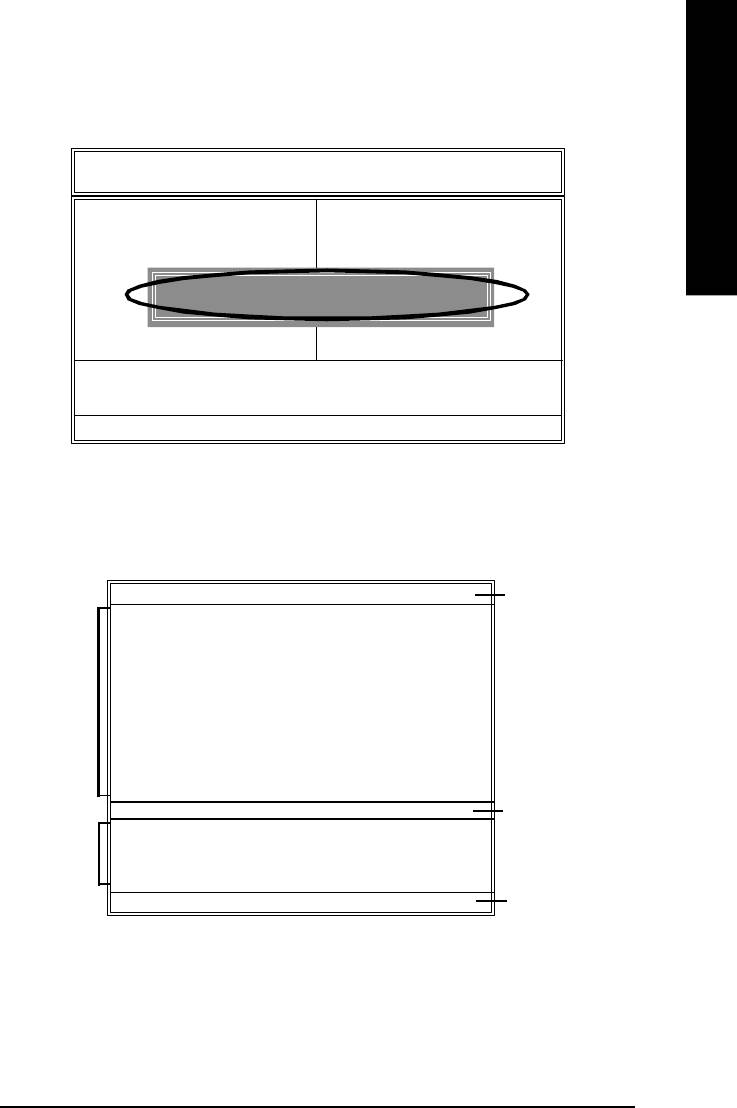
English
™
Step 2: Press F8 button on your keyboard and then Y button to enter the Q-Flash
utility.
AMIBIOS SIMPLE SETU P U TILITY - VERSION 2.00
(C ) 2001 American M egatr end s, Inc . All Ri ghts R es erv ed
STAN DARD CM OS SETUP INTEGRATED PERIPHERALS
BIOS FEATURES SETUP HARDWARE M ON ITOR & M ISC SETUP
CHIPSET FEATU RES SETUP SU PERVISOR PASSWORD
POWER MANAGEM EN T SETUP USER PASSWORD
ENTER DUAL BIOS/Q-FLASH UTILITY (Y/N) ? Y
PNP / PC I C ON FIGU RATION IDE H DD AU TO DETEC TION
LOAD FAIL-SAFE DEFAULTS SAVE & EXIT SETU P
LOAD OPTIM IZED DEFA U LTS EXIT WITHOUT SAVIN G
ESC: Quit hifg : S elec t Item F5: Old Values F6: Fail-Safe Values
F7: Opti mize d V alu es F8: Dual BIOS/Q-Flash F10:Sav e & Exit
Load Fail-Safe Defaults
™
Exploring the Q-Flash
/Dual BIOS utility screen
™
The Q-Flash
/Dual BIOS utility screen consists of the following key components.
Dual BIOS Utility
Dual BIOS utility bar
Boot Fro m.... ..... ..... .... ..... ..... ..... ..... ... M ain Bios
Main ROM Ty pe /Size... ........ ........ ..... SST 4 9L F0 03 A 256K
Backup ROM Ty pe/S ize... ....... ...... .... SST 4 9L F0 03 A 256K
Wide Range Protection Disable
Task menu for
Boot From M ain Bios
Dual BIOS utility
Auto Recov e ry E n ab l e
Halt On Err or Di sa bl e
Copy M ain ROM Data to Back up
Load Default Setti ng s
Sav e Settings to C M OS
Q-Flash Uti lity
TM
Q-Flash
utility title
Load M ain BIOS fr om Floppy
bar
Task menu for
Load Backup BIOS fro m F lop py
TM
Q-Flash
utility
Sav e Main BIOS to Flo ppy
Sav e Backup BIOS to Floppy
Enter : Run hi :M ov e ESC:Reset F10:Power Off
Action bar
- 67 -
Technical Reference
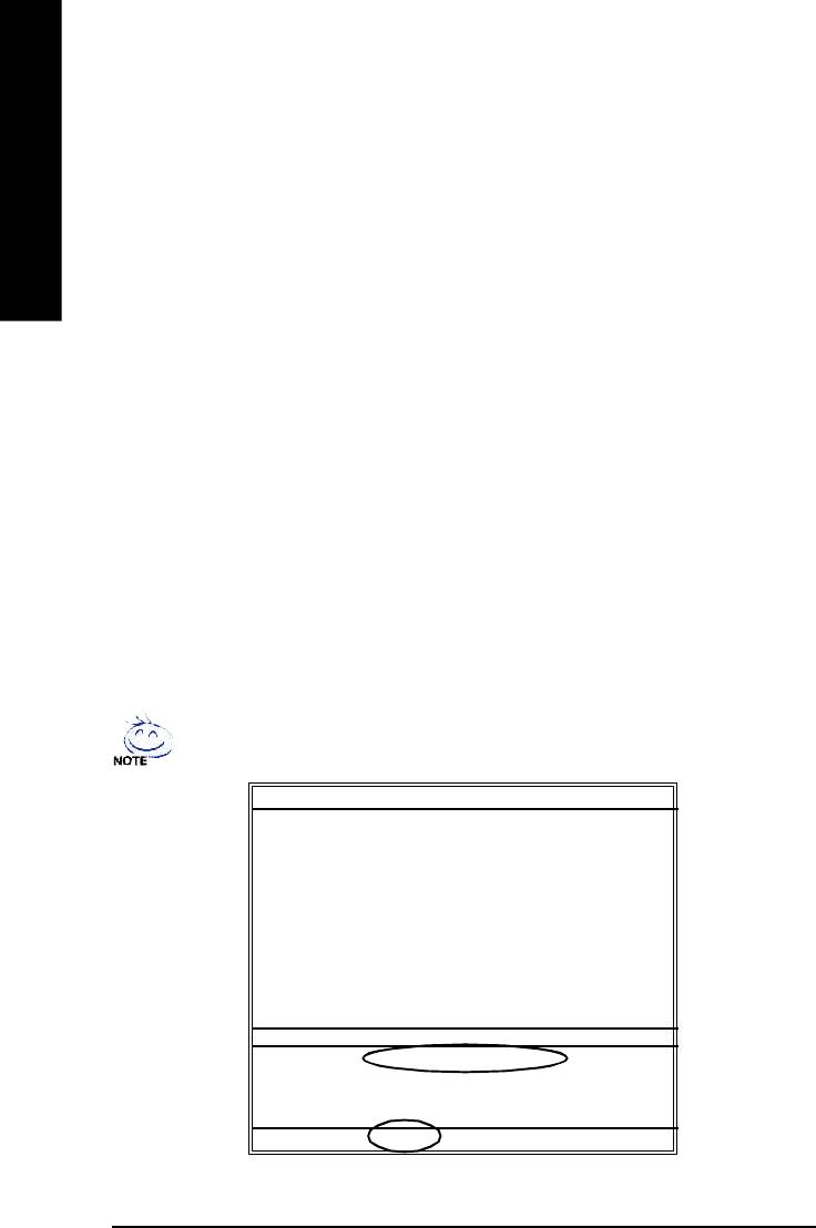
Task menu for Dual BIOS utility:
Contains the names of eight tasks and two item showing information about the BIOS ROM type.
Blocking a task and pressing Enter key on your keyboard to enable execution of the task.
™
English
Task menu for Q-Flash
utility:
Contains the names of four tasks. Blocking a task and pressing Enter key on your keyboard to
enable execution of the task.
Action bar:
™
Contains the names of four actions needed to operate the Q-Flash
/Dual BIOS utility. Pressing the
buttons mentioned on your keyboards to perform these actions.
™
Using the Q-Flash
utility:
™
This section tells you how to update BIOS using the Q-Flash
utility. As described in the “Before you
begin” section above, you must prepare a floppy disk having the BIOS file for your motherboard and
insert it to your computer. If you have already put the floppy disk into your system and have entered
™
the Q-Flash
utility, please follow the steps below to flash BIOS.
Steps:
1. Press arrow buttons on your keyboard to move the light bar to "Load Main BIOS from Floppy"
™
item in the Q-Flash
menu and press Enter button.
If you want to save the current BIOS for backup purpose, you can begin Step 1 with
"Save Main BIOS to Floppy" item.
Dual BIOS Utility
Boot Fro m.... ..... ..... .... ..... ..... ..... ..... ... M ain Bios
Main ROM Ty pe /Size... ........ ........ ..... SST 4 9L F0 03 A 256K
Backup ROM Ty pe/S ize... ....... ...... .... SST 4 9L F0 03 A 256K
Wide Range Protection Disable
Boot From M ain Bios
Auto Recov e ry Enable
Halt On Err or Di sa bl e
Copy M ain ROM Data to Back up
Load Default Setti ng s
Sav e Settings to C M OS
Q-Flash Uti lity
Load M ain BIOS fr om Floppy
Load Backup BIOS fro m F lop py
Sav e Main BIOS to Flo ppy
Sav e Backup BIOS to Floppy
Enter : Run hi :M ov e ESC:Reset F10:Power Off
- 68 -GA-8I865PE-L Motherboard
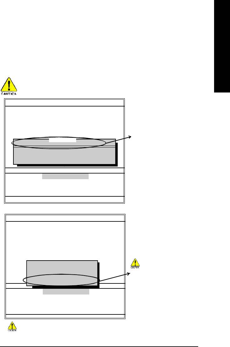
English
Later, you will see a box pop up showing the BIOS files you previously downloaded to the floppy
disk.
2.Move to the BIOS file you want to flash and press Enter.
In this example, we only download one BIOS file to the floppy disk so only one BIOS file,
7VRXP.F12, is listed.
Please confirm again you have the correct BIOS file for your motherboard.
Dual BIOS Utility
Boot Fro m.... ..... ..... .... ..... ..... ..... ..... ... M ain Bios
Main ROM Ty pe /Size... ........ ........ ..... SST 4 9L F0 03 A 256K
Backup ROM Ty pe/S ize... ....... ...... .... SST 4 9L F0 03 A 256K
Wide Range Protection Disable
Boot From M ain Bios
BIOS file in the floppy disk.
1 file(s) found
7VRXP.F12 256K
Auto Recov e ry Enable
Halt On Err or Di sa bl e
To tal s ize : 1 .3 9M Free size:1.14M
Copy M ain ROM Data to Back up
F5 : Refresh DEL : Delete
Load Default Setti ng s
Sav e Settings to C M OS
Q-Flash Uti lity
Load M ain BIOS fr om Floppy
Load Backup BIOS fro m F lop py
Sav e Main BIOS to Flo ppy
Sav e Backup BIOS to Floppy
Enter : Run hi :M ov e ESC:Reset F10:Power Off
After pressing Enter, you'll then see the progress of reading the BIOS file from the floppy disk.
Dual BIOS Utility
Boot Fro m.... ..... ..... .... ..... ..... ..... ..... ... M ain Bios
Main ROM Ty pe /Size... ........ ........ ..... SST 4 9L F0 03 A 256K
Backup ROM Ty pe/S ize... ....... ...... .... SST 4 9L F0 03 A 256K
Wide Range Protection Disable
Boot From M ain Bios
Auto Recov e ry Enable
Halt On Err or Di sa bl e
Reading BIOS fil e from flop py . ..
Copy M ain ROM Data to Back up
>>>>>>>>>>>>......................
Do not truning off power or reset
Load Default Setti ng s
Don’t Turn Off Power Or Reset System
Sav e Settings to C M OS
your system at this stage!!
Q-Flash Uti lity
Load M ain BIOS fr om Floppy
Load Backup BIOS fro m F lop py
Sav e Main BIOS to Flo ppy
Sav e Backup BIOS to Floppy
Enter : Run hi :M ov e ESC:Reset F10:Power Off
Please do not take out the floppy disk when it begins flashing BIOS.
- 69 -
Technical Reference
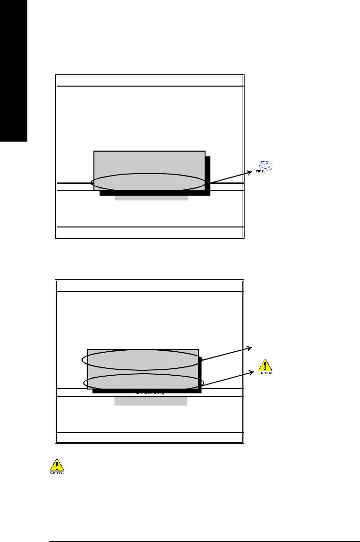
After BIOS file is read, you'll see a confirmation dialog box asking you "Are you sure to update
BIOS?"
Dual BIOS Utility
Boot Fro m.... ..... ..... .... ..... ..... ..... ..... ... M ain Bios
English
Main ROM Ty pe /Size... ........ ........ ..... SST 4 9L F0 03 A 256K
Backup ROM Ty pe/S ize... ....... ...... .... SST 4 9L F0 03 A 256K
Wide Range Protection Disable
Boot From Main Bios
Auto Recov e ry Enable
Halt On Err or Di sa bl e
CHECKSUM = 96D2
Copy M ain ROM Data to Back up
Are you sure to update BIOS?
Load Default Setti ng s
Sav e Settings to C M OS
You can press "Enter" to continue
[Enter] to conti nue o r [Esc] to a bo rt... ..
Q-Flash Uti lity
updating BIOS or "ESC" to abort.
Load M ain BIOS fr om Floppy
Load Backup BIOS fr om Floppy
Sav e Main BIOS to Flo ppy
Sav e Backup BIOS to Floppy
Enter : Run hi :M ov e ESC:Reset F10:Power Off
3. Press Y button on your keyboard after you are sure to update BIOS.
Then it will begin to update BIOS. The progress of updating BIOS will be displayed.
Dual BIOS Utility
Boot Fro m.... ..... ..... .... ..... ..... ..... ..... ... M ain Bios
Main ROM Ty pe /Size... ........ ........ ..... SST 4 9L F0 03 A 256K
Backup ROM Ty pe/S ize... ....... ...... .... SST 4 9L F0 03 A 256K
Wide Range Protection Disable
Boot From M ain Bios
Auto Recov e ry Enable
The progress of updating BIOS.
Programming N ow.......
Halt On Err or Di sa bl e
>>>>>>>>>>>>......................
Copy M ain ROM Data to Back up
Load Default Setti ng s
Don't Tu rn Off Po w e r O r R ese t S y stem
Do not turning off power or reset
Sav e Settings to C M OS
Q-Flash Uti lity
your system at this stage to avoid
Load M ain BIOS fr om Floppy
damaging your BIOS rom!!
Load Backup BIOS fro m F lop py
Sav e Main BIOS to Flo ppy
Sav e Backup BIOS to Floppy
Enter : Run hi :M ov e ESC:Reset F10:Power Off
Please do not take out the floppy disk when it begins flashing BIOS.
- 70 -GA-8I865PE-L Motherboard
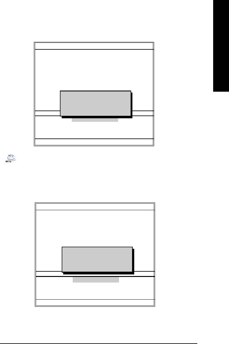
English
™
4. Press any keys to return to the Q-Flash
menu when the BIOS updating procedure is completed.
Dual BIOS Utility
Boot Fro m.... ..... ..... .... ..... ..... ..... ..... ... M ain Bios
Main ROM Ty pe /Size... ........ ........ ..... SST 4 9L F0 03 A 256K
Backup ROM Ty pe/S ize... ....... ...... .... SST 4 9L F0 03 A 256K
Wide Range Protection Disa bl e
Boot From Main Bios
Auto Recov e ry Enable
Halt On Err or Di sa bl e
Copy M ain ROM Data to Back up
!! C opy BIOS completed - Pas s !!
Load Default Setti ng s
Please press any key to contin ue
Sav e Settings to C M OS
Q-Flash Uti lity
Load M ain BIOS fr om Floppy
Load Backup BIOS fro m F lop py
Sav e Main BIOS to Flo ppy
Sav e Backup BIOS to Floppy
Enter : Run hi :M ov e ESC:Reset F10:Power Off
You can repeat Step 1 to 4 to flash the backup BIOS, too.
™
5. Press Esc and then Y button to exit the Q-Flash
utility. The computer will restart automatically
™
after you exit Q-Flash
.
Dual BIOS Utility
Boot Fro m.... ..... ..... .... ..... ..... ..... ..... ... M ain Bios
Main ROM Ty pe /Size... ........ ........ ..... SST 4 9L F0 03 A 256K
Backup ROM Ty pe/S ize... ....... ...... .... SST 4 9L F0 03 A 256K
Wide Range Protection Disable
Boot From M ain Bios
Auto Recov e ry E n ab l e
Halt On Err or Di sa bl e
Copy M ain ROM Data to Back up
Are you sure to R ESET ?
Load Default Setti ng s
[Enter] to continue or [Esc] to ab or t...
Sav e Settings to C M OS
Q-Flash Uti lity
Load M ain BIOS fr om Floppy
Load Backup BIOS fro m F lop py
Sav e Main BIOS to Flo ppy
Sav e Backup BIOS to Floppy
Enter : Run hi :M ov e ESC:Reset F10:Power Off
- 71 -
Technical Reference
After system reboots, you may find the BIOS version on your boot screen becomes the one you
flashed.
Ame r ic an Rel e as e :0 8 /2 3/ 200 2
Megatrends AMI BI OS ( C) 19 9 9 A merican Megatrend
English
7VRXP F12
The BIOS file becomes
AMD-Athlon(tm) Pro ce sso r- 133 3MHz
Check System Heal th !
Checking NVRAM. ..Upd at e OK
F12 after updating
262144KB
DEL:Steup/Dual BIOS/Q-Flash F8:Boot Me nu F1 2:N etw or k b oo t TAB: Logo
Auto-Detecting Pri Master..IDE Hard Disk
Auto-Detecting Pri Slave...Not Detected
Auto-Detecting Sec Master..ATAPI CDROM
Auto-Detecting Sec Slave.. Not Detected
( C ) Amer ica n Meg atr end s Inc .,
62-2003-001199-00101111-040201-KT333-GA7VRXP1-
The following is an AMI BIOS menu screen. However, you can also find similar option in
AWARD BIOS menu.
6. Press Del to enter BIOS menu after system reboots. When you are in BIOS menu, move to Load
Fail-Safe Defaults item and press Enter to load BIOS Fail-Safe Defaults. Normally the system
redetects all devices after BIOS has been upgraded. Therefore, we highly recommend reloading
the BIOS defaults after BIOS has been upgraded.
AMIBIOS SIMPLE SETU P U TILITY - VERSION 2.00
(C ) 2001 American M egatr end s, Inc . All Ri ghts R es erv ed
STAN DARD CM OS SETUP INTEGRATED PERIPHERALS
BIOS FEATURES SETUP HARDWARE M ON ITOR & M ISC SETUP
CHIPSET FEATU RES SETUP SU PERVISOR PASSWORD
POWER MANAGEM EN T SETUP USER PASSWORD
PNP / PC I C ON FIGU RATION IDE H DD AU TO DETEC TION
LOAD FAIL-SAFE DEFAULTS SAVE & EXIT SETU P
LOAD OPTIM IZED DEFA U LTS EXIT WITHOUT SAVIN G
Press Enter on
ESC: Quit hifg : S elec t Item F5: Old Values F6: Fail-Safe Values
your keyboard
F7: Opti mize d V alu es F8: Dual BIOS/Q-Flash F10:Sav e & Exit
Load Fail-Safe Defaults
- 72 -GA-8I865PE-L Motherboard
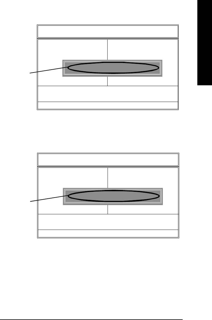
English
AMIBIOS SIMPLE SETU P U TILITY - VERSION 2.00
(C ) 2001 American M egatr end s, Inc . All Ri ghts R es erv ed
STAN DARD CM OS SETUP INTEGRATED PERIPHERALS
BIOS FEATURES SETUP HARDWARE M ON ITOR & M ISC SETUP
CHIPSET FEATU RES SETUP SU PERVISOR PASSWORD
POWER MANAGEM EN T SETUP USER PASSWORD
Load Fail-Safe Defaults (Y/N)? Y
PNP / PC I C ON FIGU RATION IDE H DD AU TO DETEC TION
LOAD FAIL-SAFE DEFAULTS SAVE & EXIT SETU P
Press Y on your
LOAD OPTIM IZED DEFA U LTS EXIT WITHOUT SAVIN G
keyboard to load
ESC: Quit hifg : S elec t Item F5: Old Values F6: Fail-Safe Values
defaults.
F7: Opti mize d V alu es F8: Dual BIOS/Q-Flash F10:Sav e & Exit
Load Fail-Safe Defaults
7. Select Save & Exit Setup item to save the settings to CMOS and exit the BIOS menu. System
will reboot after you exit the BIOS menu. The procedure is completed.
AMIBIOS SIMPLE SETU P U TILITY - VERSION 2.00
(C ) 2001 American M egatr end s, Inc . All Ri ghts R es erv ed
STAN DARD CM OS SETUP INTEGRATED PERIPHERALS
BIOS FEATURES SETUP HARDWARE MONITOR & MISC SETUP
CHIPSET FEATU RES SETUP SU PERVISOR PASSWORD
POWER MANAGEM EN T SETUP USER PASSWORD
SAVE to CM OS and EXIT (Y/N) ? Y
PNP / PC I C ON FIGU RATION IDE HDD AUTO DETEC TION
LOAD FAIL-SAFE DEFAULTS SAVE & EXIT SETU P
Press Y on your
LOAD OPTIM IZED DEFA U LTS EXIT WITHOUT SAVIN G
keyboard to
ESC: Quit hifg : S elec t Item F5: Old Values F6: Fail-Safe Values
save and exit.
F7: Opti mize d V alu es F8: Dual BIOS/Q-Flash F10:Sav e & Exit
Load Fail-Safe Defaults
- 73 -
Technical Reference
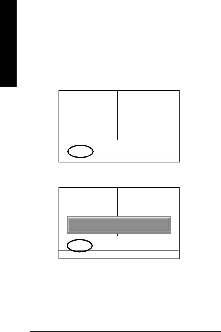
Part Two:
™
Updating BIOS with Q-Flash
Utility on Single-BIOS Motherboards.
™
This part guides users of single-BIOS motherboards how to update BIOS using the Q-Flash
utility.
English
™
Entering the Q-Flash
utility:
™
Step1: To use the Q-Flash
utility, you must press Del in the boot screen to enter BIOS menu.
CM OS Setup Utility - C op y r igh t ( C ) 1984- 200 2 A w ar d S oftwa re
}Standard CM OS Features Top Perfo rm a nc e
}Advanced BIOS Featur es Load Fail-Safe Defaults
} Integrated Peripherals L oa d Optim iz e d Defau lts
} Pow er M anagement Setup Set Superv isor Password
}PnP/PCI Config ura tions Set U se r Pa ssw o rd
}PC H ealth Status Save & Exit S etup
} Frequency/Voltage Control Ex it Without Saving
ESC:Quit higf:Select Item
F8: Q-Flash F10:Sav e & Ex it Setup
Tim e, D ate, H ar d Di sk Ty pe. ..
™
2. Press F8 on your keyboard and then Y button to enter the Q-Flash
utility.
CM OS Setup Utility - C op y r igh t ( C ) 1984- 200 2 A w ar d S oftwa re
}Standard CM OS Features Top Perfo rm a nc e
}Advanced BIOS Featur es Load Fail-Safe Defaults
} Integrated Peripherals L oa d Optim iz e d Defau lts
} Pow er M anagement Setup Set Superv isor Password
}PnP/PCI Config ura tions Set U se r Pa ssw o rd
}PC H ealth Status Save & Exit S etup
Enter Q-Flash Utility (Y/N) ? Y
} Frequency/Voltage Control Ex it Without Saving
ESC:Quit higf:Select Item
F8: Q-Flash F10:Sav e & Ex it Setup
Tim e, D ate, H ar d Di sk Ty pe. ..
- 74 -GA-8I865PE-L Motherboard
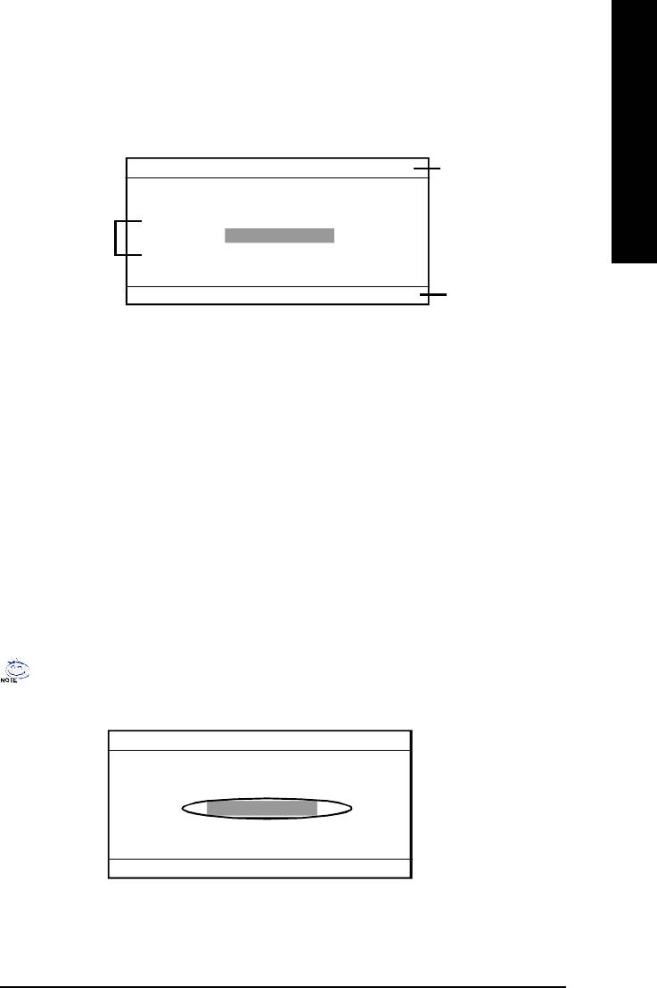
English
™
Exploring the Q-Flash
utility screen
™
The Q-Flash
BIOS utility screen consists of the following key components.
Q-Flash Utili ty V1 .30
The Qflash utility
Flash Ty pe/Size................SST 49LF002A 256K
title bar
Keep DMI DataEnable
Task menu for the
Update BIOS fro m F lop py
Q-flash utility
Save BIOS to Flo ppy
Enter: Run h/i: M ove ESC: Reset F10: Pow er Off
Action bar
™
Task menu for the Q-Flash
utility: Contains the names of three tasks. Blocking a task and
pressing Enter key on your keyboard to enable execution of the task.
™
Action bar: Contains the names of four actions needed to operate the Q-Flash
utility. Pressing the
buttons mentioned on your keyboard to perform these actions.
™
Using the Q-Flash
utility:
™
This section tells you how to update BIOS using the Q-Flash
utility. As described in the "Before you
begin" section above, you must prepare a floppy disk having the BIOS file for your motherboard and
insert it to your computer. If you have already put the floppy disk into your system and have enter the
™
Q-Flash
utility, please follow the steps below to flash BIOS.
Steps:
1. Press arrow buttons on your keyboard to move the light bar to "Load Main BIOS from Floppy"
™
item in the Q-Flash
menu and press Enter button.
If you want to save the current BIOS for backup purpose, you can begin Step 1 with Save
Main BIOS to Floppy item.
Q-Flash Utili ty V1 .30
Flash Ty pe/Size................SST 49LF002A 256K
Keep DMI DataEnable
Update BIOS fro m F lop py
Save BIOS to Flo ppy
Enter: Run h/i: M ove ESC: Reset F10: Pow er Off
- 75 -
Technical Reference
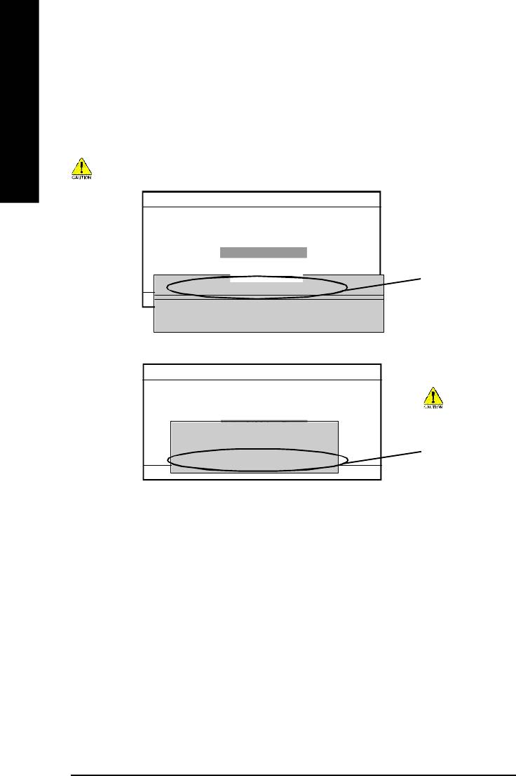
Later, you will see a box showing the BIOS files you downloaded to the floppy disk.
In this example, we only download one BIOS for this board, 8GE800.F4 so only one BIOS file is listed.
2.Highlight the BIOS file you want to flash and press Enter button on your keyboard to enable reading
English
from the BIOS file from the floppy.
Please confirm again you have the correct BIOS file for your motherboard.
Q-Flash Utili ty V1 .30
Flash Ty pe/Size................SST 49LF002A 256K
Keep DMI DataEnable
Update BIOS fro m F lop py
Save BIOS to Flo ppy
1 File(s) found
B IO S fi le i n th e
8GE800.F4 256K
Enter: Run h/i: M ove ESC: Reset F10: Pow er Off
floppy.
To tal S ize : 1 .3 9M Free Size: 1.14M
F5: Refr es h D EL : Del ete
Q-Flash Utili ty V1 .30
Flash Ty pe/Size................SST 49LF002A 256K
Keep DMI DataEnable
Do not turning
Update BIOS fro m F lop py
Reading BIOS fi le from floppy .........
Save BIOS to Flo ppy
power or reset your
>>>>>>>>...........................
system at this
Don't turn off Pow er Or RES ET Sy stem
stage!
Enter: Run h/i: M ove ESC: Reset F10: Pow er Off
After BIOS file is read, you’ll see a confirmation dialog box asking you
"Are you sure to update BIOS?"
- 76 -GA-8I865PE-L Motherboard
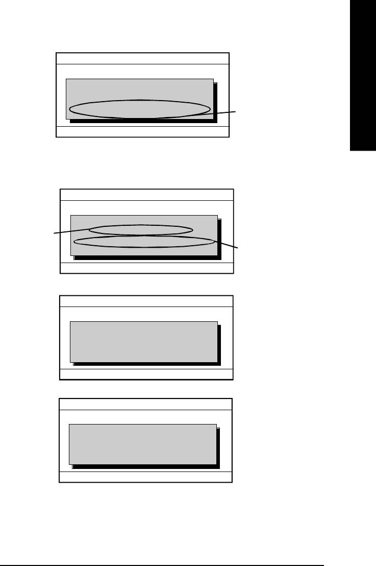
English
Q-Flash Utili ty V1 .30
Flash Ty pe/Size................SST 49LF002A 256K
CHECKSUM = AC03
Keep DMI DataEnable
Are you sure to u pdate BI OS?
Update BIOS fro m F lop py
You can press "Enter" to
Save BIOS to Flo ppy
[Enter] to continue updating BIOS or "ESC" to ab or t.
continue updating BIOS
or "ESC" to abort.
Enter: Run h/i: M ove ESC: Reset F10: Pow er Off
3. Press Y button if you make sure to update BIOS.
Then it will begin to update BIOS. The progress of updating will be shown at the same time.
Q-Flash Utili ty V1 .30
Flash Ty pe/Size................SST 49LF002A 256K
Updating BIOS N o w ...
Keep DMI DataEnable
>>>>>>>>>>>>>.................
Do not turning off power
The porcess of
Update BIOS fro m F lop py
Do not Tur n Off Pow er On R ESET Sy s tem
Save BIOS to Flo ppy
or reset your system at
updating BIOS
this stage!!
Enter: Run h/i: M ove ESC: Reset F10: Pow er Off
™
4. Press any keys to return to the Q-Flash
menu when the BIOS updating procedure is completed.
Q-Flash Utili ty V1 .30
Flash Ty pe/Size................SST 49LF002A 256K
Keep DMI DataEnable
!! Copy BIOS completed - pass !!
Update BIOS fro m F lop py
Please press any key to continue. ...
Save BIOS to Flo ppy
Enter: Run h/i: M ove ESC: Reset F10: Pow er Off
™
5. Press Esc and then Enter to exit the Q-Flash
utility. System will restart.
Q-Flash Utili ty V1 .30
Flash Ty pe/Size................SST 49LF002A 256K
Keep DMI DataEnable
Are you sure to RES ET?
Update BIOS fro m F lop py
[Enter] to co ntinue or [Esc] to a bor t....
Save BIOS to Flo ppy
Enter: Run h/i: M ove ESC: Reset F10: Pow er Off
6. Press Del to enter BIOS menu after system reboots and load BIOS Fail-Safe Defaults. See how
to load BIOS Fail-Safe Defaults, please kindly refer to Step 6 to 7 in Part One.
Congratulation!! You have updated BIOS successfully!!
- 77 -
Technical Reference
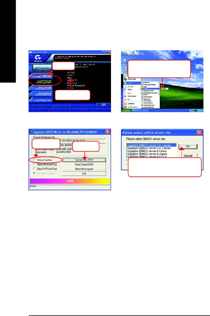
Method 2: @ BIOS Utility
TM
If you don't have DOS boot disk, we recommend that you used Gigabyte @BIOS
program to
flash BIOS.
English
Press here.
2.Click"Start"-"Programs"-
"GIGABYTE"-"@BIOS"
1.Click "@BIOS"
(2)
(1)
3.Click "P".
4.Click here.
5. Please select @BIOS sever site,
then Click "OK".
(3)
(4)
Methods and steps:
I. Update BIOS through Internet
a. Click "Internet Update" icon
b. Click "Update New BIOS" icon
TM
c. Select @BIOS
sever
d. Select the exact model name on your motherboard
e. System will automatically download and update the BIOS.
- 78 -GA-8I865PE-L Motherboard

English
II. Update BIOS NOT through Internet:
a. Do not click "Internet Update" icon
b. Click "Update New BIOS"
c. Please select "All Files" in dialog box while opening the old file.
d. Please search for BIOS unzip file, downloading from internet or any other methods (such as:
8I865PE-L.F1).
e. Complete update process following the instruction.
III. Save BIOS
In the very beginning, there is "Save Current BIOS" icon shown in dialog box. It means to save the
current BIOS version.
IV. Check out supported motherboard and Flash ROM:
In the very beginning, there is "About this program" icon shown in dialog box. It can help you check
out which kind of motherboard and which brand of Flash ROM are supported.
Note:
a. In method I, if it shows two or more motherboard's model names to be selected, please make
sure your motherboard's model name again. Selecting wrong model name will cause the
system unbooted.
b. In method II, be sure that motherboard's model name in BIOS unzip file are the same as your
motherboard's. Otherwise, your system won't boot.
TM
c. In method I, if the BIOS file you need cannot be found in @BIOS
server, please go onto
Gigabyte's web site for downloading and updating it according to method II.
d. Please note that any interruption during updating will cause system unbooted
- 79 -
Technical Reference
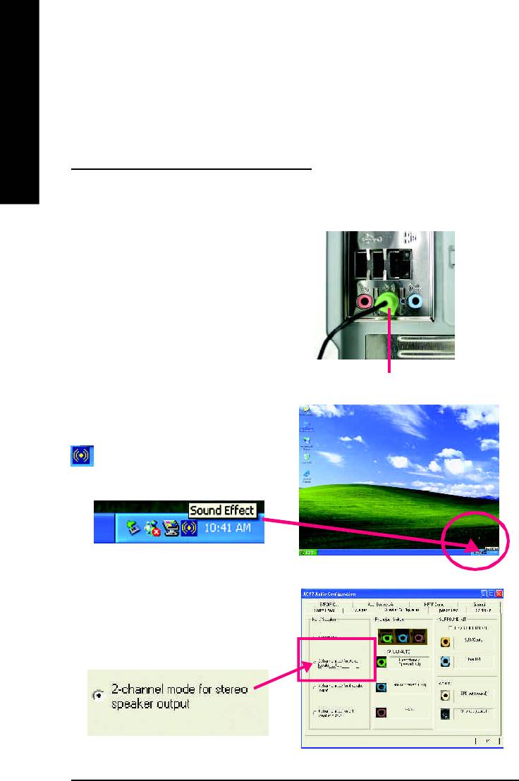
Revision History2-/4-/6-Channel Audio Function Introduction
The installation of windows 98SE/2K/ME/XP is very simple. Please follow next step to install the
English
function!
Stereo Speakers Connection and Settings:
We recommend that you use the speaker with amplifier to acqiire the best sound effect if the stereo output
is applied.
STEP 1:
Connect the stereo speakers or earphone to "Line
Out".
Line Out
STEP 2 :
After installation of the audio driver, you'll find an
icon on the taskbar's status area. Click the
audio icon "Sound Effect" from the windows tray at
the bottom of the screen.
STEP 3:
Select "Speaker Configuration", and choose the
"2 channel for stereo speakers out put".
- 80 -GA-8I865PE-L Motherboard
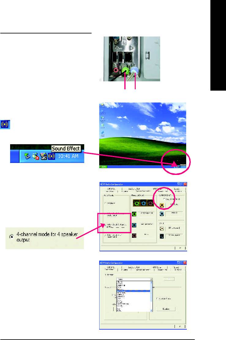
English
4 Channel Analog Audio Output Mode
STEP 1 :
Connect the front channels to "Line Out",
the rear channels to "Line In".
Line Out Line In
STEP 2 :
After installation of the audio driver, you'll find an
icon on the taskbar's status area. Click the
audio icon "Sound Effect" from the windows tray at
the bottom of the screen.
STEP 3 :
Select "Speaker Configuration", and choose the
"4 channel for 4 speakers out put".
Disable "Only SURROUND-KIT", and press
"OK".
When the "Environment settings" is "None", the
sound would be performed as stereo mode
(2 channels output). Please select the other
settings for 4 channels output.
- 81 -
Technical Reference
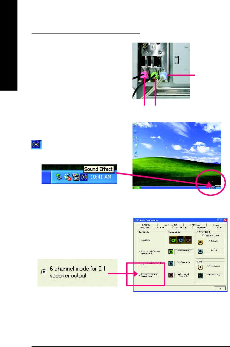
Basic 6 Channel Analog Audio Output Mode
Use the back audio panel to connect the audio out-
put without any additional module.
English
STEP 1 :
Connect the front channels to "Line Out",the rear
Line In
channels to "Line In", and the Center/Subwoofer
channels to "MIC In".
M IC In
Line Out
STEP 2 :
After installation of the audio driver, you'll find an
icon on the taskbar's status area. Click the
audio icon "Sound Effect" from the windows tray at
the bottom of the screen.
STEP 3 :
Select "Speaker Configuration", and choose the
"6 channel for 5.1 speakers out put".
Disable "Only SURROUND-KIT" and press "OK".
- 82 -GA-8I865PE-L Motherboard
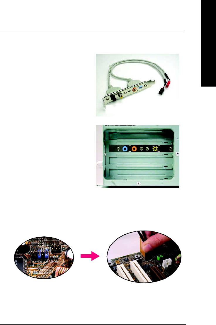
English
Advanced 6 Channel Analog Audio Output M ode (using Audio Combo Kit,Optional Device):
(Audio Combo Kit provides SPDIF output port : optical & coaxis and SURROUND-KIT : Rear R/L & CEN
/Subwoofer)
SURROUND-KIT access analog output to rear
channels and Center/Subwoofer channels. It is the
best solution if you need 6 channel output, Line In
and MIC at the same time. "SURROUND-KIT" is
included in the GIGABYTE unique "Audio Com bo
Kit" as picture.
STEP 1 :
Insert the "SURROUND-KIT" in the back of the case
,and fix it with the screw.
STEP 2 :
Connect the "SURROUND-KIT" to SUR_CEN on
the M/B.
- 83 -
Technical Reference
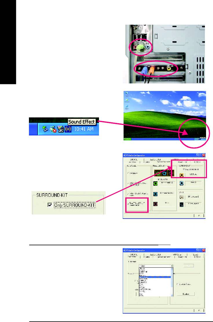
STEP 3 :
Connect the front channels to back audio panel's
"Line Out", the rear channels to SURROUND-KIT's
REAR R/L, and the Center/Subwoofer channels to
English
SURROUND-KIT's SUB CENTER.
STEP 4 :
Click the audio icon "Sound Effect" from the win-
dows tray at the bottom of the screen.
STEP 5 :
Select "Speaker Configuration", and choose the
"6 channel for 5.1 speakers out put".
Enable "Only SURROUND-KIT" and press "OK".
Basic & Advanced 6 Channel Analog Audio Output ModeNotes:
When the "Environment settings" is "None", the sound
would be perform ed as stereo m ode(2 channels
output). Please select the other settings for 6
channels output.
- 84 -GA-8I865PE-L Motherboard
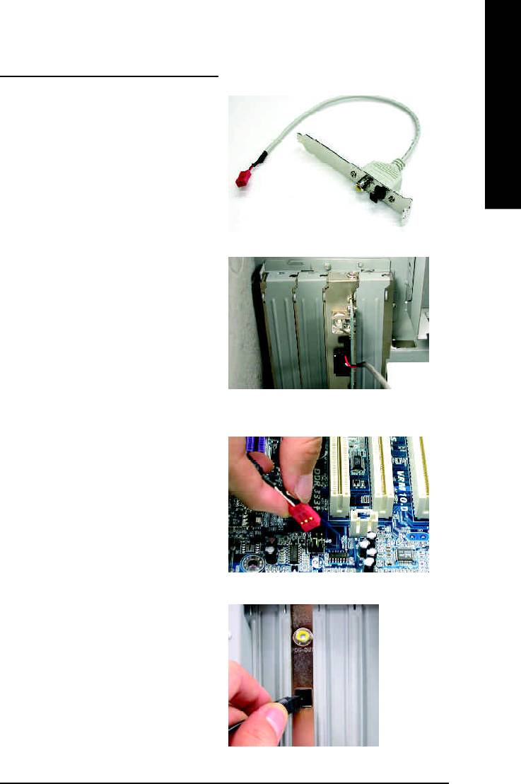
English
SPDIF Output Device (Optional Device)
A "SPDIF output" device is available on the
motherboard. Cable with rear bracket is provided
and could link to the "SPDIF output" connector (As
picture.) For the further linkage to decoder, rear
bracket provides coaxial cable and Fiber
connecting port.
1. Connect the SPDIF output device to the rear
bracket of PC, and fix it with screw.
2. Connect SPDIF device to the motherboard.
3. Connect SPDIF to the SPDIF decoder.
- 85 -
Technical Reference
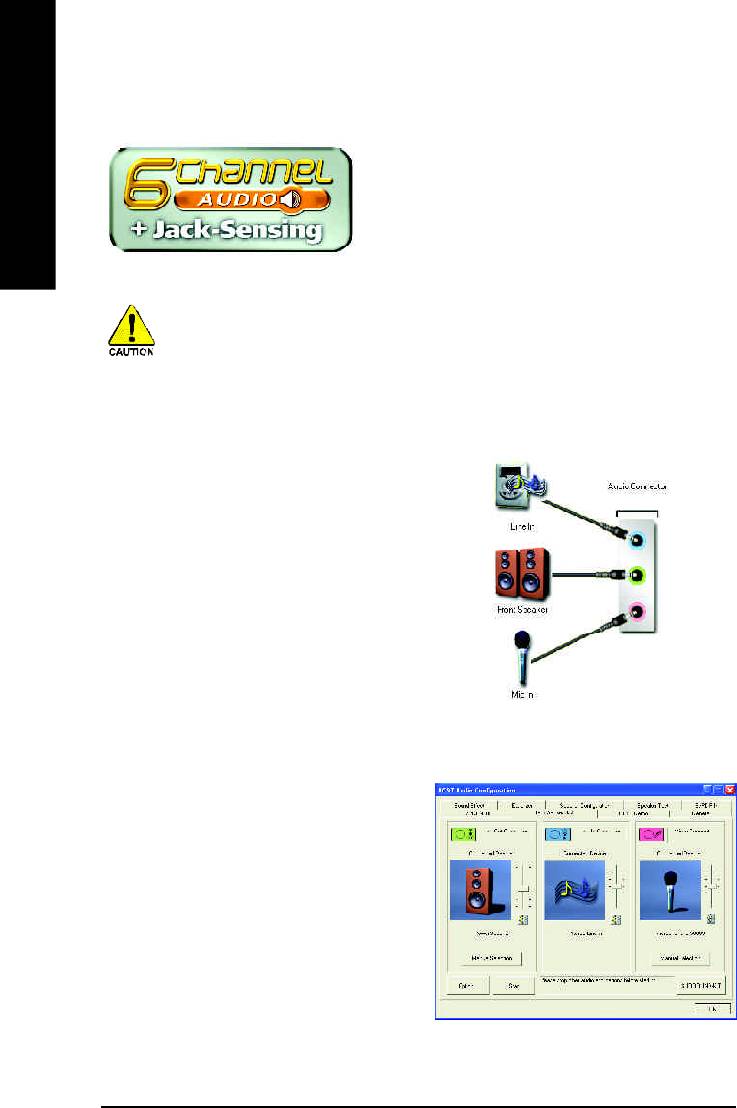
Jack-Sensing Introduction
Jack-Sensing provides audio connectors error-detection
English
function.
Install Microsoft DirectX8.1 or later version before to enable Jack-Sensing support for Windows
98/98SE/2000/ME.
Jack-Sensing includes 2 parts: AUTO and M ANUAL. Following is an example for 2 channels
(Windows XP):
Introduction of audio connectors
You may connect CDROM, Walkman or others
audio input devices to Line In jack, speakers,
earphone or others output devices to Line Out jack,
and microphone to M IC In jack.
Auto-detecting:
Please connect the devices to the right jacks as
above. A window will appear as right picture if you
setup the devices properly.
Please note that 3D audio function will only appear
when 3D audio inputs.
- 86 -GA-8I865PE-L Motherboard
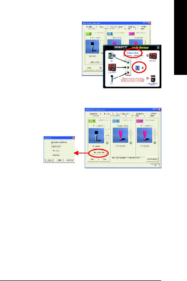
English
If you set wrong with the connectors, the warning
message will come out as right picture.
Manual setting:
If the device picture shows different from what you
set, please press "Manual Selection" to set.
- 87 -
Technical Reference
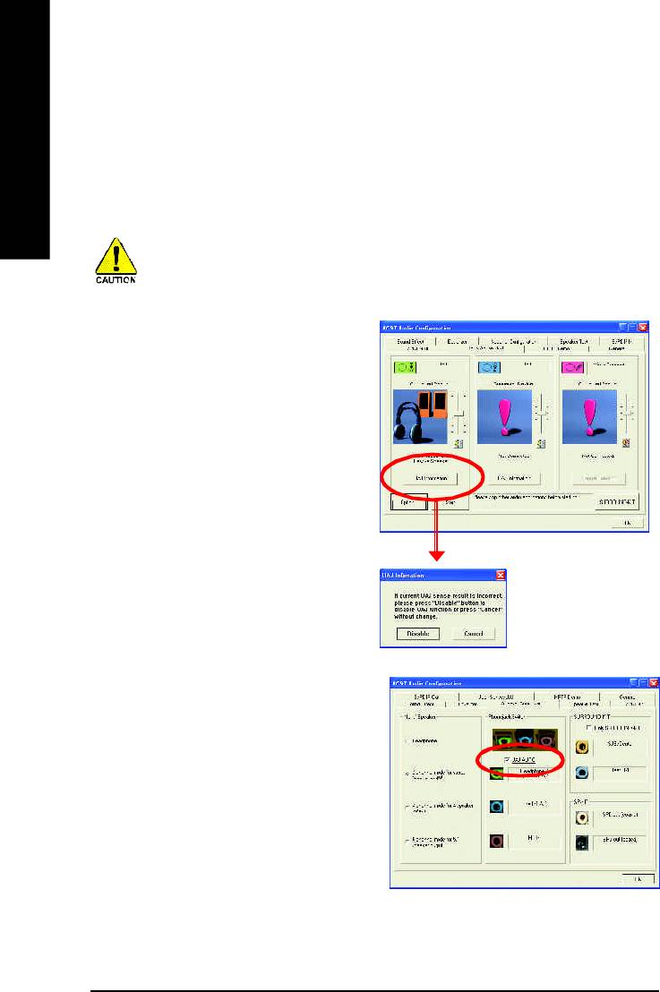
UAJ Introduction
UAJ (Universal Audio Jack) has a very smart feature: It will switch signal automatically when user plugs
his audio device to the wrong jack (Line-in/ Line-out).
English
That means users do not need to worry the Audio device should be plug in Line-in or Line-out jack, the
device will work perfectly after UAJ is activated.
Install Microsoft DirectX8.1 or later version before to enable UAJ support for Windows 98/98SE/
2000/ME.
PS. If UAJ couldn't work as expected, please
disable this function by pressing button
"UAJ information". And then Jack-Sense function
will awake and auto-detect if the Audio device is
plugged to the right jack (Line-in or Line-out).
Reviving UAJ:
You can click "UAJ AUTO" to revive UAJ function.
- 88 -GA-8I865PE-L Motherboard
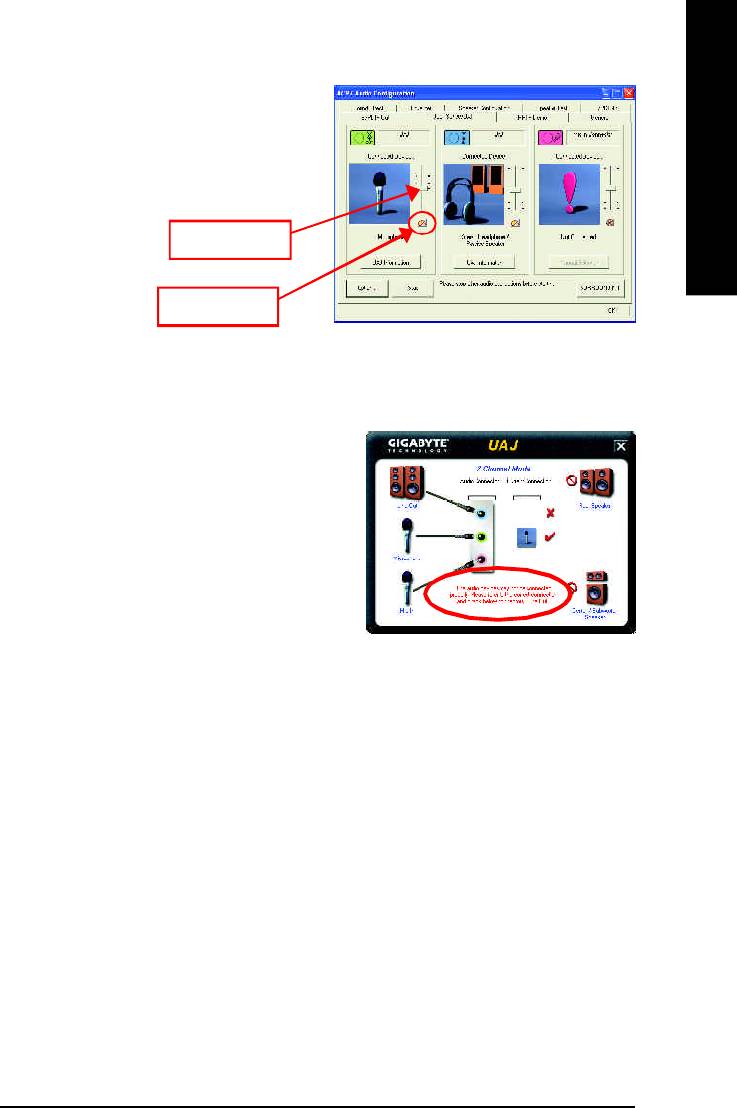
English
Adjusting Sound Volume:
You can adjust sound volume by moving lever.
Also you can mute sound by pressing the
"mute button".
Volume lever
Mute button
If there is only Line-in device plugged, UAJ will
remind you there is no any Line-out device plugged
in.
Note:
If you want to use AUX IN function, you must disable UAJ function from the Speaker Configuration item
in the AC97 Audio Configuation menu. After that, you'll have to use the Line-In volume lever in the
"Volume Control" menu to adjust the volume because AUX IN and Line-In functions are controlled by the
same audio signals.
- 89 -
Technical Reference

Xpress Recovery Introduction
What is Xpress Recovery?
English
Xpress Recovery utility is an utility for backing up and restoring O.S. partition . If the hard drive
can not work properly, you can restore it to the original state.
1. It supports FAT16, FAT32, NTFS format .
2. It must be connected to IDE1 Master .
3. It's only allows you to install one O.S .
4. It must be used with IDE hard disk supporting HPA .
5. The first partition must be set as the boot partition. When the boot partition is backed up,
please do not change the its size.
6. It is not recommend to use Xpress Recovery if you had ever used Ghost to return boot
managemer to NTFS format.
1. System data and hard disk's reading/writing speed will affect backing up speed.
2. We recommend that you install Xpress Recovery immediately after installing O.S ,
drivers and applications.
How to use the Xpress Recovery
There are two ways to enter the Xpress Recovery utility. (see the below)
1. Text Mode: press F9 during powering on the computer.
Press F9 during powering on the computer .
Awar d Modul ar BIO S v6.00 PG, An Energy Star A l ly
Copyright (C) 1984-2002, Award Software, Inc.
Intel 865PE AGPSet BIOS for 8IPE1000MT F1
Check System Health OK
.
.
.
Press DEL to enter SETUP / Q-Flash, F9 For Xpress Recovery
F9 For Xpress Recovery
08/16/2002-I845GE-6A69YG01C-00
2. BMP Mode: boot from CD-ROM
Please go to "Advanced BIOS" setting menu and set boot from CD-ROM , then save and exit the
BIOS menu . Later,please insert MB driver CD into your drive when "Boot from CD:" appears at the
bottom of the screen , press any key to enter Xpress Recovery.
.
.
Verifying DMI Pool Data
Boot from CD:
Boot from CD:
- 90 -GA-8I865PE-L Motherboard

English
You can highlight the item by using the arrows keys on your keyboard and
enter key to enter the menu.
Text Mode:
Xpress Recovery V1.0 (C) Copy Right 2003. GIGABYTE Technilogy CO. , Ltd.
1. Execute Backup Utility
2. Execute Restore Utility
3. Remove Backup Im age
4. Exit and Restart
BMP Mode:
Xpress Recovery V1.0 (C) Copy Right 2003. GIGABYTE Technilogy CO. , Ltd.
1. Execute Backup Utility
2. Execute Restore Utility
3. Remove Backup Im age
4. Exit and Restart
If you ever entered Xpress Recovery by booting from CD-ROM, you'll still be
directed to BMP mode by pressing F9 in the bootup screen.
- 91 -
Technical Reference

1.Execute Backup Utility:
! Press B to Backup your System or Esc to Exit
The Backup utility will scan the system automatically and back up it.
English
The backed up data will be saved as an hidden image .
2.Execute Restore Utility:
! This program will recover your system to factory default.
Press R to recover your system.
Press Esc to exit
Restore the backup image to the original state.
3.Remove Backup Image:
! Are you sure to remove backup image? (Y/N)
Remove the backup image.
4.Exit and Restart:
Exit and restart your computer.
- 92 -GA-8I865PE-L Motherboard
Оглавление
- DECLARATION OF CONFORMITY
- Chapter 5 Appendix
- FAQ
- Troubleshooting
- Technical Support/RMA Sheet
- Acronyms


