Gigabyte GA-MA790GP-UD3H: инструкция
Инструкция к Материнской Плате Gigabyte GA-MA790GP-UD3H
GA-MA790GP-UD3H
AM2+/AM2 socket motherboard for
TM
TM
AMD Phenom
II X4 processor/AMD Phenom
II X3 processor/
TM
TM
AMD Phenom
FX processor/AMD Phenom
X4 processor/
TM
TM
AMD Phenom
X3 processor/AMD Athlon
X2 processor/
TM
TM
AMD Athlon
processor/AMD Sempron
X2 processor/
TM
AMD Sempron
processor
User's Manual
Rev. 1001
12ME-MA79PU3-1001R

GA-MA790GP-UD3H
May 7, 2009
Motherboard
May 7, 2009
GA-MA790GP-UD3H
Motherboard

Copyright
© 2009 GIGA-BYTE TECHNOLOGY CO., LTD. All rights reserved.
The trademarks mentioned in this manual are legally registered to their respective owners.
Disclaimer
Information in this manual is protected by copyright laws and is the property of GIGABYTE.
Changes to the specifications and features in this manual may be made by GIGABYTE without prior
notice. No part of this manual may be reproduced, copied, translated, transmitted, or published in any
form or by any means without GIGABYTE's prior written permission.
Documentation Classifications
In order to assist in the use of this product, GIGABYTE provides the following types of documentations:
For quick set-up of the product, read the Quick Installation Guide included with the product.
For detailed product information, carefully read the User's Manual.
For instructions on how to use GIGABYTE's unique features, read or download the information
on/from the Support&Downloads\Motherboard\Technology Guide page on our website.
For product-related information, check on our website at:
http://www.gigabyte.com.tw
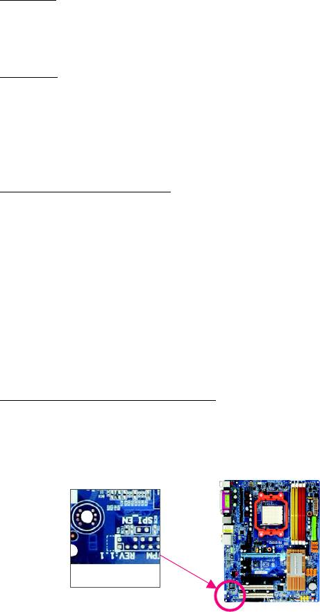
Identifying Your Motherboard Revision
The revision number on your motherboard looks like this: "REV: X.X." For example, "REV: 1.0"
means the revision of the motherboard is 1.0. Check your motherboard revision before updating
motherboard BIOS, drivers, or when looking for technical information.
Example:

Table of Contents
Box Contents ................................................................................................................. 6
Optional Items ................................................................................................................. 6
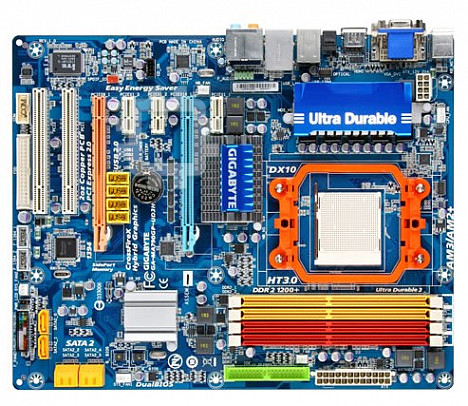
GA-MA790GP-UD3H Motherboard Layout .................................................................... 7
Block Diagram................................................................................................................ 8
Chapter 1 Hardware Installation .................................................................................... 9
1-1 Installation Precautions ..................................................................................... 9
1-2 Product Specifications .................................................................................... 10
1-3 Installing the CPU and CPU Cooler.............................................................. 13
1-3-1 Installing the CPU ................................................................................................ 13
1-3-2 Installing the CPU Cooler ................................................................................... 15
1-4 Installing the Memory ..................................................................................... 16
1-4-1 Dual Channel Memory Configuration................................................................ 16
1-4-2 Installing a Memory............................................................................................. 17
1-5 Installing an Expansion Card ......................................................................... 18
TM
1-6 Enabling the ATI Hybrid CrossFireX
Function ............................................ 19
TM
1-7 Setup of ATI CrossFireX
Configuration ........................................................ 20
1-8 Back Panel Connectors ................................................................................. 21
1-9 Internal Connectors ........................................................................................ 24
Chapter 2 BIOS Setup................................................................................................. 35
2-1 Startup Screen ................................................................................................ 36
2-2 The Main Menu .............................................................................................. 37
2-3 MB Intelligent Tweaker(M.I.T.) ....................................................................... 39
2-4 Standard CMOS Features ............................................................................. 44
2-5 Advanced BIOS Features.............................................................................. 46
2-6 Integrated Peripherals ..................................................................................... 49
2-7 Power Management Setup ............................................................................. 52
2-8 PnP/PCI Configurations................................................................................. 54
2-9 PC Health Status ........................................................................................... 55
2-10 Load Fail-Safe Defaults................................................................................... 57
2-11 Load Optimized Defaults ................................................................................. 57
2-12 Set Supervisor/User Password..................................................................... 58
- 4 -

2-13 Save & Exit Setup......................................................................................... 59
2-14 Exit Without Saving ....................................................................................... 59
Chapter 3 Drivers Installation ...................................................................................... 61
3-1 Installing Chipset Drivers ............................................................................... 61
3-2 Application Software ....................................................................................... 62
3-3 Technical Manuals.......................................................................................... 62
3-4 Contact........................................................................................................... 63
3-5 System........................................................................................................... 63
3-6 Download Center ............................................................................................ 64
Chapter 4 Unique Features......................................................................................... 65
4-1 Xpress Recovery2 ......................................................................................... 65
4-2 BIOS Update Utilities..................................................................................... 68
4-2-1 Updating the BIOS with the Q-Flash Utility...................................................... 68
4-2-2 Updating the BIOS with the @BIOS Utility ....................................................... 71
4-3 EasyTune 6 .................................................................................................... 72
4-4 Easy Energy Saver ...................................................................................... 73
Chapter 5 Appendix .................................................................................................... 75
5-1 Configuring SATA Hard Drive(s) .................................................................... 75
5-1-1 Configuring the Onboard SATA Controller......................................................... 75
5-1-2 Making a SATA RAID/AHCI Driver Diskette for Windows XP........................ 81
5-1-3 Installing the SATA RAID/AHCI Driver and Operating System ...................... 82
5-2 Configuring Audio Input and Output ................................................................. 86
5-2-1 Configuring 2/4/5.1/7.1-Channel Audio ............................................................ 86
5-2-2 Configuring S/PDIF In/Out .................................................................................. 88
5-2-3 Configuring Microphone Recording ................................................................... 90
5-2-4 Using the Sound Recorder................................................................................. 92
5-3 Troubleshooting ............................................................................................... 93
5-3-1 Frequently Asked Questions ............................................................................. 93
5-2-2 Troubleshooting Procedure ................................................................................ 94
5-4 Regulatory Statements ................................................................................... 96
- 5 -

Box Contents
GA-MA790GP-UD3H motherboard
Motherboard driver disk
User's Manual
Quick Installation Guide
One IDE cable
Two SATA 3Gb/s cables
I/O Shield
• The box contents above are for reference only and the actual items shall depend on product package you obtain.
The box contents are subject to change without notice.
• The motherboard image is for reference only.
Optional Items
Floppy disk drive cable (Part No. 12CF1-1FD001-7*R)
2-port USB 2.0 bracket (Part No. 12CR1-1UB030-5*R)
2-port IEEE 1394a bracket (Part No. 12CF1-1IE008-0*R)
2-port SATA power cable (Part No. 12CF1-2SERPW-0*R)
COM port cable (Part No. 12CF1-1CM001-3*R)
S/PDIF in and out cable (Part No. 12CR1-1SPINO-1*R)
- 6 -

GA-MA790GP-UD3H Motherboard Layout
CPU_FAN
KB_MS
ATX_12V_2X4
DVI
VGA
Socket AM2
HDMI
OPTICAL
ATX
PWR_FAN
USB
1394
USB
LAN
AUDIO
SidePort
F_AUDIO
Memory
PCIEX1_1
AMD 790GX
IDE
DDR2_1
DDR2_2
DDR2_3
DDR2_4
RTL8111C
PCIEX16_1
PCIEX1_2
AMD SB750
GA-MA790GP-UD3H
M_BIOS
CD_IN
BATTERY
PCIEX1_3
CLR_CMOS
F_USB2
F_USB3
B_ BIOS
CODEC
SYS_FAN1
F_USB1
F_USB4
SATA2_4
PCIEX8_1
SATA2_5
SATA2_2
SPDIF_IO
PCI1
SATA2_3
TSB43AB23
IT8718
PCI2
SATA2_0
SATA2_1
F_1394_1
F_1394_2
PWR_LED
F_PANEL
COM
FDD
CI
SYS_FAN2
- 7 -

Block Diagram
(Note 3)
2 PCI Express x8
(Note 3)
1 PCI Express x16
CPU CLK+/-(200 MHz)
(Note 1)
AM3/AM2+/AM2
DDR2 1200(O.C.)/1066
/
800/ MHz
DIMM
CPU
PCIe CLK
or
(100 MHz)
Dual Channel Memory
Hyper Transport 3.0
GFX CLK (100 MHz)
x8
x16
D-Sub
PCI Express x16
AMD 790GX
(Note 2)
PCI Express Bus
DVI-D or HDMI
x1
x1
x1
x1
DDR3 SidePort
RTL8111C
Memory
PCIe CLK
(100 MHz)
RJ45
6 SATA 3Gb/s
3 PCI Express x1
LAN
ATA-133/100/66/33
IDE Channel
Dual BIOS
AMD SB750
12 USB Ports
PCI Bus
Floppy
LPC BUS
TSB43AB23
IT8718
COM Port
CODEC
3 IEEE 1394a
PS/2 KB/Mouse
MIC
Line In
Line Out
S/PDIF In
S/PDIF Out
Side Speaker Out
Surround Speaker Out
2 PCI
Center/Subwoofer Speaker Out
(Note 1) Whether 1066 MHz or above memory speed is supported depends on the CPU being used.
(Note 2) Simultaneous output for DVI-D and HDMI is not supported.
(Note 3) For optimum performance, if only one PCI Express graphics card is to be installed, be sure to install it in the PCIEX16_1
slot. The PCIEX8_1 slot shares bandwidth with the PCIEX16_1 slot. When PCIEX8_1 is populated with a PCI Express
graphics card, the PCIEX16_1 slot will operate at up to x8 mode.
- 8 -

Chapter 1 Hardware Installation
1-1 Installation Precautions
The motherboard contains numerous delicate electronic circuits and components which can become
damaged as a result of electrostatic discharge (ESD). Prior to installation, carefully read the user's
manual and follow these procedures:
• Prior to installation, do not remove or break motherboard S/N (Serial Number) sticker or
warranty sticker provided by your dealer. These stickers are required for warranty validation.
• Always remove the AC power by unplugging the power cord from the power outlet before
installing or removing the motherboard or other hardware components.
• When connecting hardware components to the internal connectors on the motherboard,
make sure they are connected tightly and securely.
• When handling the motherboard, avoid touching any metal leads or connectors.
• It is best to wear an electrostatic discharge (ESD) wrist strap when handling electronic
components such as a motherboard, CPU or memory. If you do not have an ESD wrist strap,
keep your hands dry and first touch a metal object to eliminate static electricity.
• Prior to installing the motherboard, please have it on top of an antistatic pad or within an
electrostatic shielding container.
• Before unplugging the power supply cable from the motherboard, make sure the power supply
has been turned off.
• Before turning on the power, make sure the power supply voltage has been set according to
the local voltage standard.
• Before using the product, please verify that all cables and power connectors of your hardware
components are connected.
• To prevent damage to the motherboard, do not allow screws to come in contact with the
motherboard circuit or its components.
• Make sure there are no leftover screws or metal components placed on the motherboard or
within the computer casing.
• Do not place the computer system on an uneven surface
.
• Do not place the computer system in a high-temperature environment.
• Turning on the computer power during the installation process can lead to damage to system
components as well as physical harm to the user.
• If you are uncertain about any installation steps or have a problem related to the use of the
product, please consult a certified computer technician.
Hardware Installation- 9 -

1-2 Product Specifications
CPU Support for AM3/AM2+/AM2 processors:
TM
TM
AMD Phenom
II X4 processor/AMD Phenom
II X3 processor/
TM
TM
AMD Phenom
FX processor/AMD Phenom
X4 processor/
TM
TM
AMD Phenom
X3 processor/AMD Athlon
X2 processor/
TM
TM
AMD Athlon
processor/AMD Sempron
X2 processor/
TM
AMD Sempron
processor
(Go to GIGABYTE's website for the latest CPU support list.)
Hyper Transport Bus 5200 MT/s
Chipset North Bridge: AMD 790GX
South Bridge: AMD SB750
(Note 1)
Memory 4 x 1.8V DDR2 DIMM sockets supporting up to 16 GB of system memory
Dual channel memory architecture
(Note 2)
Support for DDR2 1200(O.C.)/1066
/800/ MHz MHz memory modules
(Go to GIGABYTE's website for the latest memory support list.)
Integrated Memory 128 MB DDR3 SidePort memory
Audio Realtek ALC888 codec
High Definition Audio
2/4/5.1/7.1-channel
Support for S/PDIF In/Out
Support for CD In
LAN RTL8111C chip (10/100/1000 Mbit)
(Note 3)
Expansion Slots 1 x PCI Express x16 slot, running at x16 (PCIEX16_1)
(Note 3)
1 x PCI Express x16 slot, running at x8 (PCIEX8_1)
TM
(The PCIEX16_1 and PCIEX8_1 slots support ATI Hybrid CrossFireX
TM
and CrossFireX
technologies and conform to PCI Express 2.0 standard.)
3 x PCI Express x1 slots
2 x PCI slots
Storage Interface South Bridge:
- 1 x IDE connector supporting ATA-133/100/66/33 and up to 2 IDE devices
- 6 x SATA 3Gb/s connectors supporting up to 6 SATA 3Gb/s devices
- Support for SATA RAID 0, RAID 1, RAID 5, RAID 10, and JBOD
iTE IT8718 chip:
- 1 x floppy disk drive connector supporting up to 1 floppy disk drive
IEEE 1394 T.I. TSB43AB23 chip
Up to 3 IEEE 1394a ports (1 on the back panel, 2 via the IEEE 1394a bracket
connected to the internal IEEE 1394a headers)
USB Integrated in the South Bridge
Up to 12 USB 2.0/1.1 ports (4 on the back panel, 8 via the USB brackets
connected to the internal USB headers)
GA-MA790GP-UD3H Motherboard - 10 -

Internal Connectors 1 x 24-pin ATX main power connector
1 x 8-pin ATX 12V power connector
1 x floppy disk drive connector
1 x IDE connector
6 x SATA 3Gb/s connectors
1 x CPU fan header
2 x system fan headers
1 x power fan header
1 x front panel header
1 x front panel audio header
1 x CD In connector
1 x S/PDIF In/Out header
2 x IEEE 1394a headers
4 x USB 2.0/1.1 headers
1 x serial port header
1 x chassis intrusion header
1 x power LED header
1 x clearing CMOS jumper
Back Panel 1 x PS/2 keyboard port
Connectors 1 x PS/2 mouse port
1 x D-Sub port
(Note 4)
1 x DVI-D port
1 x HDMI port
1 x optical S/PDIF Out connector
1 x IEEE 1394a port
4 x USB 2.0/1.1 ports
1 x RJ-45 port
6 x audio jacks (Center/Subwoofer Speaker Out/Rear Speaker Out/Side
Speaker Out/Line In/Line Out/Microphone)
I/O Controller iTE IT8718 chip
Hardware Monitor System voltage detection
CPU/System temperature detection
CPU/System/Power fan speed detection
CPU overheating warning
CPU/System fan fail warning
(Note 5)
CPU/System fan speed control
BIOS 2 x 8 Mbit flash
Use of licensed AWARD BIOS
TM
Support for DualBIOS
PnP 1.0a, DMI 2.0, SM BIOS 2.4, ACPI 1.0b
Hardware Installation- 11 -

Unique Features Support for @BIOS
Support for Q-Flash
Support for Xpress BIOS Rescue
Support for Download Center
Support for Xpress Install
Support for Xpress Recovery2
(Note 6)
Support for EasyTune
(Note 7)
Support for Easy Energy Saver
Bundled Software Norton Internet Security (OEM version)
®
®
Operating System Support for Microsoft
Windows
Vista/XP
Form Factor ATX Form Factor; 30.5cm x 24.4cm
(Note 1) Due to Windows Vista/XP 32-bit operating system limitation, when more than 4 GB of physical
memory is installed, the actual memory size displayed will be less than 4 GB.
(Note 2) Whether 1066 MHz or above memory speed is supported depends on the CPU being used.
(Note 3) For optimum performance, if only one PCI Express graphics card is to be installed, be sure
to install it in the PCIEX16_1 slot. The PCIEX8_1 slot shares bandwidth with the PCIEX16_1
slot. When PCIEX8_1 is populated with a PCI Express graphics card, the PCIEX16_1 slot will
operate at up to x8 mode.
(Note 4) The DVI-D port does not support D-Sub connection by adapter.
(Note 5) Whether the CPU/system fan speed control function is supported will depend on the CPU/
system cooler you install.
(Note 6) Available functions in EasyTune may differ by motherboard model.
TM
TM
(Note 7) Due to the hardware limitation, you must install an AMD AM3 Phenom
II/AM2+ Phenom
series CPU to enable support for Easy Energy Saver.
GA-MA790GP-UD3H Motherboard - 12 -

1-3 Installing the CPU and CPU Cooler
Read the following guidelines before you begin to install the CPU:
• Make sure that the motherboard supports the CPU.
(Go to GIGABYTE's website for the latest CPU support list.)
• Always turn off the computer and unplug the power cord from the power outlet before
installing the CPU to prevent hardware damage.
• Locate the pin one of the CPU. The CPU cannot be inserted if oriented incorrectly.
• Apply an even and thin layer of thermal grease on the surface of the CPU.
• Do not turn on the computer if the CPU cooler is not installed, otherwise overheating and
damage of the CPU may occur.
• Set the CPU host frequency in accordance with the CPU specifications. It is not recom-
mended that the system bus frequency be set beyond hardware specifications since it
does not meet the standard requirements for the peripherals. If you wish to set the frequency
beyond the standard specifications, please do so according to your hardware specifications
including the CPU, graphics card, memory, hard drive, etc.
1-3-1 Installing the CPU
A. Locate the pin one (denoted by a small triangle) of the CPU socket and the CPU.
A Small Triangle Mark
AM2 Socket
Denotes Pin One of the
Socket
A Small Triangle Marking
AM3 / AM2+ / AM2 CPU
Denotes CPU Pin One
Hardware Installation- 13 -

B. Follow the steps below to correctly install the CPU into the motherboard CPU socket.
Before installing the CPU, make sure to turn off the computer and unplug the power
cord from the power outlet to prevent damage to the CPU.
CPU Socket Locking
Lever
Step 1:
Step 2:
Completely lift up the CPU socket locking lever.
Align the CPU pin one (small triangle marking)
with the triangle mark on the CPU socket and
gently insert the CPU into the socket. Make
sure that the CPU pins fit perfectly into their
holes. Once the CPU is positioned into its
socket, place one finger down on the middle of
the CPU, lowering the locking lever and latch-
ing it into the fully locked position.
Do not force the CPU into the CPU socket. The CPU cannot fit in if oriented incorrectly. Adjust
the CPU orientation if this occurs.
GA-MA790GP-UD3H Motherboard - 14 -

1-3-2 Installing the CPU Cooler
Follow the steps below to correctly install the CPU cooler on the CPU. (The following procedure uses
the GIGABYTE cooler as the example.)
Step 1:
Step 2:
Apply an even and thin layer of thermal grease
Place the CPU cooler on the CPU.
on the surface of the installed CPU.
Step 3:
Step 4:
Hook the CPU cooler clip to the mounting lug on
Turn the cam handle from the left side to the
one side of the retention frame. On the other side,
right side (as the picture above shows) to lock
push straight down on the the CPU cooler clip to
into place. (Refer to your CPU cooler installa-
hook it to the mounting lug on the retention frame.
tion manual for instructions on installing the
cooler.)
Step 5:
Finally, attach the power connector of the CPU
cooler to the CPU fan header (CPU_FAN) on
the motherboard.
Use extreme care when removing the CPU cooler because the thermal grease/tape between
the CPU cooler and CPU may adhere to the CPU. Inadequately removing the CPU cooler
may damage the CPU.
Hardware Installation- 15 -

1-4 Installing the Memory
Read the following guidelines before you begin to install the memory:
• Make sure that the motherboard supports the memory. It is recommended that memory of
the same capacity, brand, speed, and chips be used.
(Go to GIGABYTE's website for the latest memory support list.)
• Always turn off the computer and unplug the power cord from the power outlet before
installing the memory to prevent hardware damage.
• Memory modules have a foolproof design. A memory module can be installed in only one
direction. If you are unable to insert the memory, switch the direction.
1-4-1 Dual Channel Memory Configuration
This motherboard provides four DDR2 memory sockets and supports Dual Channel
Technology. After the memory is installed, the BIOS will automatically detect the
specifications and capacity of the memory. Enabling Dual Channel memory mode
will double the original memory bandwidth.
The four DDR2 memory sockets are divided into two channels and each channel has two memory
sockets as following:
Channel 0: DDR2_1, DDR2_3
Channel 1: DDR2_2, DDR2_4
Dual Channel Memory Configurations Table
DDR2_1 DDR2_2 DDR2_3 DDR2_4
Two Modules
DS/SS DS/SS - - - -
- - - - DS/SS DS/SS
Four Modules
DS/SS DS/SS DS/SS DS/SS
(SS=Single-Sided, DS=Double-Sided, "- -"=No Memory)
If two memory modules are to be installed, it is recom-
mended that you install them in the DDR2_1 and DDR2_2
sockets.
DDR2_1
DDR2_2
DDR2_3
DDR2_4
Due to CPU limitation, read the following guidelines before installing the memory in Dual Channel mode.
1. Dual Channel mode cannot be enabled if only one DDR2 memory module is installed.
2. When enabling Dual Channel mode with two or four memory modules, it is recommended that
memory of the same capacity, brand, speed, and chips be used and installed in the same
colored DDR2 sockets for optimum performance.
GA-MA790GP-UD3H Motherboard - 16 -

1-4-2 Installing a Memory
Before installing a memory module , make sure to turn off the computer and unplug
the power cord from the power outlet to prevent damage to the memory module.
DDR2 DIMMs are not compatible to DDR DIMMs. Be sure to install DDR2 DIMMs on
this motherboard.
Notch
DDR2 DIMM
A DDR2 memory module has a notch, so it can only fit in one direction. Follow the steps below to
correctly install your memory modules in the memory sockets.
Step 1:
Note the orientation of the memory module. Spread the retaining
clips at both ends of the memory socket. Place the memory
module on the socket. As indicated in the picture on the left,
place your fingers on the top edge of the memory, push down
on the memory and insert it vertically into the memory socket.
Step 2:
The clips at both ends of the socket will snap into place when
the memory module is securely inserted.
Hardware Installation- 17 -

1-5 Installing an Expansion Card
Read the following guidelines before you begin to install an expansion card:
• Make sure the motherboard supports the expansion card. Carefully read the manual that
came with your expansion card.
• Always turn off the computer and unplug the power cord from the power outlet before
installing an expansion card to prevent hardware damage.
PCI Express x1 Slot
PCI Express x16 Slot
PCI Slot
Follow the steps below to correctly install your expansion card in the expansion slot.
1. Locate an expansion slot that supports your card. Remove the metal slot cover from the chassis back panel.
2. Align the card with the slot, and press down on the card until it is fully seated in the slot.
3. Make sure the metal contacts on the card are completely inserted into the slot.
4. Secure the card's metal bracket to the chassis back panel with a screw.
5. After installing all expansion cards, replace the chassis cover(s).
6. Turn on your computer. If necessary, go to BIOS Setup to make any required BIOS changes for
your expansion card(s).
7. Install the driver provided with the expansion card in your operating system.
Example: Installing and Removing a PCI Express Graphics Card:
• Installing a Graphics Card:
Gently push down on the top edge of the card
until it is fully inserted into the PCI Express slot.
Make sure the card is securely seated in the
slot and does not rock.
• Removing the Card:
Press the white latch at the end of the PCI Express slot to release the card
and then pull the card straight up from the slot.
GA-MA790GP-UD3H Motherboard - 18 -

TM
1-6 Enabling the ATI Hybrid CrossFireX
Function
Combining the onboard GPU with a discrete graphics card, ATI Hybrid CrossFireX can provide
significantly advanced display performance for AMD platform. This section give instructions on config-
uring an ATI Hybrid CrossFireX system.
A. Before you begin--
1. Supported Operating Systems:
Windows Vista and Windows XP*.
2. BIOS Setup:
Enter BIOS Setup to set the following items under the Advanced BIOS Features menu:
• Set Internal Graphics Mode to UMA+SidePort.
• Set UMA Frame Buffer Size to 256MB.
• Set Surround View to Disabled.
• Set Init Display First to Onboard.
3. Graphics Card Requirement:
An ATI Hybrid CrossFireX-supported graphics card.
B. ATI Hybrid CrossFireX Driver Installation and Setup
Insert the motherboard driver disk and select Installing Chipset Drivers. Click Xpress Install for
installation. Restart your system when completed. Follow the steps below to enable ATI Hybrid
CrossFireX.
Step 1:
Step 2:
The ATI icon appears in the system tray
Enter the CrossFire menu and select the En-
after the system restarts. Right-click the icon to
able CrossFire checkbox.
enter the Catalyst Control Center.
• You do not have to install the graphics card driver if the motherboard chipset driver has been
installed.
• To change the Internal Graphic Mode or UMA Frame Buffer Size setting in BIOS Setup,
be sure to disable the CrossFire function in the operating system first.
* For Windows XP, you must install AMD chipset driver version 8.51 or later.
Hardware Installation- 19 -

TM
1-7 Setup of ATI CrossFireX
Configuration
A. System Requirements
- Windows Vista or Windows XP operating system
- A CrossFireX-supported motherboard with two PCI Express x16 slots and correct driver
- Two CrossFireX-ready graphics cards of identical brand and chip and correct driver
(Note)
- Two CrossFire bridge connectors
- A power supply with sufficient power is recommended (Refer to the manual of your graphics
cards for the power requirement)
B. Connecting the Graphics Cards
Step 1:
Observe the steps in "1-5 Installing an Expansion Card" and install two CrossFireX graphics cards on
the PCI Express x16 slots.
(Note)
Step 2:
Insert the CrossFire bridges in the CrossFireX gold edge connectors on top of the two cards.
Step 3:
Plug the display cable into the graphics card on the PCIEX16_1 slot.
C. Configuring the Graphics Card Driver
After installing the graphics card driver in the operating
system, go to the ATI Catalyst Control Center. Browse
TM
to the CrossFireX menu and ensure Enable CrossFireX
check box is selected.
(Note) The bridges may be needed or not depending on your graphics cards.
Procedure and driver screen for enabling CrossFireX technology may differ by graphics
cards. Refer to the manual that came with your graphics cards for more information about
enabling CrossFireX technology.
GA-MA790GP-UD3H Motherboard - 20 -