Gigabyte GA-8I865P-G: инструкция
Раздел: Компьютерная техника, комплектующие, аксессуары
Тип: Материнская Плата
Инструкция к Материнской Плате Gigabyte GA-8I865P-G
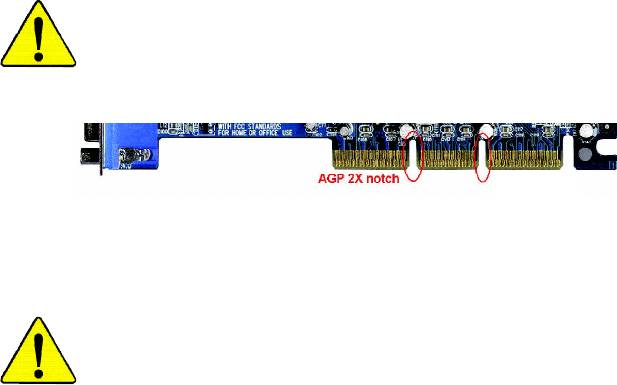
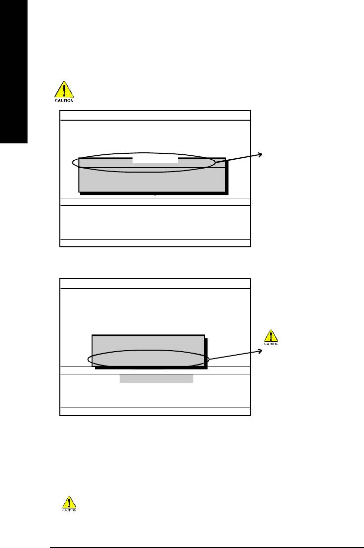
When you installing AGP card, please make sure the following
notice is fully understood and practiced. If your AGP card has
"AGP 4X/8X (1.5V) notch"(show below), please make sure your
AGP card is AGP 4X/8X (1.5V).
AGP 4X/8X notch
®
Caution: AGP 2X card is not supported by Intel
845(GE/PE) / 845(E/
G) / 850(E) / E7205 / 865(G/PE/PL/P) / 875P / 848P. You might
experiencesystem unable to boot up normally. Please insert an AGP
4X/8X card.
Example 1: Diamond Vipper V770 golden finger is compatible with 2X/4X
mode AGP slot. It can be switched between AGP 2X(3.3V) or 4X(1.5V)
mode by adjusting the jumper. The factory default for this card is
2X(3.3V). The GA-8I865P(-G) (or any AGP 4X/8X only) motherboards
might not function properly, if you install this card without switching the
jumper to 4X(1.5V) mode in it.
Example 2: Some ATi Rage 128 Pro graphics cards made by "Power Color",
the graphics card manufacturer & some SiS 305 cards, their golden finger
is compatible with 2X(3.3V)/4X(1.5V) mode AGP slot, but they support 2X
(3.3V) only. The GA-8I865P(-G) (or any AGP 4X/8X only) motherboards
might not function properly, If you install this card in it.
Note: Although Gigabyte's AG32S(G) graphics card is based on ATi Rage
128 Pro chip, the design of AG32S(G) is compliance with AGP 4X(1.5V)
®
specification. Therefore, AG32S(G) will work fine with Intel
845(GE/PE) /
845(E/G) / 850(E) / E7205 / 865(G/PE/PL/P) / 875P / 848P based
motherboards.
M The author assumes no responsibility for any errors
or omissions that may appear in this document nor
does the author make a commitment to update the
information contained herein.
M Third-party brands and names are the property of
their respective owners.
M Please do not remove any labels on motherboard, this
may void the warranty of this motherboard.
M Due to rapid change in technology, some of the
specifications might be out of date before publication
of this booklet.

Mother Board
GA-8I865P-G/GA-8I865P
Jun. 04, 2004

DECLARATION OF CONFORMITY
Per FCC Part 2 Section 2.1077(a)
Responsible Party Name:
G.B.T. INC. (U.S.A.)
Address:
17358 Railroad Street
City of Industry, CA 91748
Phone/Fax No:
(818) 854-9338/ (818) 854-9339
hereby declares that the product
Product Name:
Motherboard
Model Number:
GA-8I865P-G/GA-8I865P
Conforms to the following specifications:
FCC Part 15, Subpart B, Section 15.107(a) and Section 15.109
(a),Class B Digital Device
Supplementary Information:
This device complies with part 15 of the FCC Rules. Operation is
subject to the following two conditions: (1) This device may not
cause harmful and (2) this device must accept any inference received,
including that may cause undesired operation.
Representative Person’s Name:
ERIC LU
Signature:
Eric Lu
Date:
Jun. 04, 2004
GA-8I865P(-G)
P4 Titan Series Motherboard
USER'S MANUAL
®
Pentium
4 Processor Motherboard
Rev. 1001
12ME-8I865PG-1001

Table of Content
English
Warning ..............................................................................................4
Chapter 1 Introduction .........................................................................5
Features Summary .......................................................................................... 5
GA-8I865P(-G) Motherboard Layout .............................................................. 7
Block Diagram .................................................................................................. 8
Chapter 2 Hardware Installation Process ............................................ 11
Step 1: Install the Central Processing Unit (CPU) ....................................... 12
Step 1-1: CPU Installation ........................................................................................... 12
Step 1-2 : CPU Cooling Fan Installation ......................................................................13
Step 2: Install memory modules ................................................................... 14
Step 3: Install expansion cards ..................................................................... 17
Step 4: Install I/O Peripherals Cables .......................................................... 18
Step 4-1: I/O Back Panel Introduction ..........................................................................18
Step 4-2: Connectors & Jumper Setting Introduction .................................................... 20
Chapter 3 BIOS Setup ....................................................................... 31
The Main Menu (For example: BIOS Ver. : E3) ........................................... 32
Standard CMOS Features ............................................................................. 34
Advanced BIOS Features.............................................................................. 37
Integrated Peripherals .................................................................................. 38
Power Management Setup ............................................................................ 42
- 2 -GA-8I865P(-G) Motherboard

English
PnP/PCI Configurations................................................................................. 44
PC Health Status ........................................................................................... 45
Frequency/Voltage Control ............................................................................ 46
Load Fail-Safe Defaults ................................................................................. 49
Load Optimized Defaults ............................................................................... 49
Set Supervisor/User Password ..................................................................... 50
Save & Exit Setup .......................................................................................... 51
Exit Without Saving ...................................................................................... 51
Chapter 4 Technical Reference .......................................................... 53
Flash BIOS Method Introduction ................................................................... 53
2- / 4- / 6- / 8- Channel Audio Function Introduction .................................... 64
Jack-Sensing and UAJ Introduction ............................................................. 70
Xpress Recovery Introduction ....................................................................... 72
Chapter 5 Appendix .......................................................................... 75
- 3 -
Table of Content

Warning
English
Computer motherboards and expansion cards contain very delicate Integrated Circuit (IC) chips. To
protect them against damage from static electricity, you should follow some precautions whenever you
work on your computer.
1. Unplug your computer when working on the inside.
2. Use a grounded wrist strap before handling computer components. If you do not have
one, touch both of your hands to a safely grounded object or to a metal object, such as
the power supply case.
3. Hold components by the edges and try not touch the IC chips, leads or connectors, or
other components.
4. Place components on a grounded antistatic pad or on the bag that came with the
components whenever the components are separated from the system.
5. Ensure that the ATX power supply is switched off before you plug in or remove the ATX
power connector on the motherboard.
Installing the motherboard to the chassis…
If the motherboard has mounting holes, but they don't line up with the holes on the base and there
are no slots to attach the spacers, do not become alarmed you can still attach the spacers to the
mounting holes. Just cut the bottom portion of the spacers (the spacer may be a little hard to cut off, so
be careful of your hands). In this way you can still attach the motherboard to the base without worrying
about short circuits. Sometimes you may need to use the plastic springs to isolate the screw from the
motherboard PCB surface, because the circuit wire may be near by the hole. Be careful, don't let the
screw contact any printed circuit write or parts on the PCB that are near the fixing hole, otherwise it may
damage the board or cause board malfunctioning.
- 4 -GA-8I865P(-G) Motherboard

English
Chapter 1 Introduction
Features Summary
®
®
CPU — Socket 478 for Intel
Pentium
4 (Northwood, Prescott)
with HT Technology
®
®
(Note 1)
— Intel
Pentium
4 400/533/800
MHz FSB
— 2nd cache depends on CPU
®
Chipset — North Bridge: Intel
865P
®
— South Bridge: Intel
ICH5
Memory — 4 184-pin DDR DIMM sockets
(Note 2)
— Supports Dual channel DDR400
/DDR333/DDR266 DIMM
— Supports 128MB/256MB/512MB/1GB unbuffered DRAM
(Note 3)
— Supports up to 4GB DRAM (Max)
Slots — 1 AGP slot supports 8X/4X(1.5V) mode
— 5 PCI slots
On-Board IDE — 2 IDE bus master (UDMA33/ATA66/ATA100) IDE ports for up
to 4 ATAPI devices
— Can connect up to 4 IDE devices
On-Board Floppy — 1 Floppy port supports 2 FDD with 360K, 720K,1.2M, 1.44M
and 2.88M bytes
On-Board Peripherals — 1 Parallel port supports Normal/EPP/ECP mode
— 2 Serial ports (COMA & COMB)
— 8 USB 2.0/1.1 ports (4 x Rear, 4 x Front by cable)
— 1 IrDA connector for IR/CIR
— 1 Front Audio connector
— 1 PS/2 keyboard
— 1 PS/2 mouse
to be continued......
Due to chipset (Intel 865P) architecture limitation, a FSB 533 Pentium 4 processor will support
DDR333 and DDR266 mem ory module. A FSB 400 Pentium 4 processor will only support DDR
266 memory module.
(Note 1) An FSB800 CPU can be supported through overclocking in BIOS.
(Note 2) When FSB800 is selected as CPU frequency, memory will automatically adjust to DDR400.
(Note 3) Due to standard PC architecture, a certain amount of memory is reserved for system
usage and therefore the actual memory size is less than the stated amount.
For example, 4 GB of memory size will instead be shown as 3.xxGB memory during
system startup.
Introduction- 5 -

(
)
On-Board LAN
*
— Build in Marvell 8001 Chipset (10/100/1000 Mbit)
— 1 RJ45 port
On-Board Sound — ALC850 CODEC (UAJ)
— Supports Jack Sensing function
English
— Supports 2 / 4 / 6 / 8 channel audio
— Supports Line In / Line Out / MIC connection
— Surround Back Speaker (use of Surround-Kit to select)
— SPDIF In / Out
— CD In / Game connector
Serial ATA — 2 Serial ATA connectors (SATA0/SATA1)
— Controlled by ICH5
Hardware Monitor — CPU/System Fan Revolution detect
— CPU/System Fan Fail Warning
— CPU Overheat Warning
— System Voltage Detect
I/O Control — IT8712
PS/2 Connector — PS/2 Keyboard interface and PS/2 Mouse interface
BIOS — Licensed AWARD BIOS
— Supports Q-Flash
Additional Features — Supports EasyTune
— Supports @BIOS
Overclocking — Over Voltage (DDR/AGP/CPU) by BIOS
— Over Clock (DDR/AGP/CPU/PCI) by BIOS
Form Factor — ATX size form factor; 30.5cm x 23.0cm
(*) Only for GA-8I865P-G.
- 6 -GA-8I865P(-G) Motherboard
English
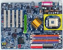
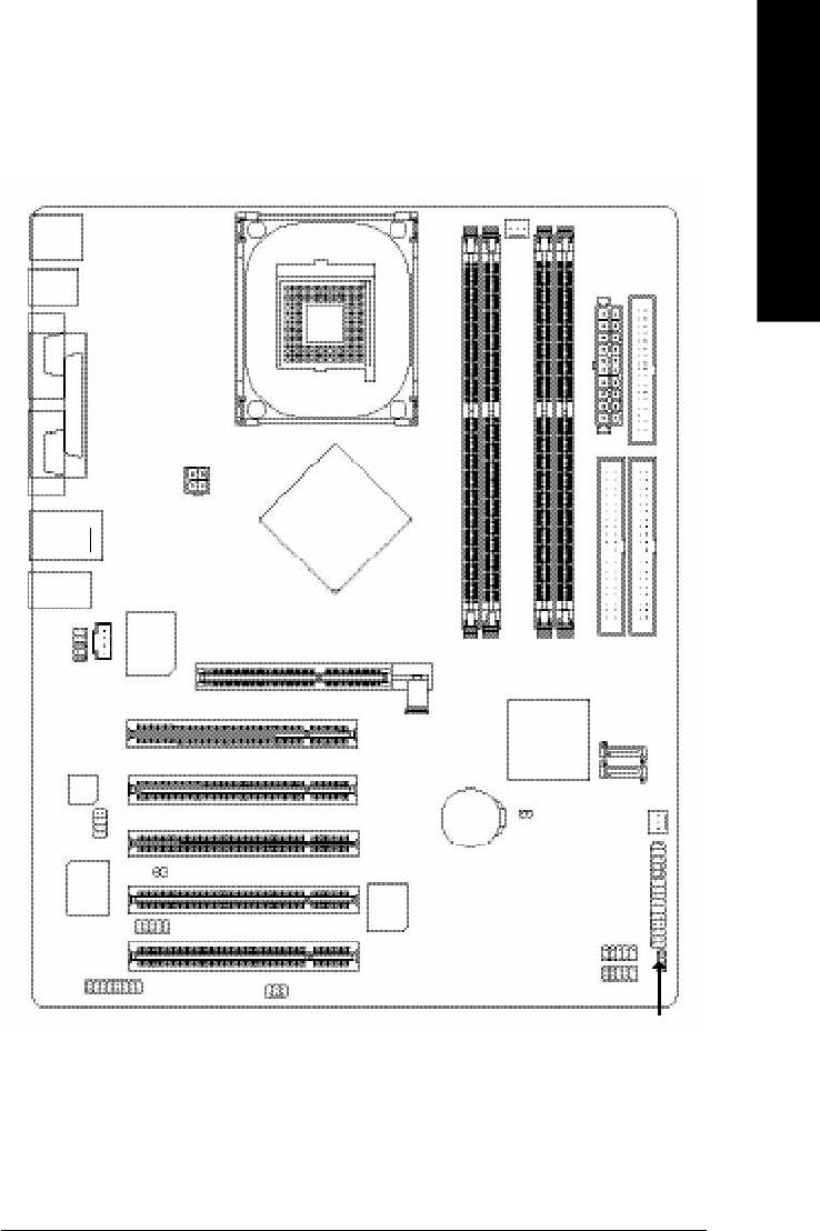
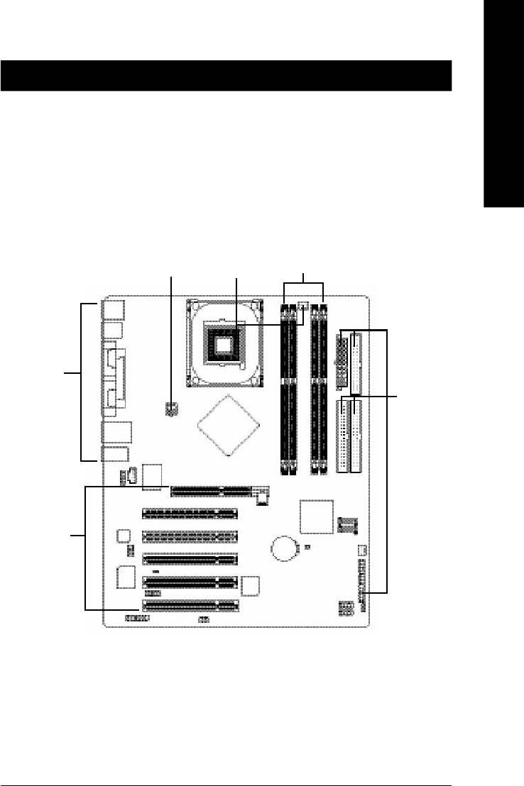
GA-8I865P(-G) Motherboard Layout
KB_M S
R_USB
CPU_FAN
ATX
FDD
COMA
SOC KET4 78
Hyper Threading
LPT
ATX_ 12 V
COMB
)
(
*
USB
LAN
GA-8I865P(-G)
MIC_IN
LINE_OUT
LINE_IN
CD_IN
®
Intel
865P
Marv ell
DDR1
DDR2
(
)
8 0 0 1
*
AGP
IDE2
IDE1
DDR3
DDR4
F_AUDIO
ICH5
SATA1
PCI1
P4 Titan
CODEC
SATA0
CLR_CMOS
PCI2
SUR_C EN
BAT
SYS_FAN
INFO_LINK
PCI3
CI
F_PAN EL
IT8712
BIOS
PCI4
IR_CIR
F_U SB2
F_U SB1
PCI5
GAM E
SPDIF_IO
PWR_LED
(*) Only for GA-8I865P-G.
Introduction- 7 -
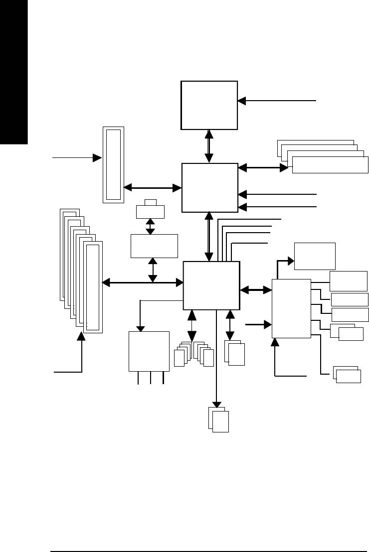
Block Diagram
English
Pentium 4
CPUCLK+/- (100/133/200MHz)
Socket 478
CPU
AGP 8X/4X
AGPCLK
System Bus
(66MHz)
400/533/800MHz
DDR
266/333/400MHz
Intel 865P
ZCLK (66MHz)
5 PCI
HCLK+/- (100/133/200MHz)
(
)
RJ45
*
66MHz
33 MHz
14.318 MHz
48 MHz
(
)
Marvell 8001
*
BIOS
ICH5
Game Port
LPC BUS
Floppy
IT8712
AC97 Link
24 MHz
LPT Port
AC97
PS/2
PCICLK
CODEC
KB/Mouse
(33MHz)
ATA33/66/100
33 MHz
8 USB
IDE Channels
(2.0/1.1)
COM
MIC
Ports
Ports
LINE-IN
LINE-OUT
Serial ATA
Channels
(*) Only for GA-8I865P-G.
- 8 -GA-8I865P(-G) Motherboard

English
Introduction- 9 -

English
- 10 -GA-8I865P(-G) Motherboard
English
Chapter 2 Hardware Installation Process
To set up your computer, you must complete the following steps:
Step 1- Install the Central Processing Unit (CPU)
Step 2- Install memory modules
Step 3- Install expansion cards
Step 4- Install I/O Peripherals Cables
Step 2
Step 4
Step 1
Step 4
Step 4
Step 3
Congratulations you have accomplished the hardware installation!
Turn on the power supply or connect the power cable to the power outlet. Continue with the BIOS/
software installation.
- 11 - Hardware Installation Process
Step 1: Install the Central Processing Unit (CPU)
Before installing the processor, adhere to the following warning:
1. Please make sure that the motherboard supports the CPU.
2. Please take note of the one indented corner of the CPU. If you install the CPU in the wrong
English
direction, the CPU will not insert properly. If this occurs, please change the insert direction of
the CPU.
3. Please add an even layer of heat sink paste between the CPU and heatsink.
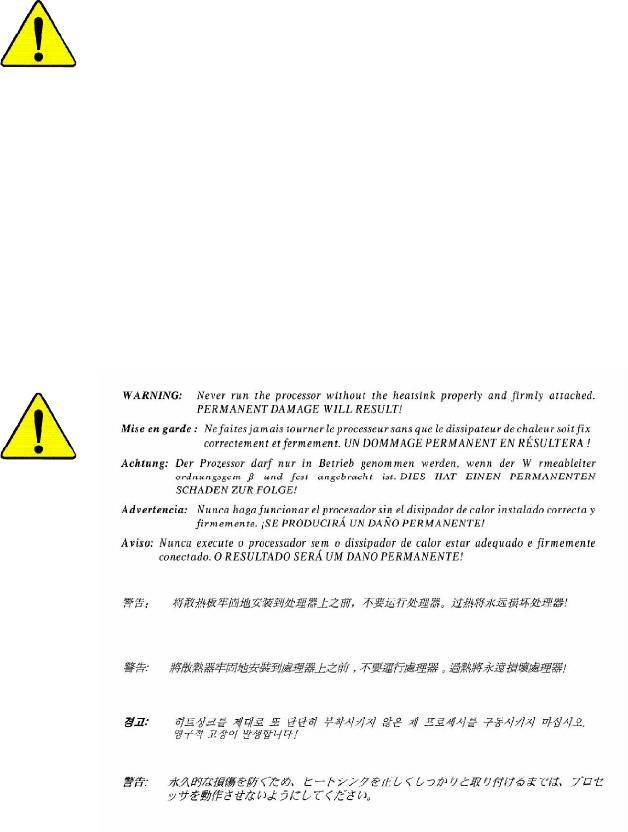
4. Please make sure the heatsink is installed on the CPU prior to system use, otherwise
overheating and permanent damage of the CPU may occur.
5. Please set the CPU host frequency in accordance with the processor specifications. It is not
recommended that the system bus frequency be set beyond hardware specifications since
it does not meet the required standards for the peripherals. If you wish to set the frequency
beyond the proper specifications, please do so according to your hardware specifications
including the CPU, graphics card, memory, hard drive, etc.
HT functionality requirement content :
Enabling the functionality of Hyper-Threading Technology for your computer system requires all
of the following platform components:
®
®
- CPU: An Intel
Pentium
4 Processor with HT Technology
®
- Chipset: An Intel
Chipset that supports HT Technology
- BIOS: A BIOS that supports HT Technology and has it enabled
- OS: An operation system that has optimizations for HT Technology
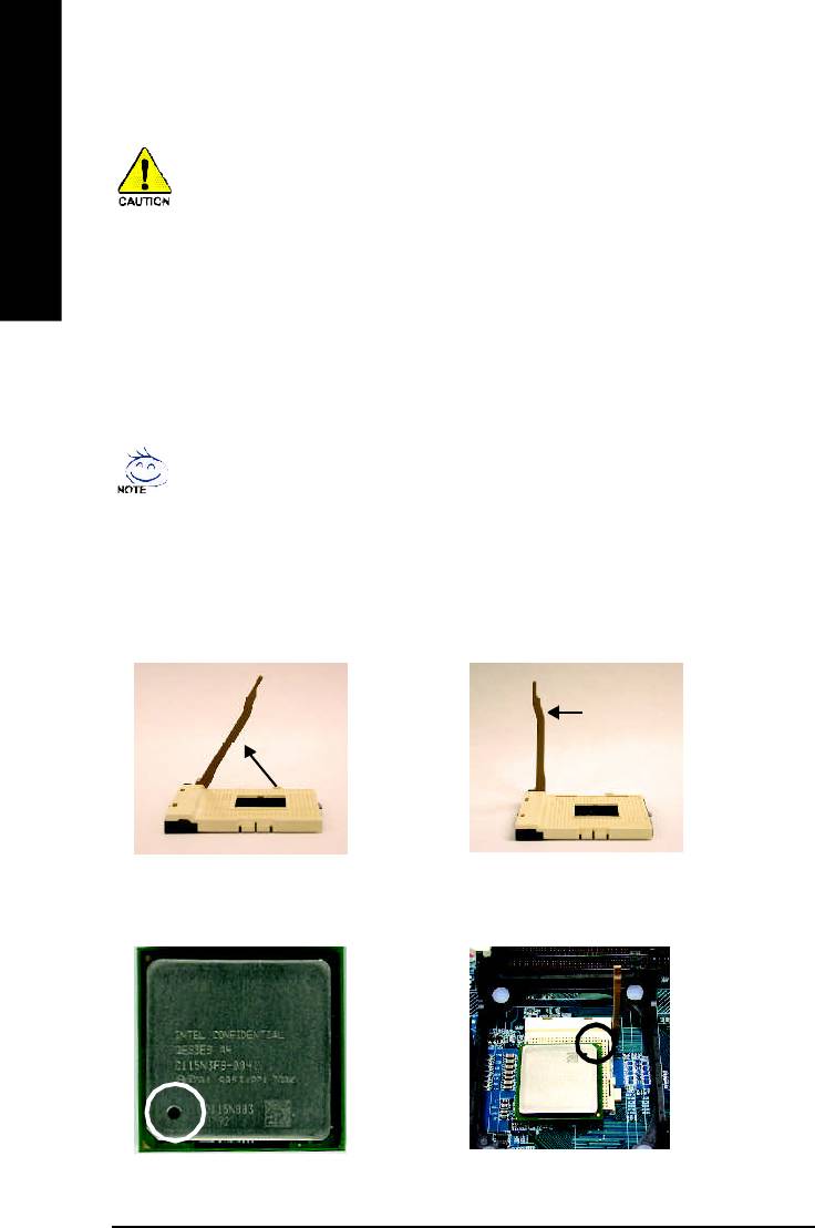
Step 1-1: CPU Installation
Socket
Angling the
Actuation
0
r o d t o 6 5
Lever
1. Angling the rod to 65-degree maybe feel a
2. Pull the rod to the 90-degree directly.
kind of tight, and then continue pull the rod
to 90-degree when "click" noise is heard.
Pin1 indicator
Pin1 indicator
4. Locate Pin 1 in the socket and look for a (golden)
3. CPU Top View
cut edge on the CPU upper corner. Then insert
the CPU into the socket.
- 12 -GA-8I865P(-G) Motherboard
English
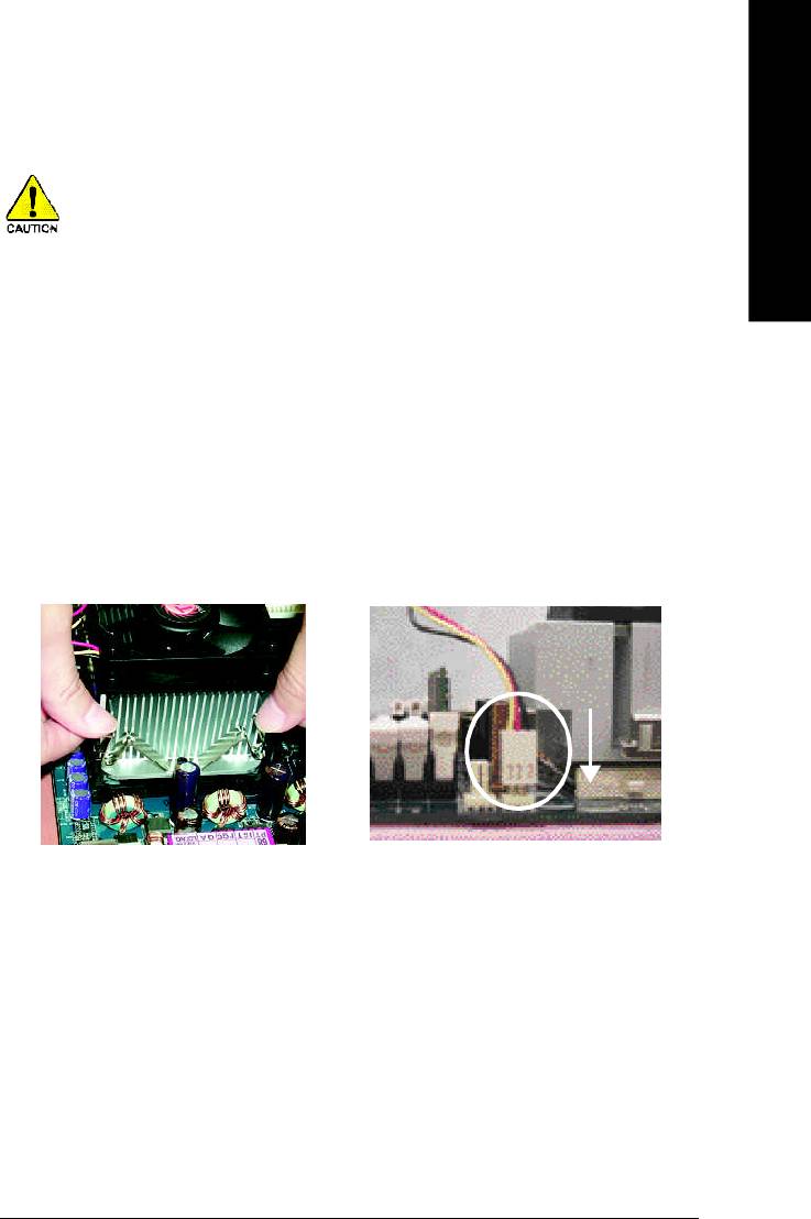
Step 1-2 : CPU Cooling Fan Installation
Before installing the CPU cooling fan, adhere to the following warning:
1. Please use Intel approved cooling fan.
2. We recommend you to apply the thermal tape to provide better heat conduction
between your CPU and cooling fan.
(The CPU cooling fan might stick to the CPU due to the hardening of the thermal
paste. During this condition if you try to remove the cooling fan, you might pull the
processor out of the CPU socket alone with the cooling fan, and might damage the
processor. To avoid this from happening, we suggest you to either use thermal tape
instead of thermal paste, or remove the cooling fan with extreme caution.)
3. Make sure the CPU fan power cable is plugged in to the CPU fan connector, this
completes the installation.
Please refer to CPU cooling fan user's manual for more detail installation procedure.
2. Make sure the CPU fan is plugged to
1. Fasten the cooling fan supporting-base
the CPU fan connector, than install
onto the CPU socket on the
complete.
mainboard.
- 13 - Hardware Installation Process
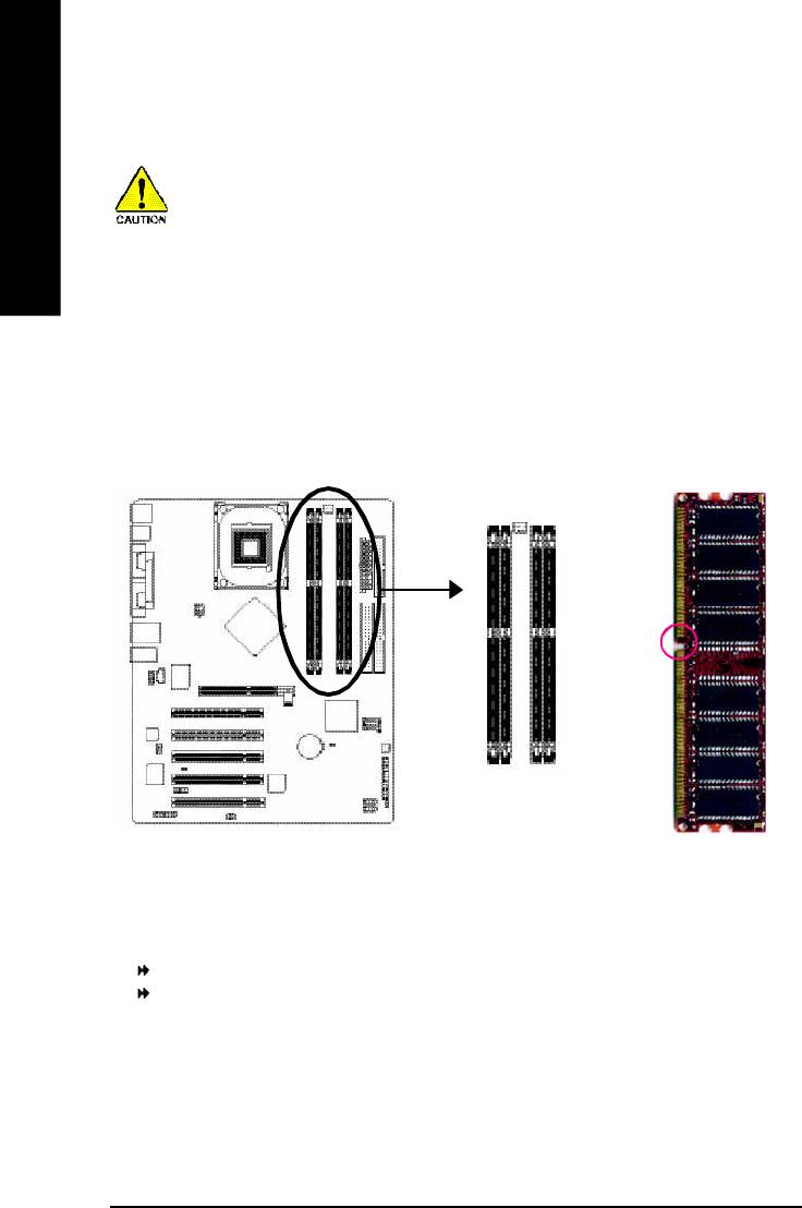
Step 2: Install memory modules
Before installing the memory modules, please comply with the following conditions:
1. Please make sure that the memory used is supported by the motherboard. It is
English
recommended that memory of similar capacity, specifications and brand be used.
2. Before installing or removing memory modules, please make sure that the computer
power is switched off to prevent hardware damage.
3. Memory modules have a foolproof insertion design. A memory module can be in-
stalled in only one direction. If you are unable to insert the module, please switch
the direction.
The motherboard supports DDR memory modules, whereby BIOS will automatically detect memory
capacity and specifications. Memory modules are designed so that they can be inserted only in
one direction. The memory capacity used can differ with each slot.
Notch
DDR
GA-8I865P(-G) supports the Dual Channel Technology. After operating the Dual Channel Technology,
the bandwidth of Memory Bus will add double up to 6.4GB/s.
GA-8I865P(-G) includes 4 DIMM sockets, and each Channel has two DIMM sockets as following:
Channel A : DIMM 1, DIMM 2
Channel B : DIMM 3, DIMM 4
If you want to operate the Dual Channel Technology, please note the following explanations due to
®
the limitation of Intel
chipset specifications.
1. Only one DDR memory module is installed: The Dual Channel Technology can't operate
when only one DDR memory module is installed.
- 14 -GA-8I865P(-G) Motherboard

English
2. Two DDR memory modules are installed (the same memory size and type): The Dual
Channel Technology will operate when two memory modules are inserted individually into
Channel A and B. If you install two memory modules in the same channel, the Dual Channel
Technology will not operate.
3. Three DDR memory modules are installed: Please note that The Dual Channel
Technology will not operate when three DDR memory modules are installed; part of
them will not be detected.
4. Four DDR memory modules are installed: If you install four memory modules at the same
time, the Dual Channel Technology will operate only when those modules have the same
memory size and type.
We'll strongly recommend our user to slot two DDR memory modules into the DIMMs with the
same color in order for Dual Channel Technology to work.
The following tables include all memory-installed combination types:
(Please note that those types not in the tables will not boot up.)
l Figure 1: Dual Channel Technology (DS: Double Side, SS: Single Side)
DIMM 1 DIMM 2 DIMM 3 DIMM 4
2 memory modules
DS/SS X DS/SS X
X DS/SS X DS/SS
4 memory modules
DS/SS DS/SS DS/SS DS/SS
l Figure 2: Don't operate Dual Channel Technology (DS: Double Side, SS: Single Side)
DIMM 1 DIMM 2 DIMM 3 DIMM 4
1 memory module
DS/SS X X X
X DS/SS X X
X X DS/SS X
X X X DS/SS
2 memory modules
DS/SS DS/SS X X
X X DS/SS DS/SS
3 memory modules
DS/SS DS/SS DS/SS X
DS/SS DS/SS X DS/SS
DS/SS X DS/SS DS/SS
X DS/SS DS/SS DS/SS
- 15 - Hardware Installation Process
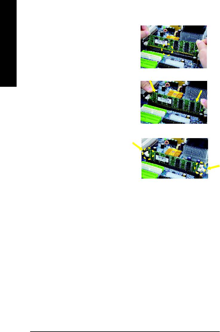
1. The DIMM slot has a notch, so the DIMM
memory module can only fit in one direction.
English
2. Insert the DIMM memory module vertically into
the DIMM slot. Then push it down.
3. Close the plastic clip at both edges of the DIMM
slots to lock the DIMM module.
Reverse the installation steps when you wish
to remove the DIMM module.
DDR Introduction
Established on the existing SDRAM infrastructure, DDR (Double Data Rate) memory is a high
performance and cost-effective solution that allows easy adoption for memory vendors, OEMs,
and system integrators.
DDR memory is a great evolutionary solution for the PC industry that builds on the existing
SDRAM architecture, yet make the awesome advances in solving the system performance
bottleneck by doubling the memory bandwidth. Nowadays, with the highest bandwidth of 3.2GB/
s of DDR400 memory and complete line of DDR400/333/266/200 memory solutions, DDR memory
is the best choice for building high performance and low latency DRAM subsystem that are
suitable for servers, workstations, and full range of desktop PCs.
- 16 -GA-8I865P(-G) Motherboard
English
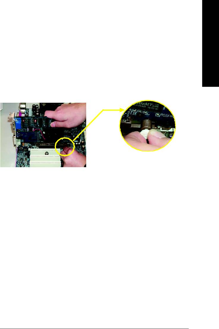
Step 3: Install expansion cards
1. Read the related expansion card's instruction document before install the expansion card into
the computer.
2. Remove your computer’s chassis cover, necessary screws and slot bracket from the computer.
3. Press the expansion card firmly into expansion slot in motherboard.
4. Be sure the metal contacts on the card are indeed seated in the slot.
5. Replace the screw to secure the slot bracket of the expansion card.
6. Replace your computer's chassis cover.
7. Power on the computer, if necessary, setup BIOS utility of expansion card from BIOS.
8. Install related driver from the operating system.
Please carefully pull out the small white- drawable bar
at the end of the AGP slot when you try to install/
Uninstall the AGP card. Please align the AGP card to
AGP Card
the onboard AGP slot and press firmly down on the slot
.Make sure your AGP card is locked by the small white-
drawable bar.
- 17 - Hardware Installation Process
Step 4: Install I/O Peripherals Cables
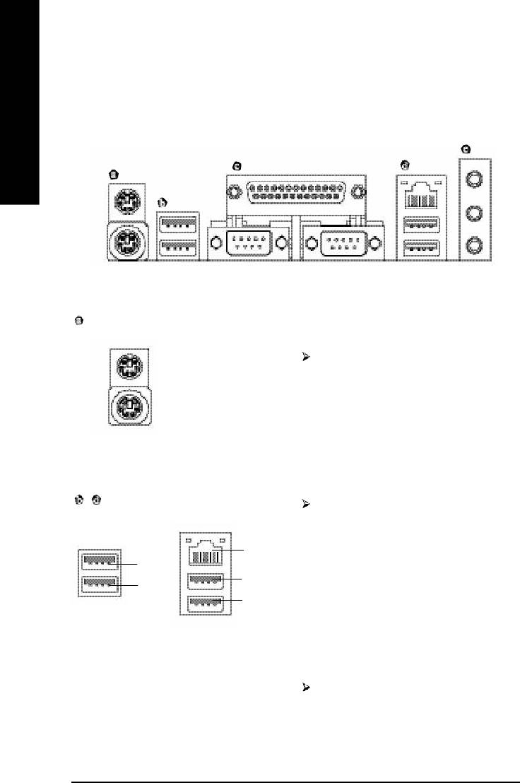
Step 4-1: I/O Back Panel Introduction
English
PS/2 Keyboard and PS/2 Mouse Connector
PS/2 Mouse Connector
This connector supports standard PS/2
(6 pin Female)
keyboard and PS/2 mouse.
PS/2 Keyboard Connector
(6 pin Female)
(
)
/ USB / LAN
*
Connector
Before you connect your device(s) into USB
connector(s), please make sure your
device(s) such as USB keyboard,mouse,
(
)
LAN
*
scanner, zip, speaker..etc. Have a standard
USB 3
USB interface. Also make sure your OS
USB 5
USB 2
supports USB controller.
USB 4
If your OS does not support USB controller,
please contact OS vendor for possible patch
or driver upgrade. For more information
please contact your OS or device(s) vendors.
LAN connector is fast Ethernet with 10/100/
1000 Mbps speed.
(*) Only for GA-8I865P-G.
- 18 -GA-8I865P(-G) Motherboard

English
Parallel Port and Serial Ports (COMA/COMB)
Parallel Port
This connector supports 2 standard
(25 pin Female)
COM ports and 1 Parallel port. Device like
printer can be connected to Parallel port;
mouse and modem etc can be connected to
Serial ports.
COMA
COMB
Serial Port (9 pin Male)
Audio Connectors
After install onboard audio driver, you may
connect speaker to Line Out jack,
microphone to MIC In jack. Devices like
Line In
CD-ROM, walkman etc. can be connected
to Line-In jack.
Line Out
Please note:
MIC In
You are able to use 2-/4-/6-/8-channel audio
feature by S/W selection.
If you want to enable 8-channel function you
can refer to page 25, and contact your
nearest dealer for optional SUR_CEN cable.
If you want the detail information for 2-/ 4-/ 6-/ 8-channel audio setup
installation, please refer to page 64.
- 19 - Hardware Installation Process
Step 4-2: Connectors & Jumper Setting Introduction
1 3
English
5
2
6
12
10
7
11
4
17
18
9
14
8
16
13
20
19
15
1) ATX_12V 11) SUR_CEN
2) ATX 12) CD_IN
3) CPU_FAN 13) SPDIF_IO
4) SYS_FAN 14) IR_CIR
5) FDD 15) F_USB1/F_USB2
6) IDE1/IDE2 16) GAME
7) SATA0/SATA1 17) INFO_LINK
8) PWR_LED 18) CI
9) F_PANEL 19) CLR_CMOS
10) F_AUDIO 20) BAT
- 20 -GA-8I865P(-G) Motherboard
English
1/2) ATX_12V/ATX (Power Connector)
With the use of the power connector, the power supply can supply enough stable power to all the
components on the motherboard. Before connecting the power connector, please make sure that all
components and devices are properly installed. Align the power connector with its proper location on
the motherboard and connect tightly.
The ATX_12V power connector mainly supplies power to the CPU. If the ATX_12V power
connector is not connected, the system will not start.
Caution!
Please use a power supply that is able to handle the system voltage requirements. It is
recommended that a power supply that can withstand high power consumption be used (300W or
greater). If a power supply is used that does not provide the required power, the result can lead to an
unstable system or a system that is unable to start.
Pin No. Definition
1 GND
2
1
2 GND
3 +12V
4
3
4 +12V
Pin No. Definition
1 3.3V
2 3.3V
3 GND
4 VCC
5 GND
11
1
6 VCC
7 GND
8 Power Good
9 5V SB(stan d b y +5 V)
10 +12V
11 3.3V
12 -12V
13 GND
14 PS_ON(softOn/Off)
15 GND
16 GND
20
10
17 GND
18 -5V
19 VCC
20 VCC
- 21 - Hardware Installation Process
3/4) CPU_FAN / SYS_FAN (Cooler Fan Power Connector)
The cooler fan power connector supplies a +12V power voltage via a 3-pin power connector and
possesses a ful-proof connection design.
Most coolers are designed with color-coded power connector wires. A red power connector wire
English
indicates a positive connection and requires a +12V power voltage. The black connector wire is the
ground wire (GND).
Please remem ber to connect the power to the cooler to prevent system overheating and failure.
Caution!
Please remember to connect the power to the CPU fan to prevent CPU overheating and failure.
1
Pin No. Definition
CPU_FAN
1 GND
2 +12V
3 Sense
1
SYS_FAN
5) FDD (Floppy Connector)
The FDD connector is used to connect the FDD cable while the other end of the cable connects to the
FDD drive. The types of FDD drives supported are: 360KB, 720KB, 1.2MB, 1.44MB and 2.88MB.
Please connect the red power connector wire to the pin1 position.
34
33
2
1
- 22 -GA-8I865P(-G) Motherboard
English
6) IDE1/ IDE2(IDE1/IDE2 Connector)
Each IDE connector can connect with one IDE cable to connect the IDE hard drive with the computer.
It is recom mended that the first hard drive be connected to the IDE1 connector while the disk drive be
connected to the IDE2 connector.
40
39
2
1
IDE2
IDE1
7) SATA0/SATA1 (Serial ATA Connector)
You can connect the Serial ATA device to this connector.
Pin No. Definition
1 GND
2 TXP
3 TXN
4 GND
7
1
5 RXN
6 RXP
7 GND
- 23 - Hardware Installation Process
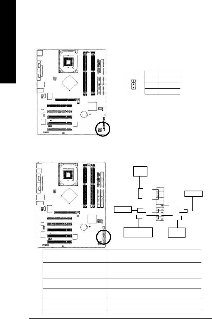
8) PWR_LED
PWR_LED is connect with the system power indicator to indicate whether the system is on/off. It will blink
when the system enters suspend mode. If you use dual color LED, power LED will turn to another color.
English
Pin No. Definition
1 MPD+
2 MPD-
1
3 MPD-
9) F_PANEL (2x10 pins connector)
Please connect the power LED, PC peaker, reset switch and power switch etc of your chassis front panel
to the F_PANEL connector according to the pin assignment below.
Speaker
Connector
20
19
SPEAK-
Reset Switch
SPEAK+
NC
Power Switch
PW-
RES+
PW+
RES-
MSG-
HD-
MSG+
HD+
2
1
Message LED/Power/
IDE Hard Disk
Sleep LED
Active LED
HD (IDE Hard Disk Active LED) Pin 1: LED anode(+)
(Blue) Pin 2: LED cathode(-)
SPEAK (Speaker Connector) Pin 1: VCC(+)
(Amber) Pin 2- Pin 3: NC
Pin 4: Data(-)
RES (Reset Switch) Open: Normal Operation
(Green) Close: Reset Hardware System
PW (Power Switch) (Red) Open: Normal Operation
Close: Power On/Off
MSG (Message LED/Power/ Pin 1: LED anode(+)
Sleep LED)(Yellow) Pin 2: LED cathode(-)
NC (Purple) NC
- 24 -GA-8I865P(-G) Motherboard
English
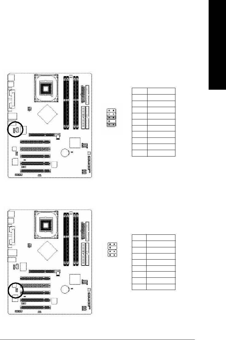
10) F_AUDIO (F_AUDIO Connector)
If you want to use Front Audio connector, you must remove 5-6, 9-10 Jumper. In order to utilize the
front audio header, your chassis must have front audio connector. Also please make sure the pin
assigment on the cable is the same as the pin assigment on the MB header. To find out if the chassis
you are buying support front audio connector, please contact your dealer.Please note, you can have the
alternative of using front audio connector or of using rear audio connector to play sound.
Pin No. Definition
1 MIC
2 GND
3 MIC_BIAS
1 2
4 POWER
5 FrontAudio(R)
109
6 RearAudio(R)
7 Reserved
8 No Pin
9 FrontAudio (L)
10 RearAudio(L)
11) SUR_CEN
Please contact your nearest dealer for optional SUR_CEN cable.
Pin No. Definition
1
2
1 SUR OUTL
2 SUR OUTR
7 8
3 GND
4 No Pin
5 CENTER_OUT
6 BASS_OUT
7 AUX_L
8 AUX_R
- 25 - Hardware Installation Process
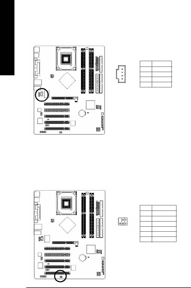
12) CD_IN (CD IN)
Connect CD-ROM or DVD-ROM audio out to the connector.
English
Pin No. Definition
1 CD-L
1
2 GND
3 GND
4 CD_R
13) SPDIF_IO (SPDIF In/Out)
The SPDIF output is capable of providing digital audio to external speakers or compressed AC3 data to
an external Dolby Digital Decoder. Use this feature only when your stereo system has digital input
function. Use SPDIF IN feature only when your device has digital output function.
Be careful with the polarity of the SPDIF_IO connector. Check the pin assignment carefully while you
connect the SPDIF cable, incorrect connection between the cable and connector will m ake the
device unable to work or even damage it. For optional SPDIF cable, please contact your local
dealer.
Pin No. Definition
1 VCC
62
2 No Pin
3 SPDIF
1
5
4 SPDIFI
5 GND
6 GND
- 26 -GA-8I865P(-G) Motherboard
English
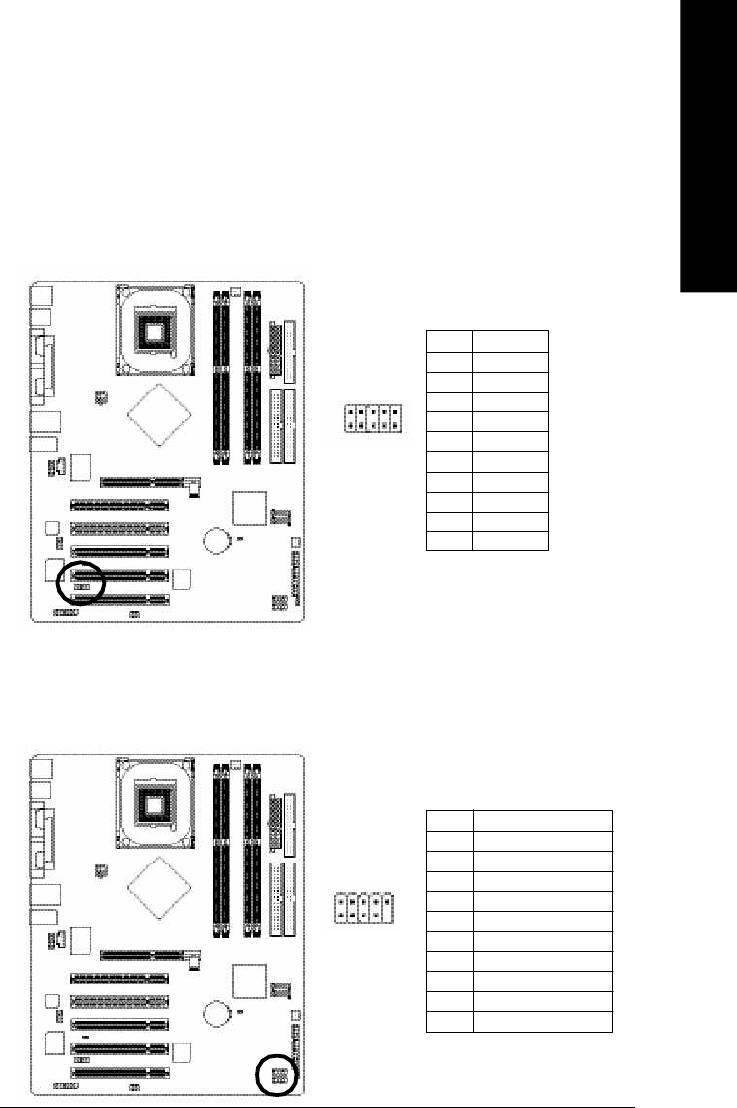
14) IR_CIR
Make sure the pin 1 on the IR device is aling with pin one the connector. To enable the IR/CIR function
on the board, you are required to purchase an option IR/CIR m odule. For detail inform ation please
contact your autherized Giga-Byte distributor. To use IR function only, please connect IR module to
Pin1 to Pin5.
Be careful with the polarity of the IR/CIR connector. Check the pin assignment carefully while you
connect the IR/CIR cable, incorrect connection between the cable and connector will make the device
unable to work or even damage it. For optional IR/CIR cable, please contact your local dealer.
Pin No. Definition
1 VCC
2 NC
6
10
3 IRRX
4 GND
5 IRTX
1
5
6 NC
7 CIRRX
8 VCC
9 CIRTX
10 NC
15) F_ USB1 / F_USB2(Front USB Connector)
Be careful with the polarity of the front USB connector. Check the pin assignment carefully while
you connect the front USB cable, incorrect connection between the cable and connector will make
the device unable to work or even damage it. For optional front USB cable, please contact your
local dealer.
Pin No. Definition
1 Power
2 Power
3 USB0 DX-/USB6 DX-
2
10
4 USB1 Dy-/USB7 Dy-
5 USB0 DX+/USB6 DX+
1 9
6 USB1 Dy+/USB7 Dy+
7 GND
8 GND
9 No Pin
10 NC
- 27 - Hardware Installation Process
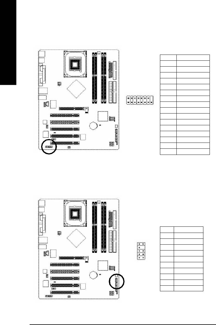
16) GAME (GAME Connector)
This connector supports joystick, MIDI keyboard and other relate audio devices.
English
Pin No. Definition
1 VCC
2 GRX1_R
3 GND
4 GPSA2
5 VCC
2
6 GPX2_R
16
7 GPY2_R
8 MSI_R
1 15
9 GPSA1
10 GND
11 GPY1_R
12 VCC
13 GPSB1
14 MSO_R
15 GPSB2
16 No Pin
17) INFO_LINK
This connector allows you to connect some external devices to provide you extra function.
Pin No. Definition
1 SMBCLK
2 VCC
10
9
3 SMBDATA
4 GPIO
2 1
5 GND
6 GND
7 No Pin
8 NC
9 +12V
10 +12V
- 28 -GA-8I865P(-G) Motherboard
English
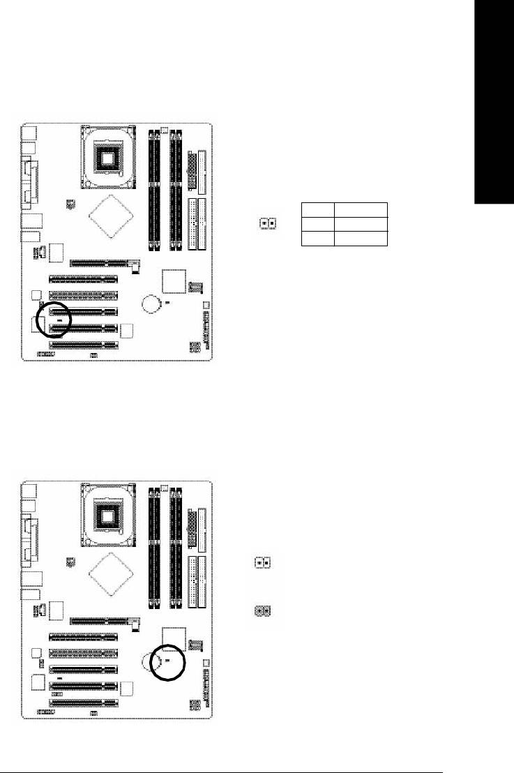
18) CI (Chassis Intrusion, Case Open)
This 2 pin connector allows your system to enable or disable the "case open" item in BIOS if the
system case begin remove.
Pin No. Definition
1
1 Signal
2 GND
19) CLR_CMOS (Clear CMOS)
You may clear the CMOS data to its default values by this jumper. To clear CMOS, temporarily
short 1-2 pin. Default doesn't include the "Shunter" to prevent from improper use this jumper.
1 Open: Normal
1
Short: Clear CMOS
- 29 - Hardware Installation Process
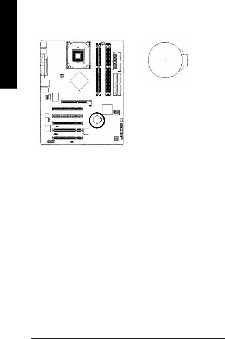
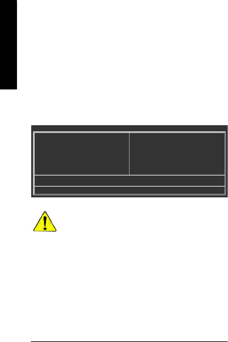
20) BAT (Battery)
English
CAUTION
v Danger of explosion if battery is incorrectly
replaced.
v Replace only with the same or equivalent
type recommended by the manufacturer.
v Dispose of used batteries according to the
manufacturer's instructions.
If you want to erase CMOS...
1.Turn OFF the computer and unplug the power
cord.
2.Remove the battery, wait for 30 second.
3.Re-install the battery.
4.Plug the power cord and turn ON the computer.
- 30 -GA-8I865P(-G) Motherboard

English
Chapter 3 BIOS Setup
BIOS (Basic Input and Output System) includes a CMOS SETUP utility which allows user to configure
required settings or to activate certain system features.
The CMOS SETUP saves the configuration in the CMOS SRAM of the motherboard.
When the power is turned off, the battery on the motherboard supplies the necessary power to the CMOS
SRAM.
When the power is turned on, pushing the <Del> button during the BIOS POST (Power-On Self Test) will
take you to the CMOS SETUP screen. You can enter the BIOS setup screen by pressing "Ctrl + F1".
When setting up BIOS for the first time, it is recommended that you save the current BIOS to a disk in the
event that BIOS needs to be reset to its original settings. If you wish to upgrade to a new BIOS, either
Gigabyte's Q-Flash or @BIOS utility can be used.
Q-Flash allows the user to quickly and easily update or backup BIOS without entering the operating
system.
@BIOS is a Windows-based utility that does not require users to boot to DOS before upgrading BIOS but
directly download and update BIOS from the Internet.
CONTROL KEYS
<á> Move to previous item
<â> Move to next item
<ß> Move to the item in the left hand
<à> Move to the item in the right hand
Enter Select item
<Esc> Main Menu - Quit and not save changes into CMOS Status Page Setup Menu and
Option Page Setup Menu - Exit current page and return to Main Menu
<+/PgUp> Increase the numeric value or make changes
<-/PgDn> Decrease the numeric value or make changes
<F1> General help, only for Status Page Setup Menu and Option Page Setup Menu
<F2> Item Help
<F3> Reserved
<F4> Reserved
<F5> Restore the previous CMOS value from CMOS, only for Option Page Setup Menu
<F6> Load the file-safe default CMOS value from BIOS default table
<F7> Load the Optimized Defaults
<F8> Q-Flash function
<F9> System Information
<F10> Save all the CMOS changes, only for Main Menu
- 31 - BIOS Setup
GETTING HELP
Main Menu
The on-line description of the highlighted setup function is displayed at the bottom of the screen.
English
Status Page Setup Menu / Option Page Setup Menu
Press F1 to pop up a small help window that describes the appropriate keys to use and the possible
selections for the highlighted item. To exit the Help Window press <Esc>.
The Main Menu (For example: BIOS Ver. : E3)
Once you enter Award BIOS CMOS Setup Utility, the Main Menu will appear on the screen. The Main
Menu allows y ou to select from eight setup functions and two exit choices. Use arrow keys to select
among the items and press <Enter> to accept or enter the sub-menu.
CMOS Setup Utility-Copyright (C) 1984-2004 Award Software
} Standard CMOS Features
Load Fail-Safe Defaults
} Advanced BIOS Features
Load Optimized Defaults
} Integrated Peripherals
Set Supervisor Password
} Power Management Setup
Set User Password
} PnP /PCI Configurations
Save & Exit Setup
} PC Health Status
Exit Without Saving
} Frequency/Voltage Control
ESC: Quit higf: Select Item
F8: Q-Flash F10: Save & Exit Setup
Time, Date, Hard Disk Ty pe...
If you can't find the setting you want, please press "Ctrl+F1" to
search the advanced option widden.
l Standard CMOS Features
This setup page includes all the items in standard compatible BIOS.
l Advanced BI OS Features
This setup page includes all the items of Award special enhanced features.
l Integrated Peripherals
This setup page includes all onboard peripherals.
- 32 -GA-8I865P(-G) Motherboard

English
l Power Management Setup
This setup page includes all the items of Green function features.
l PnP/PCI Configurations
This setup page includes all the configurations of PCI & PnP ISA resources.
l PC Health Status
This setup page is the System auto detect Temperature, voltage, fan, speed.
l Frequency/Voltage Control
This setup page is control CPU's clock and frequency ratio.
l Load Fail-Safe Defaults
Fail-Safe Defaults indicates the value of the system parameters which the system would
be in safe configuration.
l Load Optimized Defaults
Optimized Defaults indicates the value of the system parameters which the system would
be in best performance configuration.
l Set Supervisor password
Change, set, or disable password. It allows you to limit access to the system and Setup,
or just to Setup.
l Set User password
Change, set, or disable password. It allows you to limit access to the system.
l Save & Exit Setup
Save CMOS value settings to CMOS and exit setup.
l Exit Without Saving
Abandon all CMOS value changes and exit setup.
- 33 - BIOS Setup

Standard CMOS Features
CMOS Setup Utility-Copyright (C) 1984-2004 Award Software
Standard CMOS Features
Date (mm:dd:yy) Fri, May 15 2004
Item Help
English
Time (hh:mm :ss) 22:31:24
Menu Level}
} IDE Channel 0 Master [None]
Change the day, month,
} IDE Channel 0 Slave [None]
year
} IDE Channel 1 Master [None]
} IDE Channel 1 Slave [None]
<Week>
Sun. to Sat.
Drive A [1.44M, 3.5"]
Drive B [None]
<Month>
Floppy 3 Mode Suport [Disabled]
Jan. to Dec.
Holt On [All, But Keyboard]
<Day>
1 to 31 (or maximum
Base Memory 640K
allowed in the m onth)
Extended Memory 127M
Total Memory 128M
<Year>
1999 to 2098
higf: Move Enter: Select +/-/PU/P D: Value F10: Save ESC: Exit F1: General Help
F5: P revious Values F6: Fail-Save Default F7: Optimized Defaults
Date
The date format is <week>, <month>, <day>, <year>.
Week The w eek, from Sun to Sat, determined by the BIOS and is display only
Month The month, Jan. Through Dec.
Day The day, from 1 to 31 (or the maximum allowed in the month)
Year The year, from 1999 through 2098
Time
The times format in <hour> <minute> <second>. The time is calculated base on the 24-hour
military-time clock. For ex ample, 1 p.m. is 13:00:00.
- 34 -GA-8I865P(-G) Motherboard

English
IDE Channel 0 Master, Slave / IDE Channel 1 Master, Slave
IDE HDD Auto-Detection Press "Enter" to select this option for automatic device detection.
IDE Channel 0 Master(Slave) / IDE Channel 1 Master(Slave) IDE Device Setup. You can use
one of three methods:
Auto Allow s BIOS to automatically detect IDE devices during POST(default)
None Select this if no IDE devices are used and the system will skip the automatic
detec tion ste p and allow for faster system start up.
Manual User can manually input the correct settings
Access Mode Use this to set the access mode for the hard drive. The four options are:
CHS/LB A/Large/Auto(default:Auto)
Hard d rive information should be labeled on the outside driv e casing. Enter the appropriate option
based on this information.
Cylinder Number of cylinders
Head Number of heads
Precomp Write precomp
Landing Zone Landing zone
Sector Number of sectors
If a hard disk has not been installed, select NONE and press <Enter>.
Drive A / Drive B
The category identifies the types of floppy disk drive A or drive B that has been installed in the
computer.
None No fl oppy drive installed
360K, 5.25" 5.25 inch PC-type standard driv e; 360K by te capacity.
1.2M, 5.25" 5.25 inch AT-type high-density drive; 1.2M byte cap acity
(3.5 inch when 3 Mode is Enabled).
720K, 3.5" 3.5 inch double-sided drive; 720K byte capacity
1.44M, 3.5" 3.5 inch double-sided drive; 1.44M byte capa city.
2.88M, 3.5" 3.5 inch double-sided drive; 2.88M byte capa city.
- 35 - BIOS Setup

Floppy 3 Mode Support (for Japan Area)
Disa bled Normal Floppy Drive. (Default v alue)
Driv e A Drive A is 3 mode Floppy Drive.
English
Driv e B Drive B is 3 mode Floppy Drive.
Both Driv e A & B are 3 mode Floppy Drives.
Halt on
The category determines whether the computer will stop if an error is detected during pow er up.
NO Errors The system boot will not stop for any error that may be detected and
you will be prompted.
All Errors Whene ver the BIOS detects a non-fatal error the system boot will be
stop ped.
All, But Keyboard The system boot will not stop for all errors except a keyboard error.
(Default value)
All, But Diskette The system boot will not stop for all errors except a disk error.
All, But Disk/Key The system boot will not stop for all errors except keyboard and disk
errors.
Memory
The category is display-only which is determined by POST (Power On Self Test) of the BIOS.
Base Memory
The POST of the BIOS will determine the amount of base (or conventional) memory installed
in the system.
The v alue of the base memory is typically 512 K for systems with 512K memory installed on
the mo therboard, or 640 K for systems with 640 K or more memory installed on the motherboard.
Extended Memory
The BIOS determines how much extended memory is present during the POST.
This is the amount of memory located above 1MB in the CPU's memory address map.
- 36 -GA-8I865P(-G) Motherboard

English
Advanced BIOS Features
CMOS Setup Utility-Copyright (C) 1984-2004 Award Software
Advanced BIOS Features
u Hard Disk Boot Priority [Press Enter]
Item Help
First Boot Device [Floppy]
Menu Level}
Second Boot Device [Hard Disk]
Third Boot Device [CDROM]
Select Hard Disk Boot
Password Check [Setup]
Device Priority
# CPU Hyper-Threading [Enabled]
higf: Move Enter: Select +/-/PU/P D: Value F10: Save ESC: Exit F1: General Help
F5: P revious Values F6: Fail-Save Default F7: Optimized Defaults
®
®
" # " System will detect automatically and show up when you install the Intel
Pentium
4 processor with
HT Technology.
Hard Disk Boot Priority
Press Enter Select Hard Disk Boot Device priority.
First / S econd / Third Boot Device
M This feature allows you to select the boot device priority.
Floppy Select your boot device priority by Floppy.
LS120 Select your boot device priority by LS120.
Hard Disk Select your boot device priority by Hard Disk.
CDROM Select your boot device priority by CDROM.
ZIP Select y our boot device priority by ZIP.
USB-FDD Select your boot dev ice priority by USB-FDD.
USB-ZIP Select your boot device priority by USB-ZIP.
USB-CDROM Select y our boot device priority by USB-CDROM.
USB-HDD Select your boot device priority by USB-HDD.
LAN Select y our boot device priority by LAN.
Disabled Select your boot device priority by Disabled.
Password Check
Setup The system will boot but will not access to Setup page if the correct
passw ord is not entered at the prompt. (Default v alue)
System The system will not boot and will not access to Setup page if the correct
passw ord is not entered at the prompt.
- 37 - BIOS Setup

CPU Hyper-Threading
Enabled Enables CPU Hyper Threading Feature. Please note that this feature is
only working for operating system with multi processors mode supported.
(Default value)
English
Disa bled Disables CPU Hy per Threading.
Integrated Peripherals
CMOS Setup Utility-Copyright (C) 1984-2004 Award Software
Integrated Peripherals
On-Chip Prim ary PCI IDE [Enabled]
Item Help
On-Chip Secondary PCI IDE [Enabled]
Menu Level}
On-Chip SATA [Auto]
x SATA Port0 Configure as SATA Port0
If a hard disk
SATA Port1 Configure as SATA Port1
controller card is
USB Controller [Enabled]
used, set at Disabled
USB 2.0 Controller [Enabled]
USB Keyboard Support [Disabled]
[Enabled]
USB Mouse Support [Disabled]
Enable on-chip IDE
AC97 Audio [Auto]
Port
(
)
O n bo a r d H / W L A N
*
[Enabled]
Onboard Serial P ort 1 [3F8/IRQ4]
[Disabled]
Onboard Serial P ort 2 [2F8/IRQ3]
Disable on-chip IDE
UART Mode Select [Normal]
Port
x UR2 Duplex Mode Half
Onboard Parallel Port [378/IRQ7]
Parallel Port Mode [SPP ]
x ECP Mode Use DMA 3
Game Port Address [201]
higf: Move Enter: Select +/-/PU/P D: Value F10: Save ESC: Exit F1: General Help
F5: P revious Values F6: Fail-Save Default F7: Optimized Defaults
CMOS Setup Utility-Copyright (C) 1984-2004 Award Software
Integrated Peripherals
Midi Port Address [Disabled]
Item Help
x Midi Port IRQ 10
Menu Level}
CIR Port Address [Disabled]
x CIR Port IRQ 11
higf: Move Enter: Select +/-/PU/P D: Value F10: Save ESC: Exit F1: General Help
F5: P revious Values F6: Fail-Save Default F7: Optimized Defaults
(*) Only for GA-8I865P-G.
- 38 -GA-8I865P(-G) Motherboard

English
On-Chip Primary PCI IDE
Enabled Enable onboard 1st channel IDE port. (Default v alue)
Disa bled Disable onboard 1st channel IDE port.
On-Chip Secondary PCI IDE
Enabled Enable onboard 2nd cha nnel IDE port. (Default v alue)
Disa bled Disable onboard 2nd channel IDE port.
On-chip SATAA
Disa bled Disable SATA controller.
Auto When there is no dev ice to be plugged in IDE1 or IDE2, SATA controller
will remap to IDE controller. (Default v alue)
Manual Set SATA Mod e manually.
SATA Port0 Configure as
IDE Pri. Master Remap SATA Port 0 to IDE Pri. Master.
IDE Pri. Slave Remap SATA Port 0 to IDE Pri. S lave.
IDE Sec. Master Remap SATA Port 0 to IDE Sec. Master.
IDE Sec. Slave Remap SATA Port 0 to IDE Sec. S lave.
SATA Port0 SATA controller set to SATA port0. As this mode, it support by WinXP or
later OS only. (Default v alue)
SATA Port1 SATA controller set to SATA port1. As this mode, it support by WinXP or
later O S only.
SATA Port1 Configure as
The values depend on SATA Port0.
USB Controller
Enabled Enable USB Controller. (Default v alue)
Disa bled Disable USB Controller.
USB 2.0 Controller
Disab le this fu nction if you are not using onboard USB 2.0 feature.
Enabled Enable USB 2.0 Controller. (Default v alue)
Disa bled Disable USB 2.0 Controller.
USB Keyboard Support
Enabled Enable USB Key board Support.
Disa bled Disable USB Keyboard Support. (Default v alue)
- 39 - BIOS Setup

USB Mouse Support
Enabled Enable USB Mouse Support.
Disa bled Disable USB Mouse Support. (Default v alue)
English
AC97 Audio
Auto Auto detect AC'97 audio function. (Default v alue)
Disa bled Disable AC'97 audio function.
(
)
Onboard H/W LAN
*
Enabled Enable Onboard H/W LAN function. (Default v alue)
Disa bled Disable this function.
Onboard Serial Port 1
Auto BIOS will automatically setup the port 1 address.
3F8/IRQ4 Enable onboard Serial port 1 and address is 3F8. (Default v alue)
2F8/IRQ3 Enable onboard Serial port 1 and address is 2F8.
3E8/IRQ4 Enable onboard Serial port 1 and address is 3E8.
2E8/IRQ3 Enable onboard Serial port 1 and address is 2E8.
Disa bled Disable onboard Serial port 1.
Onboard Serial Port 2
Auto BIOS will automatically setup the port 2 address.
3F8/IRQ4 Enable onboard Serial port 2 and address is 3F8.
2F8/IRQ3 Enable onboard Serial port 2 and address is 2F8. (Default v alue)
3E8/IRQ4 Enable onboard Serial port 2 and address is 3E8.
2E8/IRQ3 Enable onboard Serial port 2 and address is 2E8.
Disa bled Disable onboard Serial port 2.
UART Mode Select
This item allows you to determine which Infra Red(IR) function of Onboard I/O chip.
ASKIR Set onboard I/O chip UART to ASKIR Mode.
IrDA Set o nboard I/O chip UART to IrDA Mode.
Normal Set onboard I/O chip UART to Normal Mode. (Default Value)
UR2 Duplex Mode
This function will available when "UART Mode Select" doesn't set at Normal.
Half IR Function Duplex Half. (Default v alue)
Full IR F unction Duplex Full.
(*) Only for GA-8I865P-G.
- 40 -GA-8I865P(-G) Motherboard

English
Onboard Parallel port
This feature allows you to select from a given set of parameters if the parallel port uses the onboard
I/O controller.
Disa bled Disable onboard LPT port.
378/IRQ7 Enabl e onboard LPT port and address is 378/IRQ7. (Default v alue)
278/IRQ5 Enabl e onboard LPT port and address is 278/IRQ5.
3BC/IRQ7 Enable onboard LPT port and address is 3BC/IRQ7.
Parallel Port Mode
This feature allows you to connect with an advanced printe r via the port mode it supports.
SPP Using Parallel port as Standard Parallel Port. (Default v alue)
EPP Using Parallel port as Enhanced Parallel Port.
ECP Using Parallel port as Ex tended Capabilities Port.
ECP+EPP Using Parallel port as ECP & EPP mode.
ECP Mode Use DMA
This fea ture allow s you to select Direc t Memory Access(DMA) channel if the ECP mode selected.
This function w ill available when "Parallel Port Mode" set at ECP or ECP+EPP.
3 Set E CP Mode Use DMA to 3. (Default v alue)
1 Set E CP Mode Use DMA to 1.
Game Port Address
201 Set G ame Port Address to 201. (Default v alue)
209 Set G ame Port Address to 209.
Disa bled Disable this function.
Midi Port Address
300 Set M idi Port Address to 300.
330 Set M idi Port Address to 330.
Disa bled Disable this function. (Default v alue)
Midi Port IRQ
5 Set Mi di Port IRQ to 5.
10 Set Midi Port IRQ to 10. (Default v alue)
CIR Port Address
310 Set C IR Port A ddress to 310.
320 Set C IR Port A ddress to 320.
Disabled Disable this function. (Default value)
CIR Port IRQ
5 Set CIR Port IRQ to 5.
111 Set C IR Port IRQ to 11. (Default v alue)
- 41 - BIOS Setup

Power Management Setup
CMOS Setup Utility-Copyright (C) 1984-2004 Award Software
Power Management Setup
ACPI Suspend Type [S1(P OS)]
Item Help
English
Power LED in S1 state [Blinking]
Menu Level}
Off by Power button [Instant-off]
PME Event Wake Up [Enabled]
[S1]
ModemRingOn/WakeOnLan [Enabled]
Set suspend ty pe to
Resume by Alarm [Disabled]
Power On Suspend under
x Date (of Month) Alarm Everyday
ACPI OS
x Time (hh:mm:ss) Alarm 0 : 0 : 0
Power On By Mouse [Disabled]
[S3]
Power On By Key board [Disabled]
Set suspend ty pe to
x KB Power ON Password Enter
Suspend to RAM under
AC Back Function [Soft-Off]
ACPI OS
higf: Move Enter: Select +/-/PU/P D: Value F10: Save ESC: Exit F1: General Help
F5: P revious Values F6: Fail-Save Default F7: Optimized Defaults
ACPI Suspend Type
S1(POS) Set A CPI suspend type to S1/POS(Power On Suspend). (Default v alue)
S3(STR) Set A CPI suspend type to S3/STR(Suspend To RAM).
Power LED in S1 state
Blinking In standby mode(S1), pow er LED will blink. (Default v alue)
Dual /OFF In standby mode(S1):
a. If use sin gle color LED, power LED w ill turn off.
b. If use dual color LED, power LED will turn to another color.
Off by Power button
Instant-off Press power button then Power off instantly. (Default v alue)
Delay 4 Sec. Press power button 4 sec. to Power off. Enter suspend if button is pressed
less than 4 sec.
PME Event Wake Up
Disa bled Disable this function.
Enabled Enable PME Event Wake up. (Default v alue)
- 42 -GA-8I865P(-G) Motherboard

English
ModemRingOn/WakeOnLAN
An incoming call via modem can awake the system from any suspend state or an input s ignal
comes from the other client serv er on the LAN can awake the system from any suspend state.
Disa bled Disable Modem Ring on/wake on Lan function.
Enabled Enable Modem Ring on/wake on Lan. (Default v alue)
Resume by Alarm
You c an set "Resume by Alarm" item to enabled and key in Data/time to power on sy stem.
Disa bled Disable this function. (Default v alue)
Enabled Enable alarm function to POWER ON sy stem.
If RTC Alarm Lead To Power On is Enabled.
Date (of Month) Alarm : Everyday, 1~31
Time (hh: mm: ss) Alarm : (0~23) : (0~59) : (0~59)
Power On By Mouse
Disa bled Disabled this function. (Default v alue)
Mouse Click Doubl e click on PS/2 mouse left button to power on the sy stem.
Power On By Keyboard
This feature allows you to set the method for powering-on the sy stem.
The option "Password" allows you to set up to 5 alphanumeric characters to power-on the system.
The option "Keyboard 98" allows you to use the standard key board 98 to power on the sy stem.
Password Enter from 1 to 5 characters to set the Key board Pow er On Password.
Disa bled Disabled this function. (Default v alue)
Keyboard 98 If your keyboard have "POWER Key" button, you can press the k ey to
power on the sy stem.
KB Power ON Password
When "Power On by Keyboard" set at Password, you can set the password here.
Enter Input password (from 1 to 5 characters) and press Enter to set the Keyboard
Power On password.
AC BACK Function
Soft-Off When AC-power back to the system, the system will be in "Off" state.
(Default value)
Full-On When AC-power back to th e system, the system always in "On" state.
Memory When AC-pow er back to the sy stem, the sy stem will return to the Last state
befor e AC-power off.
- 43 - BIOS Setup

PnP/PCI Configurations
CMOS Setup Utility-Copyright (C) 1984-2004 Award Software
PnP/PCI Configurations
PCI 1/PCI 5 IRQ Assignment [Auto]
Item Help
English
PCI 2 IRQ Assignment [Auto]
Menu Level}
PCI 3 IRQ Assignment [Auto]
PCI 4 IRQ Assignment [Auto]
higf: Move Enter: Select +/-/PU/P D: Value F10: Save ESC: Exit F1: General Help
F5: P revious Values F6: Fail-Save Default F7: Optimized Defaults
PCI 1/PCI 5 IRQ Assignment
Auto Auto assign IRQ to PCI 1/PCI 5. (Default value)
3,4,5,7,9,10,11,12,14,15 Set IRQ 3,4,5,7,9,10,11,12,14,15 to PCI 1/PCI 5.
PCI 2 IRQ Assignment
Auto Auto assign IRQ to PCI 2. (Default value)
3,4,5,7,9,10,11,12,14,15 Set IRQ 3,4,5,7,9,10,11,12,14,15 to PCI 2.
PCI 3 IRQ Assignment
Auto Auto assign IRQ to PCI 3. (Default value)
3,4,5,7,9,10,11,12,14,15 Set IRQ 3,4,5,7,9,10,11,12,14,15 to PCI 3.
PCI 4 IRQ Assignment
Auto Auto assign IRQ to PCI 4. (Default value)
3,4,5,7,9,10,11,12,14,15 Set IRQ 3,4,5,7,9,10,11,12,14,15 to PCI 4.
- 44 -GA-8I865P(-G) Motherboard

English
PC Health Status
CMOS Setup Utility-Copyright (C) 1984-2004 Award Software
PC Health Status
Reset Case Open Status [Disabled]
Item Help
Case Opened Yes
Menu Level}
Vcore OK
DDR25V OK
[Disabled]
+3.3V OK
Don't m onitor
+5V OK
current fan speed
+12V OK
o
Current CPU Temperature 33
C
[Enabled]
Current CPU FAN Speed 4687 RPM
Clear case open status
Current SYSTEM FAN Speed 0 RPM
and set to be Disabled
CPU Warning Temperature [Disabled]
at next boot
CPU FAN Fail Warning [Disabled]
SYSTEM FAN Fail Warning [Disabled]
higf: Move Enter: Select +/-/PU/P D: Value F10: Save ESC: Exit F1: General Help
F5: P revious Values F6: Fail-Save Default F7: Optimized Defaults
Reset Case Open Status
Disa bled Don't reset case open status. (Default v alue)
Enabled Clear case open status at next boot.
Case Opened
If the case is closed, "Case Opened" will show "No".
If the case hav e been opened, "Case Opened" w ill show "Yes".
If you want to reset "Case Opened" value, set "Reset Case Open Status" to "Enabled" and save
CMOS, your computer w ill restart.
Current Voltage (V) Vcore / DDR25V / +3.3V / +5V / +12V
Detect sy stem's voltage status automatically.
Current CPU Temperature
Detect CPU Temp. au tomatica lly..
Current CPU/SYSTEM FAN Speed (RPM)
Detect CPU/SYST EM Fan speed status automatically.
CPU Warning Temperature
o
o
o
o
60
C / 140
F Monitor CPU Temp. at 60
C / 140
F.
o
o
o
o
70
C / 158
F Monitor CPU Temp. at 70
C / 158
F.
o
o
o
o
80
C / 176
F Monitor CPU Temp. at 80
C / 176
F.
o
o
o
o
90
C / 194
F Monitor CPU Temp. at 90
C / 194
F.
Disa bled Disable this function. (Default v alue)
- 45 - BIOS Setup

CPU FAN Fail Warning
Disa bled Fan Warning Function Disable. (Default value)
Enabled Fan Warning Function Enable.
English
SYSTEM FAN Fail Warning
Disa bled Fan Warning Function Disable. (Default value)
Enabled Fan Warning Function Enable.
Frequency/Voltage Control
CMOS Setup Utility-Copyright (C) 1984-2004 Award Software
Frequency/Voltage Control
CPU Clock Ratio [15X]
Item Help
CPU Host Clock Control [Disabled]
Menu Level}
x CPU Host Frequency (Mhz) 200
x AGP/P CI/SRC Fixed 66/33/100
Memory Frequency For [Auto]
Memory Frequency (Mhz) 400
AGP/P CI/SRC Frequency (Mhz) 66/33/100
DIMM OverVoltage Control [Normal]
AGP OverVoltage Control [Normal]
CPU Voltage Control [Normal]
Norm al CP U Vcore 1.5500V
higf: Move Enter: Select +/-/PU/P D: Value F10: Save ESC: Exit F1: General Help
F5: P revious Values F6: Fail-Save Default F7: Optimized Defaults
CPU Clock Ratio
This setup option will automatically assign by CPU detection.
For Willamette CPU: 8X~23X default: 14X
For C-Stepping P4: 8X,10X ~24X default: 15X
For Northwood CPU: 12X~2 4X default: 16X
The option will display "Locked" and read only if the CPU ratio is not changeable.
CPU Host Clock Control
Please note that if your system is overclocked and cannot restart, please wa it 20secs. for
autom atic system restart or clear the CMOS setup data and perform a safe restart.
Disa bled Disable CPU Ho st Clock Control. (Default v alue)
Enabled Enable CPU Host Clock Control.
- 46 -GA-8I865P(-G) Motherboard

English
CPU Host Frequency (Mhz)
This item will be available when "CPU Host Clock Control" is set to Enabled.
100MHz ~ 355MHz Set CPU Host Clock fr om 100MHz to 355MHz.
If you use FSB400 Pentium 4 processor, please set "CPU Clock" to 100MHz.If you use FSB533
Pentium 4 processor, please set "CPU Clock" to 133MHz. If you use FSB800 Pentium 4
processor, please set "CPU Clock" to 200MHz.
Incor rect using it may cause your system broken. For pow er End-User use only!
AGP/PCI/S RC Fixed
This item will be available when "CPU Host Clock Control" is set to Enabled.
Serial ATA device is very sensitive to SRC clock. SRC over clock may ma ke Serial ATA device
function can't work properly.
Adjust AGP/PCI/SRC clock asychrohous with CPU.
Memory Frequency For
for FS B(Front Side Bus) frequency=400MHz,
2.66 Memory Frequency = Host clock X 2.66.
Auto Set M emory frequency by DRAM SPD data. (Default v alue)
for FSB(Front Side Bus) frequency=533MHz,
2.0 Memory Frequency = Host clock X 2.0.
2.5 Memory Frequency = Host clock X 2.5.
Auto Set M emory frequency by DRAM SPD data. (Default v alue)
for FS B(Front Side Bus) frequency=800MHz,
2.0 Memory Frequency = Host clock X 2.0.
1.6 Memory Frequency = Host clock X 1.6.
1.33 Memory Frequency = Host clock X 1.33.
Auto Set M emory frequency by DRAM SPD data. (Default v alue)
Memory Frequency (Mhz)
The v alues depend on CPU Host Frequency(Mhz).
AGP/PCI /SRC Frequency (Mhz)
The v alues depend on AGP/PCI/SRC Fixed.
- 47 - BIOS Setup

DIMM OverVoltage Control
Normal Set DIMM OverVoltage Control to Normal. (Default value)
+0.1V Set DIMM OverVoltage Control to +0.1V.
English
+0.2V Set DIMM OverVoltage Control to +0.2V.
+0.3V Set DIMM OverVoltage Control to +0.3V.
Incre ase DRAM v oltage may get stable for Ov er_Clock. But it may damage to DRAM module
when enable this feature.
AGP OverVoltage Control
Normal Set AGP OverVoltage Control to Normal. (Default value)
+0.1V Set AGP OverVoltage Control to +0.1V.
+0.2V Set AGP OverVoltage Control to +0.2V.
+0.3V Set AGP OverVoltage Control to +0.3V.
Incre ase AGP voltage may get stable for Over_Clock. But it may damage to AGP Card when
enable this feature.
CPU Voltage Control
Supports adjustable CPU Vcore from 0.8375V to 1.7600V. (Default value: Normal)
Normal CPU Vcore
Displa y your CPU Vcore Voltage.
- 48 -GA-8I865P(-G) Motherboard

English
Load Fail-Safe Defaults
CMOS Setup Utility-Copyright (C) 1984-2004 Award Software
} Standard CMOS Features
Load Fail-Safe Defaults
} Advanced BIOS Features
Load Optimized Defaults
} Integrated Peripherals
Set Supervisor Password
} Power Management Setup
Set User Password
Load Fail-Safe Defaults (Y/N)? N
} PnP /PCI Configurations
Save & Exit Setup
} PC Health Status
Exit Without Saving
} Frequency/Voltage Control
ESC: Quit higf: Select Item
F8: Q-Flash F10: Save & Exit Setup
Load Fail-Safe Defaults
Fail-Safe defaults contain the most appropriate v alues of the system parameters that allow
minimum system performance.
Load Optimized Defaults
CMOS Setup Utility-Copyright (C) 1984-2004 Award Software
} Standard CMOS Features
Load Fail-Safe Defaults
} Advanced BIOS Features
Load Optimized Defaults
} Integrated Peripherals
Set Supervisor Password
} Power Management Setup
Set User Password
} PnP /PCI Configurations
Load Optimized Defaults (Y/N)? N
Save & Exit Setup
} PC Health Status
Exit Without Saving
} Frequency/Voltage Control
ESC: Quit higf: Select Item
F8: Q-Flash F10: Save & Exit Setup
Load Optimized Defaults
Selecting this field loads the factory defaults for BIOS and Chipset Features which the
system automatically detects.
- 49 - BIOS Setup

Set Supervisor/User Password
CMOS Setup Utility-Copyright (C) 1984-2004 Award Software
} Standard CMOS Features
Load Fail-Safe Defaults
English
} Advanced BIOS Features
Load Optimized Defaults
} Integrated Peripherals
Set Supervisor Password
} Power Management Setup
Set User Password
} PnP /PCI Configurations
Enter Password:
Save & Exit Setup
} PC Health Status
Exit Without Saving
} Frequency/Voltage Control
ESC: Quit higf: Select Item
F8:Q-Flash F10: Save & Exit Setup
Change/Set/Disable Password
When y ou select this function, the following messag e will appear at the center of the screen to assist
you in creating a password.
Type the password, up to eight characters, and press <Enter>. You wi ll be asked to confirm the
password. Type the passw ord again and press <Enter>. You may also press <Esc> to abort the
selection and not enter a password.
To disable password, just press <Enter> when you are prompted to enter passw ord. A message
"PASSWORD DISABLED" will appear to confirm the password being disabled. Once the password is
disabled, the system w ill boot and you can enter Setup freely.
The BIOS Setup program allows you to specify two separate passw ords:
SUPERVISOR PASSWORD and a USER PASSWORD. When disabled, anyone may access all BIOS
Setu p program function. When enabled, the Supervisor passw ord is required for entering the BIOS
Setup program and having full configuration fields, the User passw ord is required to access only
basic items.
If you s elect "System" at "Password Check" in Advance BIOS Features Menu, you will be prompted
for the passw ord every time the system is rebooted or any time you try to enter Setup Menu.
If you select "Setup" at "Password Check" in Advance BIOS Features Menu, you will be prompted
only when you try to enter Setup.
- 50 -GA-8I865P(-G) Motherboard

English
Save & Exit Setup
CMOS Setup Utility-Copyright (C) 1984-2004 Award Software
} Standard CMOS Features
Load Fail-Safe Defaults
} Advanced BIOS Features
Load Optimized Defaults
} Integrated Peripherals
Set Supervisor Password
} Power Management Setup
Set User Password
} PnP /PCI Configurations
Save to CMOS and EXIT (Y/N)? Y
Save & Exit Setup
} PC Health Status
Exit Without Saving
} Frequency/Voltage Control
ESC: Quit higf: Select Item
F8: Q-Flash F10: Save & Exit Setup
Save & Exit Setup
Type "Y" will quit the Setup Utility and save the user setup value to RTC CMOS.
Type "N" will return to Setup Utility.
Exit Without Saving
CMOS Setup Utility-Copyright (C) 1984-2004 Award Software
} Standard CMOS Features
Load Fail-Safe Defaults
} Advanced BIOS Features
Load Optimized Defaults
} Integrated Peripherals
Set Supervisor Password
} Power Management Setup
Set User Password
} PnP /PCI Configurations
Quit Without Saving (Y/N)? N
Save & Exit Setup
} PC Health Status
Exit Without Saving
} Frequency/Voltage Control
ESC: Quit higf: Select Item
F8: Q-Flash F10: Save & Exit Setup
Abandon all Data
Type "Y" will quit the Setup Utility without saving to RTC CMOS.
Type "N" will return to Setup Utility.
- 51 - BIOS Setup

English
- 52 -GA-8I865P(-G) Motherboard

English
Revision History
Chapter 4 Technical Reference
Flash BIOS Method Introduction
TM
Method 1 : Q-Flash
Utility
TM
Q-Flash
is a BIOS flash utility embedded in Flash ROM.
With this utility, users only have to stay in the BIOS menu
™
when they want to update BIOS. Q-Flash
allows users to
flash BIOS without any utility in DOS or Windows. Using
TM
Q-Flash
indicating no more fooling around with any complicated instructions and operating system since
it is in the BIOS menu.
Please note that because updating BIOS has potential risk, please do it with caution!! We
are sorry that Gigabyte Technology Co., Ltd is not responsible for damages of system
because of incorrect manipulation of updating BIOS to avoid any claims from end-users.
Before You Begin:
TM
Before you start updating BIOS with the Q-Flash
utility, please follow the steps below first.
1. Download the latest BIOS for your motherboard from Gigabyte's website.
2. Extract the BIOS file downloaded and save the BIOS file (the one with model name.Fxx. For
example, 8KNXPU.Fba) to a floppy disk.
3. Reboot your PC and press Del to enter BIOS menu.
The BIOS upgrading guides below are separated into two parts.
If your motherboard has dual-BIOS, please refer to Part One.
If your motherboard has single-BIOS, please refer to Part Two.
- 53 -
Technical Reference

Part One:
TM
Updating BIOS with Q-Flash
Utility on Dual BIOS Motherboards.
Som e of Gigabyte motherboards are equipped with dual BIOS. In the BIOS menu of the motherboards
English
supporting Q-Flash and Dual BIOS, the Q-Flash utility and Dual BIOS utility are combined in the same
screen. This section only deals with how to use Q-Flash utility.
In the following sections, we take GA-8KNXP Ultra as the example to guide you how to flash
BIOS from an older ver sion to the latest version. For example, from Fa3 to Fba.
Aw ar d Modular BIOS v6.00PG, An Energy Star Ally
Copyright (C) 1984-2003, Award Softw ar e, Inc.
Intel i875P AGPset BIOS for 8KNXP Ultra Fa3
The BIOS file is Fa3
Check System H eal th OK , VCore = 1.5250
Ma in P rocessor : Intel Pentium( R) 4 1. 6GH z (1 33x 1 2)
before updating
<CPUID : 0F27 Patch ID : 0027>
Me mory Testin g : 13107 2K OK
Memory Frequency 266 MHz in Single Channel
Primary Ma st er : F UJ IT SU MPE31 70 AT ED- 03 -0 8
Prima ry Slav e : No ne
Secondary Master : CREATIVEDVD-RM DVD1242E BC101
Secondary Slave : None
Press DEL to enter SETUP / Dual BIOS / Q-Flash / F9 For Xpress Recovery
08/07/2003-i875P-6A79BG03C-00
TM
Entering the Q-Flash
utility:
Step1: To use Q-Flash utility, you m ust press Del in the boot screen to enter BIOS menu.
CMOS Setup Utilit y-Copyright (C) 1984-2003 Award Soft ware
} St andard CM OS Feat ures
Top Performance
} Advanced BIOS Features
Load Fail-Safe Default s
} Integrated Perip herals
Load Optimized Defaults
} Power Management Setup
Set Supervisor Password
} PnP/PCI Configurations
Enter Dual BIOS/Q-Flash Utility (Y/N)? Y
Set User Password
} PC Health Status
Save & Exit Setup
} Frequency/Voltage Control
Exit Without Saving
ESC: Quit higf: Select Item
F8: Dual BIOS/Q-Flash F10: Save & Exit Setup
Step 2: Press F8 button on your keyboard and then Y button to enter the Dual BIOS/Q-Flash utility.
- 54 -GA-8I865P(-G) Motherboard
TM
English
Exploring the Q-Flash
/ Dual BIOS utility screen
The Q-Flash / Dual BIOS utility screen consists of the following key components.
Dual BIOS Utility
Dual BIOS utility bar
Boot Fro m.... ...... ...... ..... ...... ..... ...... ... Main Bios
Main ROM Ty p e/Siz e.... ..... .... ..... ..... ..... .SST 49LF0 03A 512K
Backup ROM Ty pe /Siz e.... .... .... ..... .... ....S ST 4 9LF0 03A 512K
Wide Range Protection Disable
Task menu for
Boot From M ain Bios
Auto Recov e ry E n ab l e
Dual BIOS
Halt On Err or Di sa bl e
Copy Main ROM Data to Ba ckup
utility
Load Default Setti ng s
Sav e Settings to C M OS
TM
Q-Flash Utility
Q-Flash
utility title
Load M ain BIOS from Floppy
bar
Task menu for
Load Backup BIOS fr om F lo pp y
TM
Save Main BIOS to Fl op py
Q-Flash
utility
Save Backup BIOS to Fl op py
Enter : Run hi :M ov e ESC:Reset F10:Power Off
Action bar
Task menu for Dual BIOS utility:
Contains the names of eight tasks and two item showing information about the BIOS ROM type. Blocking
a task and pressing Enter key on your keyboard to enable execution of the task.
Task menu for Q-Flash utility:
Contains the nam es of four tasks. Blocking a task and pressing Enter key on your keyboard to enable
execution of the task.
Action bar:
Contains the names of four actions needed to operate the Q-Flash/Dual BIOS utility. Pressing the buttons
mentioned on your keyboards to perform these actions.
TM
Using the Q-Flash
utility:
This section tells you how to update BIOS using the Q-Flash utility. As described in the "Before you begin"
section above, you must prepare a floppy disk having the BIOS file for your motherboard and insert it to
your com puter. If you have already put the floppy disk into your system and have entered the Q-Flash
utility, please follow the steps below to flash BIOS.
Steps:
1. Press arrow buttons on your keyboard to m ove the light bar to "Load Main BIOS from Floppy" item in
the Q-Flash menu and press Enter button.
Later, you will see a box pop up showing the BIOS files you previously downloaded to the floppy disk.
If you want to save the current BIOS for backup purpose, you can begin Step 1 with "Save M ain
BIOS to Floppy" item.
- 55 -
Technical Reference
2. Move to the BIOS file you want to flash and press Enter.
In this example, we only download one BIOS file to the floppy disk so only one BIOS file,
8KNXPU.Fba, is listed.
Please confirm again you have the correct BIOS file for your m otherboard.
English
Dual BIOS Utility
Boot Fro m.... ...... ...... ..... ...... ..... ...... ... Main Bios
Main ROM Ty p e/Siz e.... ..... .... ..... ..... ..... .SST 49LF0 03A 512K
Backup ROM Ty pe /Siz e.... .... .... ..... .... ....S ST 4 9LF0 03A 512K
Wide Range Protection Disable
Boot From M ain Bios
1 file(s) found
BIOS file in the floppy disk.
8KNXP U .F ba 512K
Auto Recov e ry E n ab l e
Halt On Err or Di sa bl e
Copy Main ROM Data to Ba ckup
Total size: 1.39M Fr ee si ze : 911 .5 0K
F5 : Refresh DEL : Delete
Load Default Setti ng s
Sav e Settings to C M OS
Q-Flash Utility
Load M ain BIOS from Floppy
Load Backup BIOS fr om F lo pp y
Save Main BIOS to Fl op py
Save Backup BIOS to Fl op py
Enter : Run hi :M ov e ESC:Reset F10:Power Off
After pressing Enter, you'll then see the progress of reading the BIOS file from the floppy disk.
Dual BIOS Utility
Boot Fro m.... ...... ...... ..... ...... ..... ...... ... Main Bios
Main ROM Ty p e/Siz e.... ..... .... ..... ..... ..... .SST 49LF0 03A 512K
Backup ROM Ty pe /Siz e.... .... .... ..... .... ....S ST 4 9LF0 03A 512K
Wide Range Protection Disable
Boot From M ain Bios
Auto Recov e ry E n ab l e
Reading BIOS fil e from flop py . ..
Halt On Err or Di sa bl e
Copy Main ROM Data to Ba ckup
>>>>>>>>>>>>......................
Load Default Setti ng s
Do not trun off power or reset your
Don't Tu rn Off Po w e r O r R ese t S y stem
Sav e Settings to C M OS
system at this stage!!
Q-Flash Utility
Load M ain BIOS from Floppy
Load Backup BIOS fr om F lo pp y
Save Main BIOS to Fl op py
Save Backup BIOS to Fl op py
Enter : Run hi :M ov e ESC:Reset F10:Power Off
After BIOS file is read, you'll see a confirmation dialog box asking you "Are you sure to update BIOS?"
3. Press Y button on your keyboard after you are sure to update BIOS.
Then it will begin to update BIOS. The progress of updating BIOS will be displayed.
Please do not take out the floppy disk when it begins flashing BIOS.
- 56 -GA-8I865P(-G) Motherboard
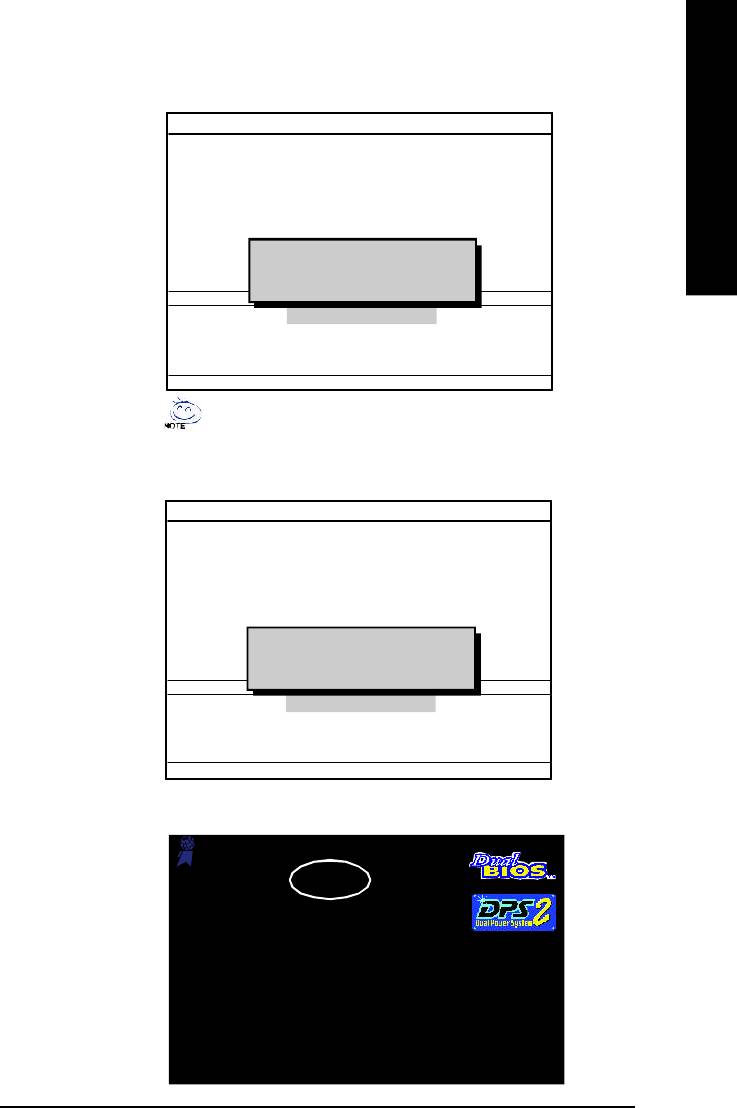
English
4. Press any keys to return to the Q-Flash menu when the BIOS updating procedure is completed.
Dual BIOS Utility
Boot Fro m.... ...... ...... ..... ...... ..... ...... ... Main Bios
Main ROM Ty p e/Siz e.... ..... .... ..... ..... ..... .SST 49LF0 03A 512K
Backup ROM Ty pe /Siz e.... .... .... ..... .... ....S ST 4 9LF0 03A 512K
Wide Range Protection Disable
Boot From M ain Bios
Auto Recov e ry E n ab l e
Halt On Err or Di sa bl e
Copy Main ROM Data to Ba ckup
!! C opy BIOS completed - Pas s !!
Load Default Setti ng s
Please press any key to continue
Sav e Settings to C M OS
Q-Flash Utility
Load M ain BIOS from Floppy
Load Backup BIOS fr om F lo pp y
Save Main BIOS to Fl op py
Save Backup BIOS to Fl op py
Enter : Run hi :M ov e ESC:Reset F10:Power Off
You can repeat Step 1 to 4 to flash the backup BIOS, too.
5. Press Esc and then Y button to exit the Q-Flash utility. The computer will restart automatically after
you exit Q-Flash.
Dual BIOS Utility
Boot Fro m.... ...... ...... ..... ...... ..... ...... ... Main Bios
Main ROM Ty p e/Siz e.... ..... .... ..... ..... ..... .SST 49LF0 03A 512K
Backup ROM Ty pe /Siz e.... .... .... ..... .... ....S ST 4 9LF0 03A 512K
Wide Range Protection Disable
Boot From M ain Bios
Auto Recov e ry Enable
Halt On Err or Di sa bl e
Copy Main ROM Data to Ba ckup
Are you sure to R ESET ?
Load Default Setti ng s
[Enter] to conti nu re or [ Esc ] to ab or t...
Sav e Settings to C M OS
Q-Flash Utility
Load M ain BIOS from Floppy
Load Backup BIOS fr om F lo pp y
Save Main BIOS to Fl op py
Save Backup BIOS to Fl op py
Enter : Run hi :M ov e ESC:Reset F10:Power Off
After system reboots, you may find the BIOS version on your boot screen becomes the one you flashed.
Aw ar d Modular BIOS v6.00PG, An Energy Star Ally
Copyright (C) 1984-2003, Award Softw ar e, Inc.
Intel i875P AGPset BIOS for 8KNXP Ultra Fba
Check System H eal th OK , VCore = 1.5250
The BIOS file becomes
Ma in P rocessor : Intel Pentium( R) 4 1. 6GH z (1 33x 1 2)
<CPUID : 0F27 Patch ID : 0027>
Fab after updating
Me mory Testin g : 13107 2K OK
Memory Frequency 266 MHz in Single Channel
Primary Ma st er : F UJ IT SU MPE31 70 AT ED- 03 -0 8
Prima ry Slav e : No ne
Secondary Master : CREATIVEDVD-RM DVD1242E BC101
Secondary Slave : None
Press DEL to enter SETUP / Dual BIOS / Q-Flash / F9 For Xpress Recovery
09/23/2003-i875P-6A79BG03C-00
- 57 -
Technical Reference
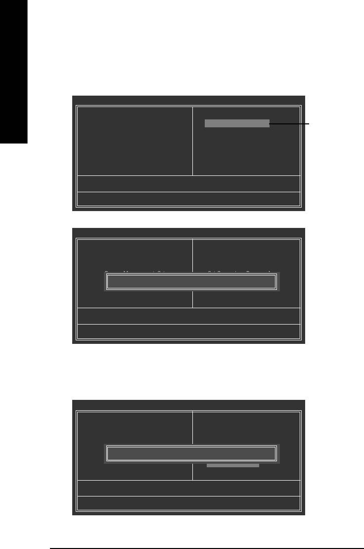
6. Press Del to enter BIOS menu after system reboots. When you are in BIOS menu, move to Load
Fail -Saf e Def au lt s item and press Enter to load BIOS Fail-Safe Defaults. Normally the system
redetects all devices after BIOS has been upgraded. Therefore, we highly recommend reloading the
BIOS defaults after BIOS has been upgraded.
English
CMOS Setup Utilit y-Copyright (C) 1984-2003 Award Soft ware
} Standard CMOS Features
Top Performance
} Advanced BIOS Features
Load Fail-Safe Default s
Press Enter on
} Integrated Peripherals
Load Optimized Defaults
your keyboard
} Power Management Setup
Set Supervisor Password
} PnP/PCI Configurations
Set User Password
} PC Health Status
Save & Exit Setup
} Frequency/Voltage Control
Exit Without Saving
ESC: Quit higf: Select Item
F8: Dual BIOS/Q-Flash F10: Save & Exit Setup
CMOS Setup Utilit y-Copyright (C) 1984-2003 Award Soft ware
} Standard CMOS Features
Top Performance
} Advanced BIOS Features
Load Fail-Safe Default s
} Integrated Peripherals
Load Optimized Defaults
} Power Management Setup
Set Supervisor Password
Press Y on your
} PnP/PCI Configurations
Load Fail-Safe Default s (Y/N)? Y
Set User Password
keyboard to
} PC Health Status
Save & Exit Setup
load defaults.
} Frequency/Voltage Control
Exit Without Saving
ESC: Quit higf: Select Item
F8: Dual BIOS/Q-Flash F10: Save & Exit Setup
7. Select Save & Exit Setup item to save the settings to CMOS and exit the BIOS menu.
System will reboot after you exit the BIOS menu. The procedure is completed.
CMOS Setup Utilit y-Copyright (C) 1984-2003 Award Soft ware
} Standard CMOS Features
Top Performance
} Advanced BIOS Features
Load Fail-Safe Default s
} Integrated Peripherals
Load Optimized Defaults
} Power Management Setup
Set Supervisor Password
Press Y on your
} PnP/PCI Configurations
Save to CMOS and EXIT (Y/N)? Y
Set User Password
keyboard to
} PC Health Status
Save & Exit Setup
} Frequency/Voltage Control
Exit Without Saving
save and exit.
ESC: Quit higf: Select Item
F8: Dual BIOS/Q-Flash F10: Save & Exit Setup
- 58 -GA-8I865P(-G) Motherboard
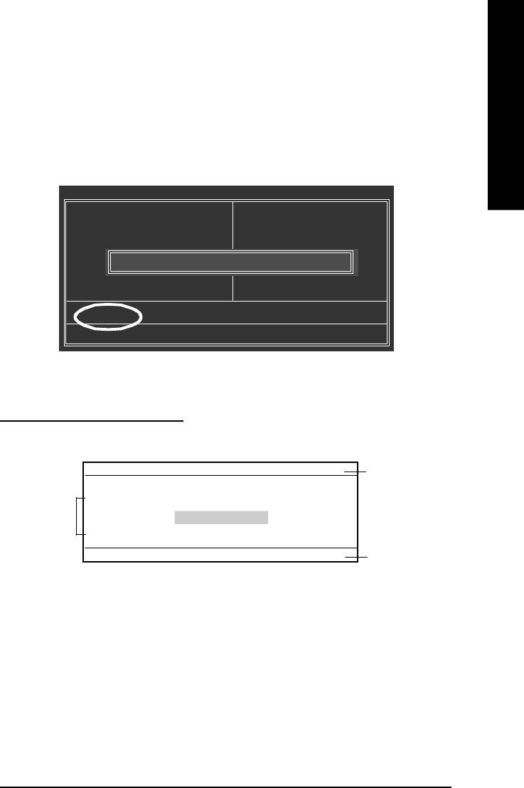
English
Part Two:
TM
Updating BIOS with Q-Flash
Utility on Single-BIOS Motherboards.
™
This part guides users of single-BIOS motherboards how to update BIOS using the Q-Flash
utility.
TM
Entering the Q-Flash
utility:
Step1: To use the Q-Flash utility, you must press Del in the boot screen to enter BIOS menu.
CMOS Setup Utilit y-Copyright (C) 1984-2003 Award Soft ware
} St andard CM OS Feat ures
Top Performance
} Advanced BIOS Features
Load Fail-Safe Default s
} Integrated Perip herals
Load Optimized Defaults
} Power Management Setup
Set Supervisor Password
Enter Q-Flash Utility (Y/N)? Y
} PnP/PCI Configurations
Set User Password
} PC Health Status
Save & Exit Setup
} Frequency/Voltage Control
Exit Without Saving
ESC: Quit higf: Select Item
F8: Q-Flash F10: Save & Exit Setup
Step 2: Press F8 button on your keyboard and then Y button to enter the Q-Flash utility.
TM
Exploring the Q-Flash
utility screen
The Q-FlashBIOS utility screen consists of the following key components.
Q-Flash Utili ty V1 .30
TM
Q-Flash
utility bar
Flash Ty p e/Size ...... ..... ...... ..... ...... .. SST 49LF0 03A 256K
Task m enu for
Keep DM I Data E n a b l e
TM
U pdate BIOS fr om F lo pp y
Q-Flash
utility
Save BIOS to Floppy
Enter : Run hi :M ov e ESC:Reset F10:Power Off
Action bar
Task menu for Q-Flash utility:
Contains the names of three tasks. Blocking a task and pressing Enter key on your keyboard to enable
execution of the task.
Action bar:
Contains the names of four actions needed to operate the Q-Flash utility. Pressing the buttons mentioned
on your keyboards to perform these actions.
- 59 -
Technical Reference
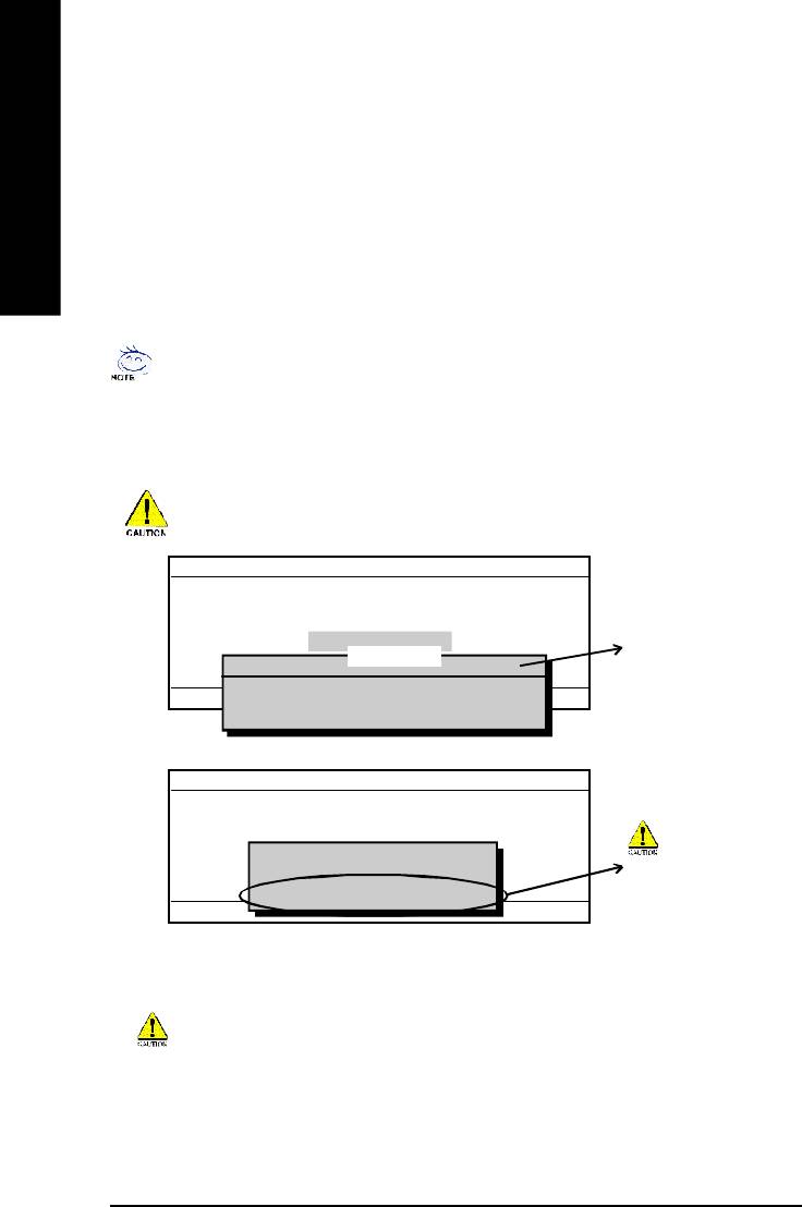
TM
Using the Q-Flash
utility:
This section tells you how to update BIOS using the Q-Flash utility. As described in the "Before you begin"
section above, you must prepare a floppy disk having the BIOS file for your motherboard and insert it to
your com puter. If you have already put the floppy disk into your system and have entered the Q-Flash
utility, please follow the steps below to flash BIOS.
English
Steps:
1. Press arrow buttons on your keyboard to m ove the light bar to "Update BIOS from Floppy" item in the
Q-Flash m enu and press Enter button.
Later, you will see a box pop up showing the BIOS files you previously downloaded to the floppy disk.
If you want to save the current BIOS for backup purpose, you can begin Step 1 with "Save BIOS
to Floppy" item.
2. Move to the BIOS file you want to flash and press Enter.
In this example, we only download one BIOS file to the floppy disk so only one BIOS file,
8GE800.F4, is listed.
Please confirm again you have the correct BIOS file for your m otherboard.
Q-Flash Utili ty V1 .30
Flash Ty p e/Size ...... ..... ...... ..... ...... .. SST 49LF0 03A 256K
Keep DM I Data E n a b l e
U pdate BIOS fr om F lo pp y
BIOS file in the floppy disk.
Save BIOS to Floppy
1 file(s) found
8GE800.F4 256K
Enter : Run hi :M ov e ESC:Reset F10:Power Off
Total size: 1.39M Fr ee siz e: 1.1 4M
F5 : Refresh DEL : Delete
Q-Flash Utili ty V1 .30
Flash Ty p e/Size ...... ..... ...... ..... ...... .. SST 49LF0 03A 256K
Keep DM I Data E n a b l e
Reading BIOS fil e from flop py . ..
U pdate BIOS fr om F lo pp y
>>>>>>>>>>>>......................
Save BIOS to Floppy
Do not trun off power or
Don't Tu rn Off Po w e r O r R ese t S y stem
reset your system at this
Enter : Run hi :M ov e ESC:Reset F10:Power Off
stage!!
After BIOS file is read, you'll see a confirmation dialog box asking you "Are you sure to update BIOS?"
Please do not take out the floppy disk when it begins flashing BIOS.
- 60 -GA-8I865P(-G) Motherboard
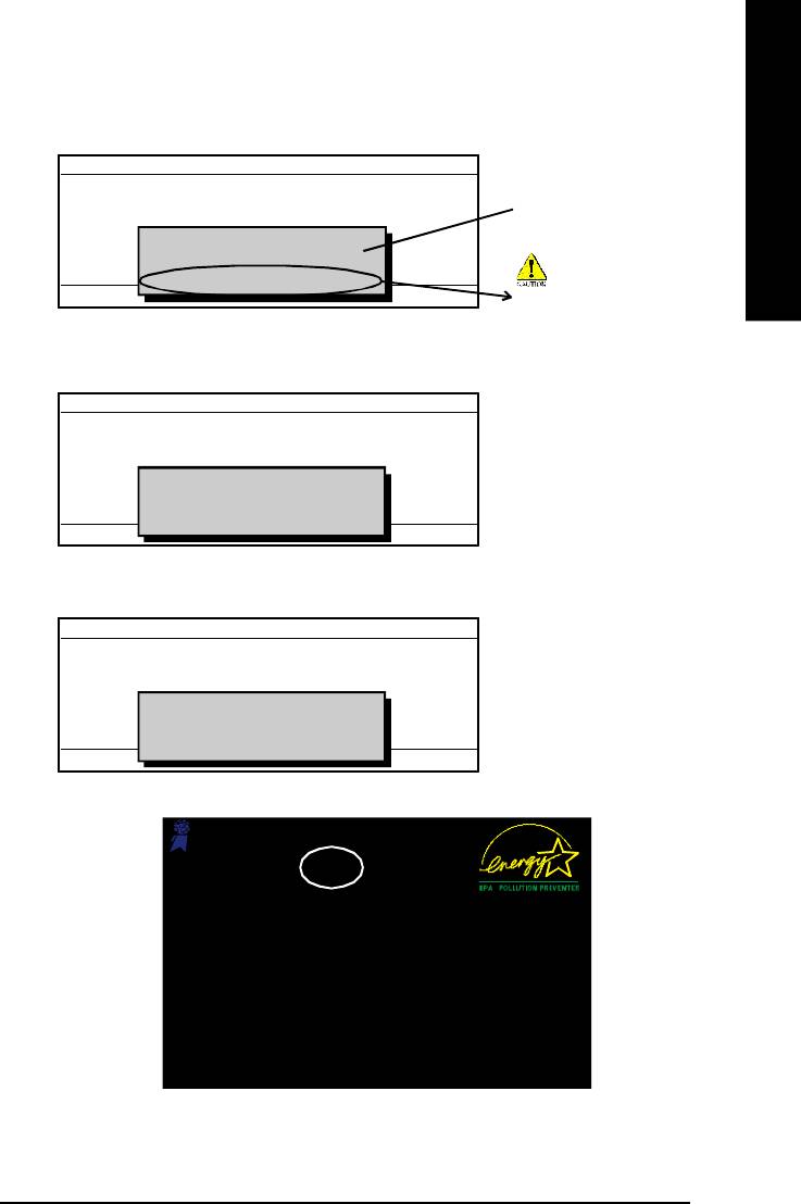
English
3. Press Y button on your keyboard after you are sure to update BIOS.
Then it will begin to update BIOS. The progress of updating BIOS will be shown at the same time.
Q-Flash Utili ty V1 .30
Flash Ty p e/Size ...... ..... ...... ..... ...... .. SST 49LF0 03A 256K
The porcess of updating
Keep DM I Data E n a b l e
U pdate BIOS fr om F lo pp y
Updating BIOS N ow...
BIOS
>>>>>>>>>>>>>>........................
Save BIOS to Floppy
Don't Tu rn Off Po w e r O r R ese t S y stem
Enter : Run hi :M ov e ESC:Reset F10:Power Off
Do not trun off power or
reset your system at this
stage!!
4. Press any keys to return to the Q-Flash menu when the BIOS updating procedure is completed.
Q-Flash Utili ty V1 .30
Flash Ty p e/Size ...... ..... ...... ..... ...... .. SST 49LF0 03A 256K
Keep DM I Data E n a b l e
U pdate BIOS fr om F lo pp y
!! C opy BIOS completed - Pas s !!
Save BIOS to Floppy
Please press any key to continue.. ... ... ..
Enter : Run hi :M ov e ESC:Reset F10:Power Off
5. Press Esc and then Y button to exit the Q-Flash utility. The computer will restart automatically after
you exit Q-Flash.
Q-Flash Utili ty V1 .30
Flash Ty p e/Size ...... ..... ...... ..... ...... .. SST 49LF0 03A 256K
Keep DM I Data E n a b l e
U pdate BIOS fr om F lo pp y
Are you sure to R ESET ?
Save BIOS to Floppy
[Enter] to conti nu re or [ Esc ] to ab or t...
Enter : Run hi :M ov e ESC:Reset F10:Power Off
After system reboots, you may find the BIOS version on your boot screen becomes the one you flashed.
Aw ar d Modular BIOS v6.00PG, An Energy Star Ally
Copyright (C) 1984-2003, Award Softw ar e, Inc.
Intel 845GE AGPSet BIOS for 8GE800 F4
The BIOS file becomes
Check System Healt h OK
Ma in P rocessor : Intel Pentium( R) 4 1 .7G Hz ( 100 x 17. 0)
Fab after updating
<CPUID : 0F0A Patch ID : 0009>
Me mory Testing : 12 288 0K OK + 8192K Shared Memo ry
Primary Ma st er : F UJ IT SU MPE31 70 AT ED- 03 -0 8
Prima ry Slav e : No ne
Secondary Master : CREATIVEDVD-RM DVD1242E BC101
Secondary Slave : None
Press DEL to enter SETUP / Q-Flash
03/18/2003-I845GE-6A69YG01C-00
6. Press Del to enter BIOS menu after system reboots and "Load BIOS Fail-Safe Defaults". See how
to Load BIOS Fail-Safe Defaults, please kindly refer to Step 6 to 7 in Part One.
Congratulation!! You have updated BIOS successfully!!
- 61 -
Technical Reference
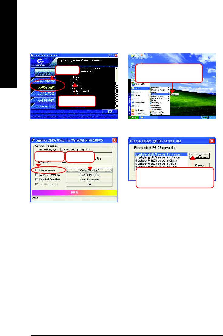
Method 2: @ BIOS Utility
TM
If you don't have DOS boot disk, we recommend that you used Gigabyte @BIOS
program to
flash BIOS.
English
Press here.
2.Click"Start"-"Programs"-
"GIGABYTE"-"@BIOS"
1.Click "@BIOS"
(2)
(1)
3.Click "P".
4.Click here.
5. Please select @BIOS sever site,
then Click "OK".
(3)
(4)
Methods and steps:
I. Update BIOS through Internet
a. Click "Internet Update" icon
b. Click "Update New BIOS" icon
TM
c. Select @BIOS
sever
d. Select the exact model name on your motherboard
e. System will automatically download and update the BIOS.
- 62 -GA-8I865P(-G) Motherboard

English
II. Update BIOS NOT through Internet:
a. Do not click "Internet Update" icon
b. Click "Update New BIOS"
c. Please select "All Files" in dialog box while opening the old file.
d. Please search for BIOS unzip file, downloading from internet or any other methods (such as:
8I865P-G.F1).
e. Complete update process following the instruction.
III. Save BIOS
In the very beginning, there is "Save Current BIOS" icon shown in dialog box. It means to save the
current BIOS version.
IV. Check out supported motherboard and Flash ROM:
In the very beginning, there is "About this program" icon shown in dialog box. It can help you check
out which kind of motherboard and which brand of Flash ROM are supported.
Note:
a. In method I, if it shows two or more motherboard's model names to be selected, please make
sure your motherboard's model name again. Selecting wrong model name will cause the
system unbooted.
b. In method II, be sure that motherboard's model name in BIOS unzip file are the same as your
motherboard's. Otherwise, your system won't boot.
TM
c. In method I, if the BIOS file you need cannot be found in @BIOS
server, please go onto
Gigabyte's web site for downloading and updating it according to method II.
d. Please note that any interruption during updating will cause system unbooted
- 63 -
Technical Reference

2- / 4- / 6- / 8- Channel Audio
Function Introduction
English
The installation of windows 98SE/2K/ME/XP is very simple. Please follow next step to install the
function!
Stereo Speakers Connection and Settings:
We recommend that you use the speaker with amplifier to acqiire the best sound effect if the stereo output
is applied.
STEP 1:
Connect the stereo speakers or earphone to "Line
Out".
Line Out
STEP 2 :
Following installation of the audio driver, you find a
icon a Sound Effect icon on the lower right hand
taskbar. Click the icon to select the function.
STEP 3:
Click "Speaker Configuration" then click on the left
selection bar and select "2CH Speaker" to com-
plete 2 channel audio configuration.
- 64 -GA-8I865P(-G) Motherboard
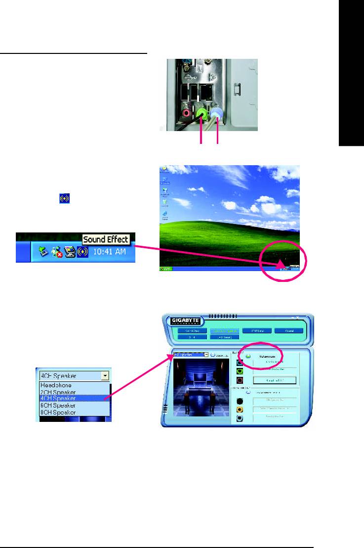
English
4 Channel Analog Audio Output Mode
STEP 1 :
Connect the front channels to "Line Out",
the rear channels to "Line In".
Line Out Line In
STEP 2 :
Following installation of the audio driver, you find a
icon a Sound Effect icon on the lower right hand
taskbar. Click the icon to select the function.
STEP 3 :
Click "Speaker Configuration" and select the "UAJ
Function". Then click on the left selection bar and
select "4CH Speaker" to complete 4 channel audio
configuration.
- 65 -
Technical Reference
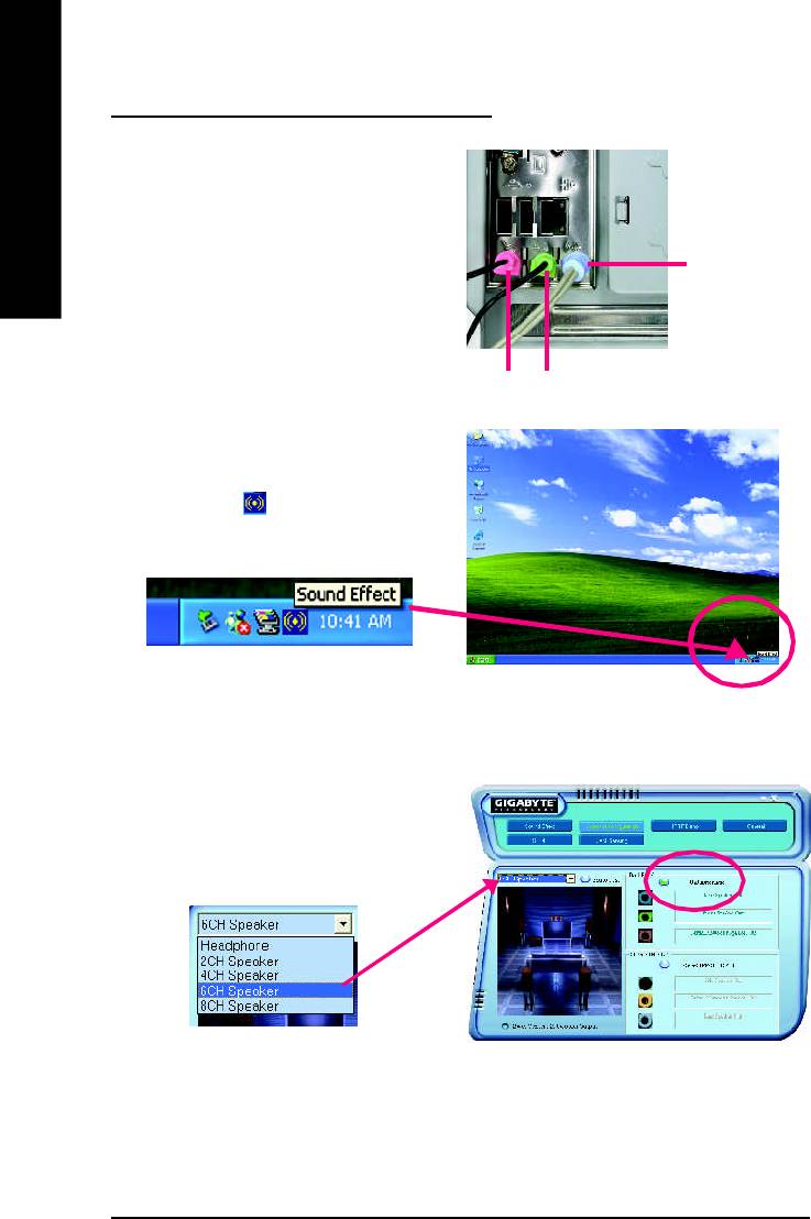
Basic 6 Channel Analog Audio Output Mode
Use the back audio panel to connect the audio out-
put without any additional module.
English
STEP 1 :
Connect the front channels to "Line Out", the rear
Line In
channels to "Line In", and the Center/Subwoofer
channels to "MIC In".
M IC In
Line Out
STEP 2 :
Following installation of the audio driver, you find a
icon a Sound Effect icon on the lower right hand
taskbar. Click the icon to select the function.
STEP 3 :
Click "Speaker Configuration" and select the "UAJ
Function". Then click on the left selection bar and
select "6CH Speaker" to complete 6 channel audio
configuration.
- 66 -GA-8I865P(-G) Motherboard
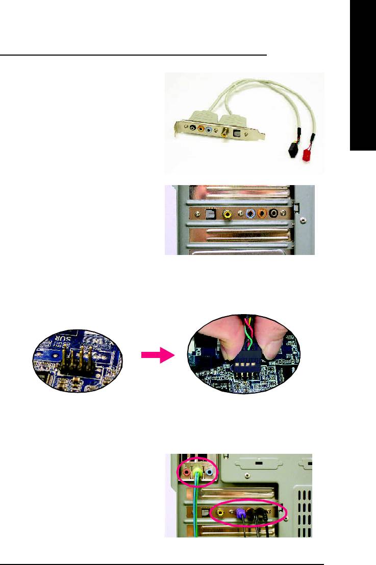
English
8 Channel Audio Setup (using Audio Combo Kit, Optional Device):
(Audio Combo Kit offers SPDIF output, an optical
and coaxial cable and a Surround-Kit. The
Surround-Kit offers R/L surround, center/subwoofer
output and rear surround)
STEP 1 :
Secure the Audio Com bo Kit at the panel on the
back of the case.
STEP 2 :
Connect the Surround-Kit to the SUR_CEN connector located on the motherboard.
STEP 3 :
Th ere are two m e thod s of 8 chan nel aud io
configuration:
M ethod 1:
Connect the front channels to the "LINE OUT"
port located on the audio panel and the rear chan-
nels to the Surround-Kit "REAR R/L" port. Con-
nect the center/subwoofer channels to the Sur-
round-Kit "SUB CENTER" and the R/L channels
to the Surround-Kit "SUR BACK" port.
- 67 -
Technical Reference
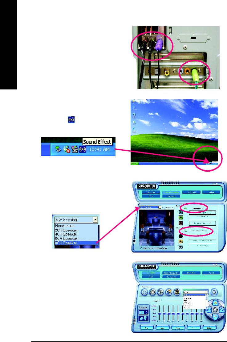
M ethod 2:
Connect the front channels to the "LINE OUT"
port located on the audio panel and the rear chan-
nels to the "LINE IN" port. Connect the center/
English
subwoofer channels to the "MIC IN" port located
on the audio panel and the R/L channels to the
Surround-Kit "SUR BACK" port. (This method
requires UAJ function)
STEP 4 :
Following installation of the audio driver, you find a
icon a Sound Effect icon on the lower right hand
taskbar. Click the icon to select the function.
STEP 5 :
Click "Speaker Configuration" and select both the
"UAJ Function" and "Only Surround-Kit". Then
click on the left selection bar and select "8CH
Speaker" to complete 8 channel audio configuration.
Sound E ffect Configu ration:
At the sound effect m enu, users can adjust
sound option settings as desired.
- 68 -GA-8I865P(-G) Motherboard
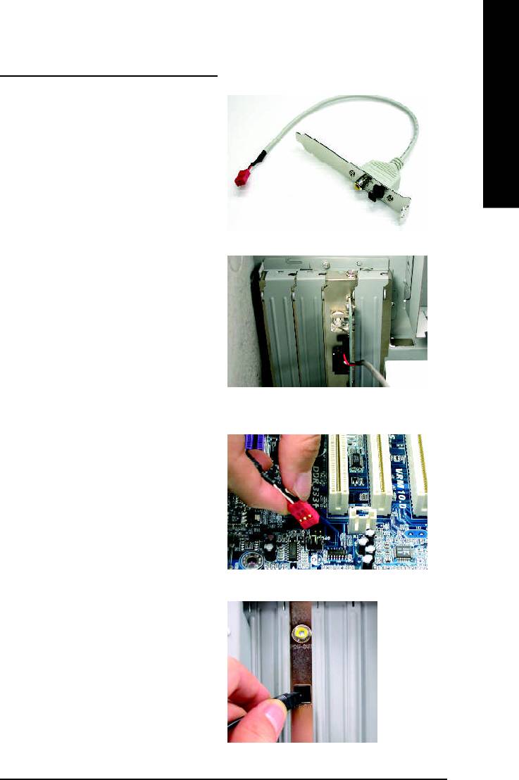
English
SPDIF Output Device (Optional Device)
A "SPDIF output" device is available on the
motherboard. Cable with rear bracket is provided
and could link to the "SPDIF output" connector (As
picture.) For the further linkage to decoder, rear
bracket provides coaxial cable and Fiber
connecting port.
1. Connect the SPDIF output device to the rear
bracket of PC, and fix it with screw.
2. Connect SPDIF device to the motherboard.
3. Connect SPDIF to the SPDIF decoder.
- 69 -
Technical Reference
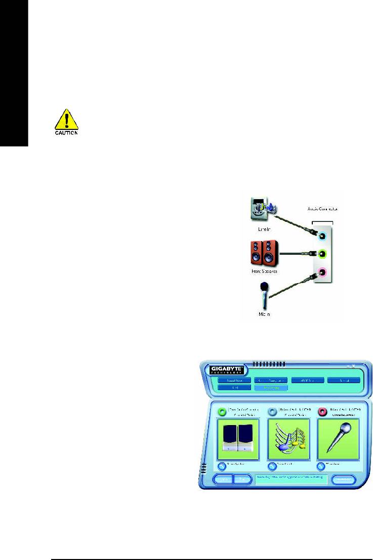
Jack-Sensing and UAJ Introduction
Jack-Sensing provides audio connectors error-detection function.
English
Install Microsoft DirectX8.1 or later version before to enable Jack-Sensing support for Windows
98/98SE/2000/ME.
Jack-Sensing includes 2 parts: AUTO and MANUAL. Following is an example for 2 channels (Windows
XP):
Introduction of audio connectors
You may connect CDROM , Walkm an or others
audio input devices to Line In jack, speakers, ear-
phone or others output devices to Line Out jack,
and microphone to MIC In jack.
Auto-detecting:
Please connect the devices to the right jacks
as above. A window will appear as right pic-
ture if you setup the devices properly.
Please note that 3D audio function will only
appear when 3D audio inputs.
- 70 -GA-8I865P(-G) Motherboard
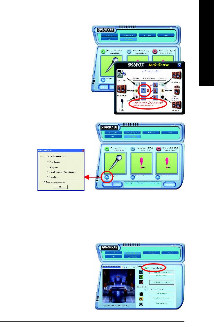
English
If you set wrong with the connectors, the warning
message will come out as right picture.
Manual setting:
If the device picture shows different from what you
set, please press "Manual Selection" to set.
UAJ Introduction
UAJ (Universal Audio Jack) has a very smart feature: It will switch signal automatically when user
plugs his audio device to the wrong jack (Line-in/ Line-out). That means users do not need to worry the
audio device should be plug in Line-in or Line-out jack, the device will work perfectly after UAJ is
activated.
Enable UAJ function:
You can click "UAJ Autom atic" button to enable
UAJ function.
- 71 -
Technical Reference

Xpress Recovery Introduction
What is Xpress Recovery ?
Xpress Recovery is a utility used to back up and restore an OS partition. If the hard drive is not
English
working properly, the user can restore the drive to its original state.
1. Supports FAT16, FAT32, and NTFS formats
2. Must be connected to the IDE1 Master
3. Allows installation of only one OS
4. Must be used with an IDE hard disk supporting HPA
5. The first partition must be set as the boot partition. When the boot partition is backed up,
please do not alter its size.
6. Xpress Recovery is recommended when using Ghost to return boot manager to NTFS
format.
How to use the Xpress Recovery
1. Boot from CD-ROM (BMP Mode)
Enter the BIOS menu, select "Advanced BIOS Feature" and set to boot from CD-ROM. Insert the
provided driver CD into your CD drive, then save and exit the BIOS menu. Once the computer has
restarted, the phrase "Boot from CD:" will appear at the bottom left-hand corner of the screen. When "Boot
from CD:" appears, press any key to enter Xpress Recovery.
Once you have completed this step, subsequent access to Xpress Recovery can also function by
pressing the F9 key during computer power on.
.
.
Verifying DMI Pool Data
Boot from CD:
Boot from CD:
Xpress Recovery V1.0 (C) Copy Right 2003. GIGABYTE Technology CO. , Ltd.
1. Execute Backup Utility
2. Execute Restore Utility
3. Remove Backup Im age
4. Set Password
5. Exit and Restart
Build 2011
- 72 -GA-8I865P(-G) Motherboard
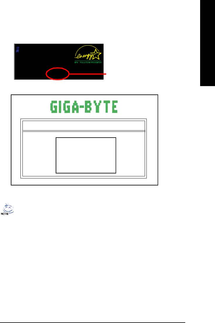
English
2. Press F9 during powering on the computer. (Text Mode)
Press F9 during powering on the computer .
Awar d Modul ar BIO S v6.00 PG, An Energy Star A l ly
Copyright (C) 1984-2002, Award Software, Inc.
Intel 865PE AGPSet BIOS for 8IPE1000MT F1
Check System Health OK
.
.
.
Press DEL to enter SETUP / Q-Flash, F9 For Xpress Recovery
F9 For Xpress Recovery
08/16/2002-I845GE-6A69YG01C-00
Xpress Recovery V1.0 (C) Copy Right 2003. GIGABYTE Technology CO. , Ltd.
1. Execute Backup Utility
2. Execute Restore Utility
3. Remove Backup Im age
4. Set Password
5. Exit and Restart
1. If you have already entered Xpress Recovery by booting from the CD-ROM, you can
enter Xpress Recovery in the future by pressing the F9 key.
2. System storage capacity as well as drive reading/writing speed will affect backup speed.
3. It is recommended that Xpress Recovery be immediately installed after OS and all
required driver and software installations are complete.
- 73 -
Technical Reference

1. Execute Backup Utility:
! Press B to Backup your System or Esc to Exit
The backup utility will automatically scan your system and back up data as a backup image in
your hard drive.
English
Not all systems support access to Xpress Recovery by pressing the F9 key during computer
power on. If this is the case, please use the boot from CD-ROM method to enter Xpress
Recovery.
2. Execute Restore Utility:
! This program will recover your system to factory default.
Press R to restore your system back to factory default or press Esc to exit
Restores backup image to original state.
3. Remove Backup Image:
! Remove backup image. Are you sure? (Y/N)
Remove the backup image.
4. Set Password:
! Please input a 4-16 character long password (a-z or 0-9) or press Esc to exit
You can set a password to enter Xpress Recovery to protect your hard disk data. Once this is done,
password input will be required to enter Xpress Recovery during the next as well as subsequent
system restarts. If you wish to remove the need for password entry, please select "Set Password"
and under "New Password/Confirm Password", make sure there is no entry and then press
"Enter" to remove password requirement.
5. Exit and Restart:
Exit and restart your computer.
- 74 -GA-8I865P(-G) Motherboard
Оглавление
- DECLARATION OF CONFORMITY
- Chapter 5 Appendix
- FAQ
- Troubleshooting
- Technical Support/RMA Sheet
- Acronyms


