Gigabyte GA-8IP900MK: инструкция
Раздел: Компьютерная техника, комплектующие, аксессуары
Тип: Материнская Плата
Инструкция к Материнской Плате Gigabyte GA-8IP900MK
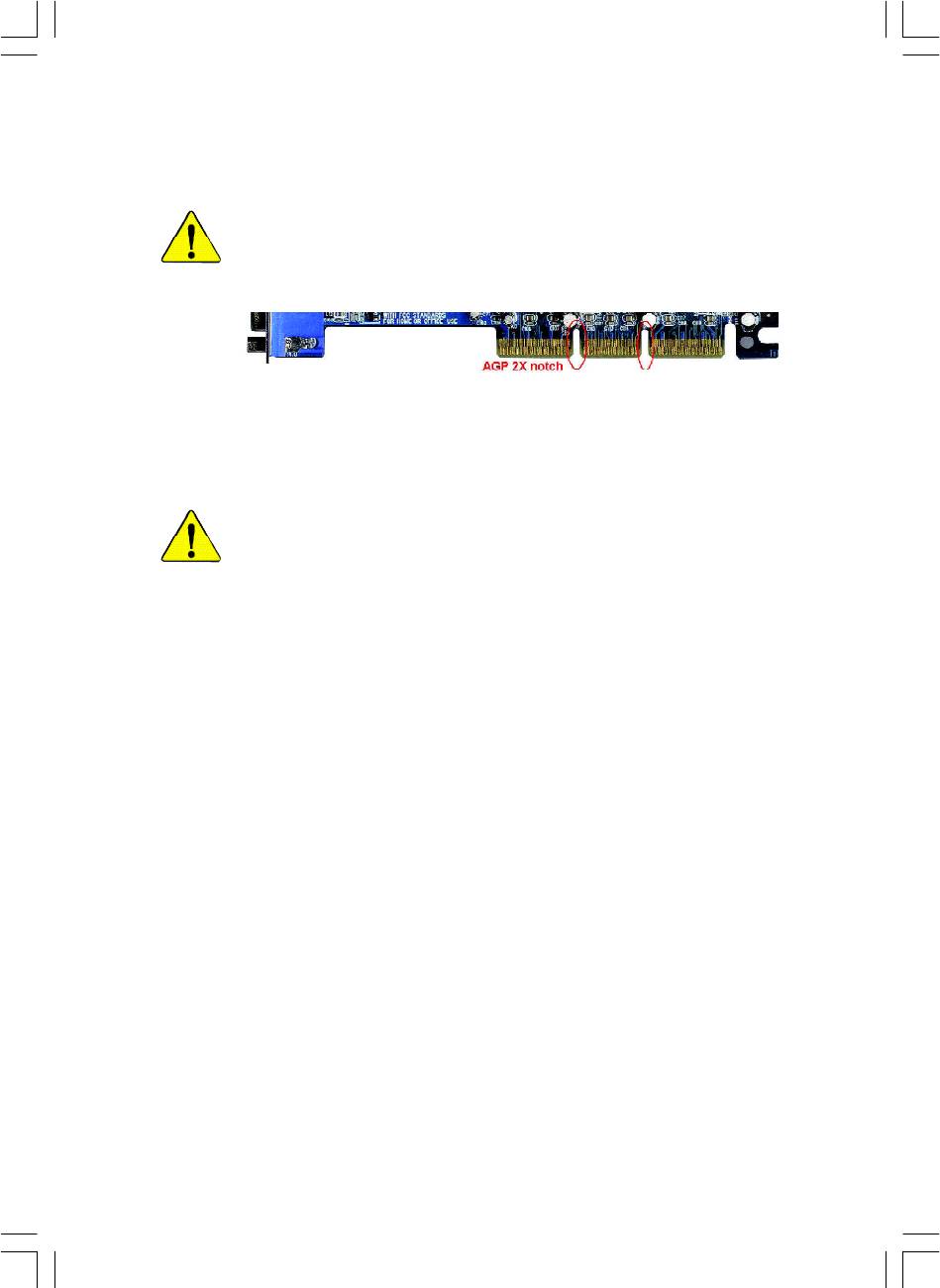
When you installing AGP card, please make sure the following notice
is fully understood and practiced. If your AGP card has "AGP 4X/8X
(1.5V) notch"(show below), please make sure your AGP card is AGP
4X/8X (1.5V).
AGP 4X/8X notch
®
Caution: AGP 2X card is not supported by Intel
845(GE/PE) / 845(E/G)
/ 850(E) / E7205 / 865(G/PE/P) / 875P. You might experience system
unable to boot up normally. Please insert an AGP 4X/8X card.
Example 1: Diamond Vipper V770 golden finger is compatible with 2X/4X
mode AGP slot. It can be switched between AGP 2X(3.3V) or 4X/8X(1.5V)
mode by adjusting the jumper. The factory default for this card is 2X(3.3V).
The GA-8IP900MK (or any AGP 4X/8X only) motherboards might not
function properly, if you install this card without switching the jumper to 4X/8X
(1.5) mode in it.
Example 2: Some ATi Rage 128 Pro graphics cards made by "Power Color",
the graphics card manufacturer & some SiS 305 cards, their golden finger is
compatible with 2X(3.3V)/4X(1.5V) mode AGP slot, but they support 2X(3.3V)
only. The GA-8IP900MK (or any AGP 4X/8X only) motherboards might not
function properly, If you install this card in it.
Note : Although Gigabyte's AG32S(G) graphics card is based on ATi Rage
128 Pro chip, the design of AG32S(G) is compliance with AGP 4X(1.5V)
®
specification. Therefore, AG32S(G) will work fine with Intel
845(GE/PE) /
845(E/G) / 850(E) / E7205 / 865(G/PE/P) / 875P based motherboards.
8ip900mk_1001_f.p65 2003/4/22, 下午 03:5193
The author assumes no responsibility for any errors or
omissions that may appear in this document nor does the
author make a commitment to update the information
contained herein.
Third-party brands and names are the property of their
respective owners.
Please do not remove any labels on motherboard, this may
void the warranty of this motherboard.
Due to rapid change in technology, some of the
specifications might be out of date before publication of
this booklet.
8ip900mk_1001_f.p65 2003/4/22, 下午 03:5194

Declaration of Conformity
We, Manufacturer/Importer
(full address)
G.B.T. Technology Träding GMbH
Ausschlager Weg 41, 1F, 20537 Hamburg, Germany
declare that the product
( description of the apparatus, system, installation to which it refers)
Mother Board
GA-8IP900MK
is in conformity with
(reference to the specification under which conformity is declared)
in accordance with 89/336 EEC-EMC Directive
o EN 55011 Limits and methods of measurement
o EN 61000-3-2*
Disturbances in supply systems cause
of radio disturbance characteristics of
T EN 60555-2
by household appliances and similar
industrial,scientific and medical (ISM
electrical equipment “Harmonics”
high frequency equipment
o EN 55013
Limits and methods of measurement
o EN 61000-3-3* Disturbances in supply systems cause
of radio disturbance characteristics of
by household appliances and similar
T EN 60555-3
broadcast receivers and associated
electrical equipment “Voltage fluctuations”
equipment
o EN 55014 Limits and methods of measurement
T EN 50081-1
Generic emission standard Part 1:
of radio disturbance characteristics of
Residual commercial and light industry
household electrical appliances,
portable tools and similar electrical
T EN 50082-1
Generic immunity standard Part 1:
apparatus
Residual commercial and light industry
o EN 55015 Limits and methods of measurement
o EN 55081-2
Generic emission standard Part 2:
of radio disturbance characteristics of
Industrial environment
fluorescent lamps and luminaries
o EN 55020
Immunity from radio interference of
o EN 55082-2
Generic emission standard Part 2:
broadcast receivers and associated
Industrial environment
equipment
T EN 55022 Limits and methods of measurement
o ENV 55104
lmmunity requirements for household
of radio disturbance characteristics of
appliances tools and similar apparatus
information technology equipment
o DIN VDE 0855
Cabled distribution systems; Equipment
o EN50091-2
EMC requirements for uninterruptible
o part 10
for receiving and/or distribution from
power systems (UPS)
o part 12
sound and television signals
T CE marking
(EC conformity marking)
The manufacturer also declares the conformity of above mentioned product
with the actual required safety standards in accordance with LVD 73/23 EEC
o EN 60065
Safety requirements for mains operated
o EN 60950
Safety for information technology equipment
electronic and related apparatus for
including electrical bussiness equipment
household and similar general use
o EN 60335
Safety of household and similar
o EN 50091-1
General and Safety requirements for
electrical appliances
uninterruptible power systems (UPS)
Manufacturer/Importer
Signature:
Timmy Huang
Date : April 8, 2003
Name:
(Stamp)
Timmy Huang
8ip900mk_1001_f.p65 2003/4/22, 下午 03:5295

DECLARATION OF CONFORMITY
Per FCC Part 2 Section 2.1077(a)
Responsible Party Name:
G.B.T. INC. (U.S.A.)
Address:
17358 Railroad Street
City of Industry, CA 91748
Phone/Fax No:
(818) 854-9338/ (818) 854-9339
hereby declares that the product
Product Name: Motherboard
Model Number: GA-8IP900MK
Conforms to the following specifications:
FCC Part 15, Subpart B, Section 15.107(a) and Section 15.109(a),
Class B Digital Device
Supplementary Information:
This device complies with part 15 of the FCC Rules. Operation is
subject to the following two conditions: (1) This device may not
cause harmful and (2) this device must accept any inference received,
including that may cause undesired operation.
Representative Person’s Name:
ERIC LU
Signature:
Eric Lu
Date:
April 8, 2003
8ip900mk_1001_f.p65 2003/4/22, 下午 03:5296

GA-8IP900MK
P4 Titan Series Motherboard
USER'S MANUAL
®
Pentium
4 Processor Motherboard
Rev. 1001
12ME-8IP900MK-1001

Table of Content
English
Item Checklist ..................................................................................4
Chapter 1 Introduction ......................................................................5
Features Summary................................................................................................ 5
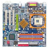
GA-8IP900MK Motherboard Layout ................................................................... 7
Block Diagram ....................................................................................................... 8
Chapter 2 Hardware Installation Process ......................................... 11
Step 1: Install the Central Processing Unit (CPU) ......................................... 12
Step 1-1: CPU Installation ............................................................................ 12
Step 1-2: CPU Cooling Fan Installation .......................................................... 13
Step 2: Install Memory Modules ....................................................................... 14
Step 3: Install expansion cards ......................................................................... 16
Step 4: Connect ribbon cables, cabinet wires and power supply ..............17
Step 4-1: I/O Back Panel Introduction ............................................................ 17
Step 4-2: Connectors Introduction ................................................................. 19
Chapter 3 BIOS Setup .................................................................... 33
The Main Menu (For example: BIOS Ver. : F2 ) ............................................ 34
Standard CMOS Features ................................................................................. 36
Advanced BIOS Features................................................................................... 39
Integrated Peripherals ....................................................................................... 41
Power Management Setup ................................................................................ 46
PnP/PCI Configurations ...................................................................................... 49
PC Health Status .................................................................................................. 50
Frequency/Voltage Control ................................................................................ 52
Load Fail-Safe Defaults ...................................................................................... 54
- 2 -GA-8IP900MK Motherboard

English
Load Optimized Defaults .................................................................................... 55
Set Supervisor/User Password .......................................................................... 56
Save & Exit Setup ................................................................................................. 57
Exit Without Saving ............................................................................................. 58
Chapter 4 Technical Reference ....................................................... 61
@BIOS™ Introduction ........................................................................................ 61
EasyTune™ 4 Introduction ................................................................................ 62
Flash BIOS Method Introduction ...................................................................... 63
Method 1 : Q-Flash .................................................................................... 63
Method 2 : @BIOS Utility ............................................................................ 65
2- / 4- / 6-Channel Audio Function Introuction ............................................... 67
Jack-Sensing Introuction ................................................................................... 73
Chapter 5 Appendix ....................................................................... 77
- 3 -
Table of Content
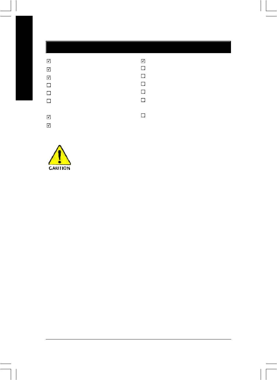
Item Checklist
The GA-8IP900MK motherboard
Serial ATA cable x 2
CD for motherboard driver & utility
2 Port USB Cable x 1
English
GA-8IP900MK user's manual
4 Port USB Cable x 1
Quick PC Installation Guide
SPDIF Kit x 1 (SPDIF Out Kit)
SATA RAID Manual
IEEE 1394 Cable x1
GC-SATA Card (optional)
Audio Combo Kit x 1
(Manual; SATA ca ble x 1; Power cable x 1)
(SURROUND-Kit + SPDIF Out Kit)
I/O Shield
Motherboard Settings Label
IDE cable x 1 / Floppy cable x 1
Computer motherboards and expansion cards contain very delicate Integrated Circuit
(IC) chips. To protect them against damage from static electricity, you should follow
some precautions whenever you work on your computer.
1. Unplug your computer when working on the inside.
2. Use a grounded wrist strap before handling computer components. If you do not have one, touch
both of your hands to a safely grounded object or to a metal object, such as the power supply
case.
3. Hold components by the edges and try not touch the IC chips, leads or connectors, or other
components.
4. Place components on a grounded antistatic pad or on the bag that came with the components
whenever the components are separated from the system.
5. Ensure that the ATX power supply is switched off before you plug in or remove the ATX power
connector on the motherboard.
Installing the motherboard to the chassis...
If the motherboard has mounting holes, but they don't line up with the holes on the base and there are
no slots to attach the spacers, do not become alarmed you can still attach the spacers to the mounting
holes. Just cut the bottom portion of the spacers (the spacer may be a little hard to cut off, so be careful of
your hands). In this way y ou can still attach the motherboard to the base without worrying about short
circuits. Sometimes you may need to use the plastic springs to isolate the screw from the motherboard
PCB surface, because the circuit wire may be near by the hole. Be careful, don't let the screw contact
any printed circuit write or parts on the PCB that are near the fixing hole, otherwise it may damage the
board or cause board malfunctioning.
- 4 -GA-8IP900MK Motherboard

English
Chapter 1 Introduction
Features Summary
Form Factor — 24.4cm x 24.4cm Micro ATX size form factor, 4 layers PCB
®
®
CPU — Socket 478 for Intel
Micro FC-PGA2 Pentium
4 processor
®
®
— Support Intel
Pentium
4 (Northwood, Prescott) processor
®
®
— Support Intel
Pentium
4 Processor with HT Technology *
®
®
— Intel
Pentium
4 533/400MHz FSB
— 2nd cache depends on CPU
®
Chipset — Intel
Chipset 865P HOST/AGP/Controller
®
— Intel
ICH5 I/O C ontroller Hub
Memory — 4 184-pin DDR DIMM sockets
— Supports Dual C hannel DDR333/DDR266 DIMM
— Supports 128MB/256MB/512MB/1GB unbuffered DRAM
— Supports up to 4GB DRAM (Max)
— Supports only DDR DIMM
I/O Control — ITE8712F
Slots — 3 PCI slot supports 33MHz & PCI 2.3 compliant
On-Board IDE — 2 IDE controllers provides IDE HDD/CD-ROM (IDE1, IDE2) with
PIO, Bus Master (U ltra DMA33/ATA66/ATA100) operation modes
— Can connect up to 4 IDE devices
Serial ATA — 2 Serial ATA connectors in 150 MB/s operation mode
— Controlled by ICH5
On-Board Peripherals — 1 Floppy port supports 2 FDD with 360K, 720K,1.2M, 1.44M
and 2.88M bytes
— 1 Parallel port supports Normal/EPP/EC P mode
— 2 Serial ports (COMA & COMB)
— 8 USB 2.0/1.1 ports (4 x Rear, 4 x Front by cable)
— 1 IrDA connector for IR/CIR
— 1 Front Audio connector
Hardware Monitor — CPU/Sy stem fan revolution detect
— CPU temperature detect
— CPU warning temperature
— System voltage detect
— CPU/System fan fail warning
®
On-Board LAN — Builit in Intel
82562 Chipset
Data transfer rate 10/100 supported
— 1 RJ45 port
to be continued......
- 5 -
Introduction

On-Board Sound — Realtek ALC655 codec
— Supports Jack Sensing function
— Line Out / 2 front speaker
— Line In / 2 rear speaker (by s/w sw itch)
English
— Mic In / center & subwoofer (by s/w switch)
— CD In / AUX In / Game port
PS/2 Connector — PS/2 Keyboard interface and PS/2 Mouse interace
BIOS — Licensed Phoenix BIOS, 2M bit FWH
Additional Features — PS/2 Keyboard pow er on by password
— PS/2 Mouse pow er on
— STR (Suspend-To-RAM)
— AC Recovery
— Poly fuse for key board over-current protection
— USB KB/Mouse w ake up from S3
— Supports @BIOS
— Supports EasyTune 4
— Supports clear password function
"*" HT functionality requirement content :
Enabling the functionality of Hy per-Threading Technology for your computer system requires all
of the following platform components:
®
- CPU: An Intel
Pentium 4 Processor with HT Technology
®
- Chipset: An Intel
Chipset that supports HT Technology
- BIOS: A BIOS that supports HT Technology and has it enabled
- OS: An operation system that has optimizations for HT Technology
Please set the CPU host frequency in accordance w ith your processor's specifications.
We don't recommend you to set the sy stem bus frequency over the CPU's specification because
these specific bus frequencies are not the standard specifications for CPU, chipset and most of the
peripherals. Whether your system can run under these specific bus frequencies properly w ill
depend on your hardw are configurations, including CPU, Chipsets, SDRAM, Cards… etc.
- 6 -GA-8IP900MK Motherboard
English
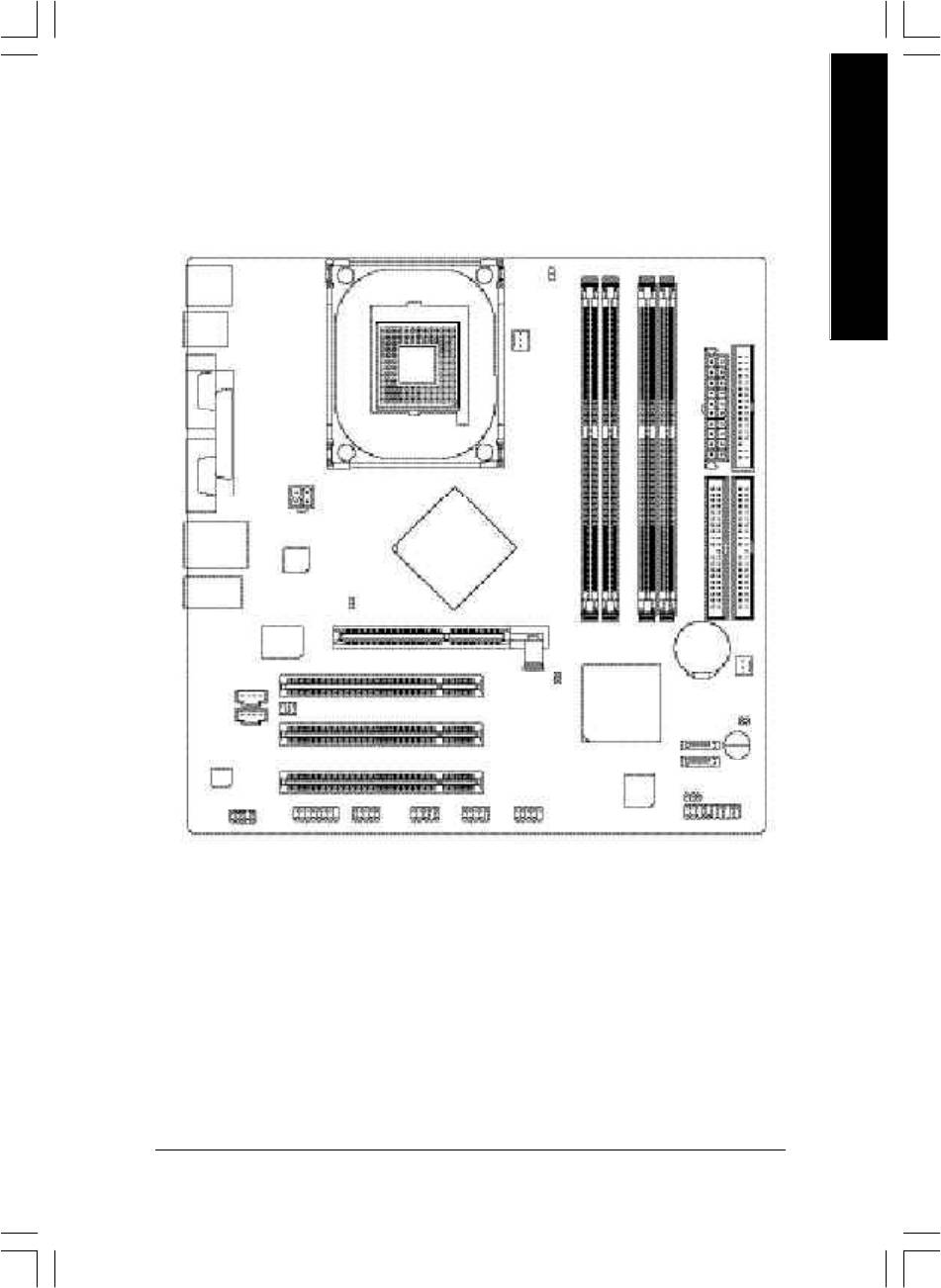
GA-8IP900MK Motherboard Layout
KB_MS
DIMM_LED
R_USB
ATX
FDD
CPU_FAN
COMA
SOCKET 478
LPT
ATX_12V
COMB
USB
LAN
Intel
Intel 865P
82562EZ
GA-8IP900MK
AUDIO1
2X_DET
IDE2
ITE
IDE1
8712F
DDR1
DDR2
DDR3
DDR4
BAT
AGP
PCI1
CLR_PWD
SYS _FAN
CD_IN
Intel ICH5
AUX_IN
SUR_CEN
PCI2
CI
SATA1
CODEC
PCI3
Buzzer
SATA0
BIOS
F_AUDIO
GAME INFO_LINK
IR_CIR
F_USB1
F_USB2
PWR_LED
F_PANEL
- 7 -
Introduction
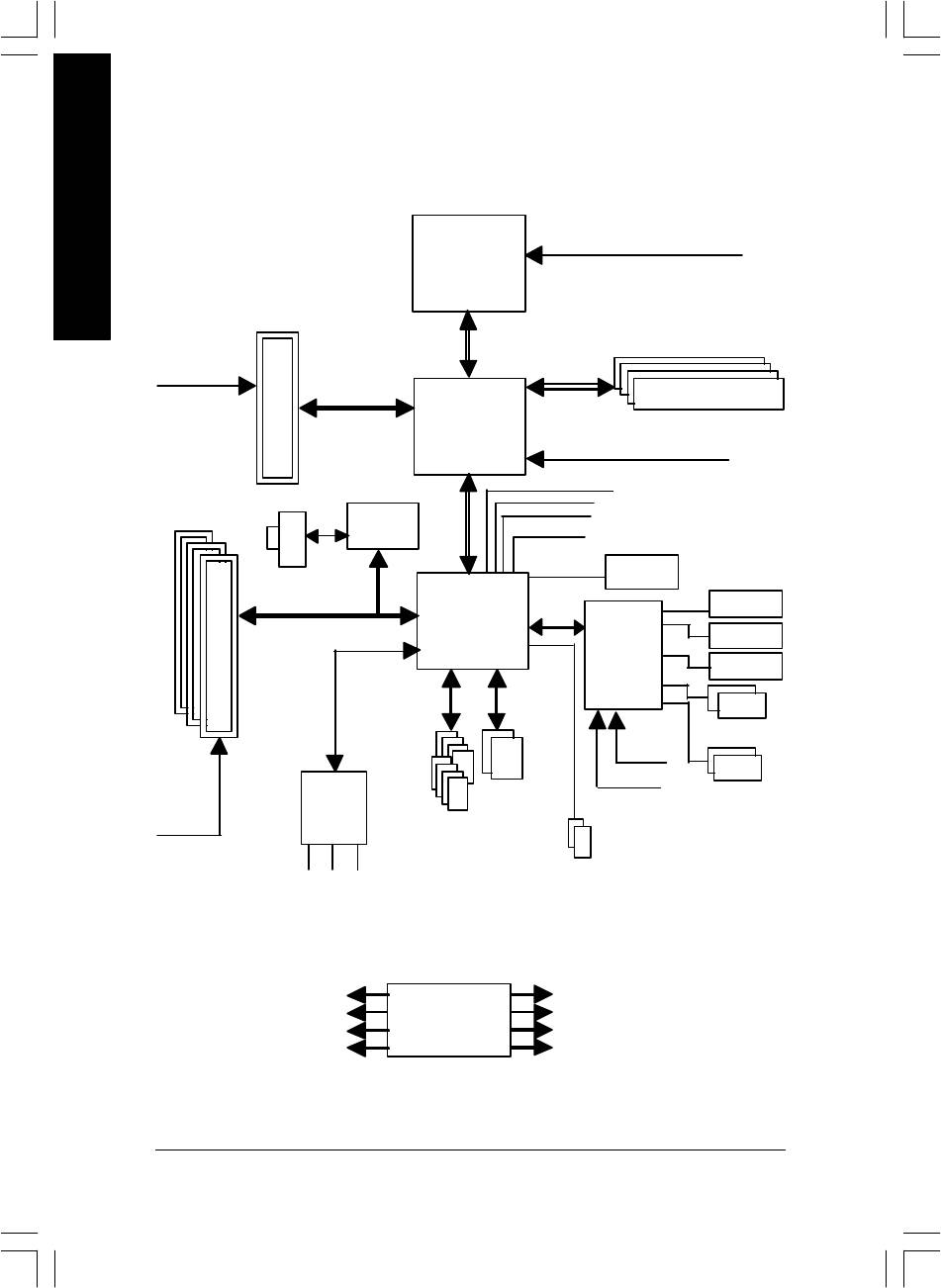
Block Diagram
English
Pentium 4
CPUCLK+/- (100/133 MHz)
Socket 478
CPU
AGP 4X/8X
System Bus
266/333MHz
AGPCLK
533/400MHz
(66MHz)
DDR RAM
Intel 865P
MCHCLK (100/133 MHz)
66 MHz
33 MHz
3 PCI
Intel
14.318 MHz
48 MHz
82562EZ
RJ45
BIOS
Intel
LPC BUS
Game Port
ICH5
Floppy
IT8712F
LPT Port
AC97 Link
PS/2 KB/Mouse
24 MHz
33 MHz
AC97
ATA33/66/100
2 COM Ports
CODEC
IDE Channels
8 USB
Ports
2 Serial ATA
PCICLK
(33MHz)
MIC
LINE-IN
LINE-OUT
PCICLK (33MHz)
CPUCLK+/- (100/133MHz)
USBCLK (48MHz)
AGPCLK (66MHz)
CLK GEN
14.318 MHz
MCHCLK (100/133MHz)
33 MHz
ICH3V66 (66MHz)
- 8 -GA-8IP900MK Motherboard

English
- 9 -
Introduction

English
- 10 -GA-8IP900MK Motherboard
English
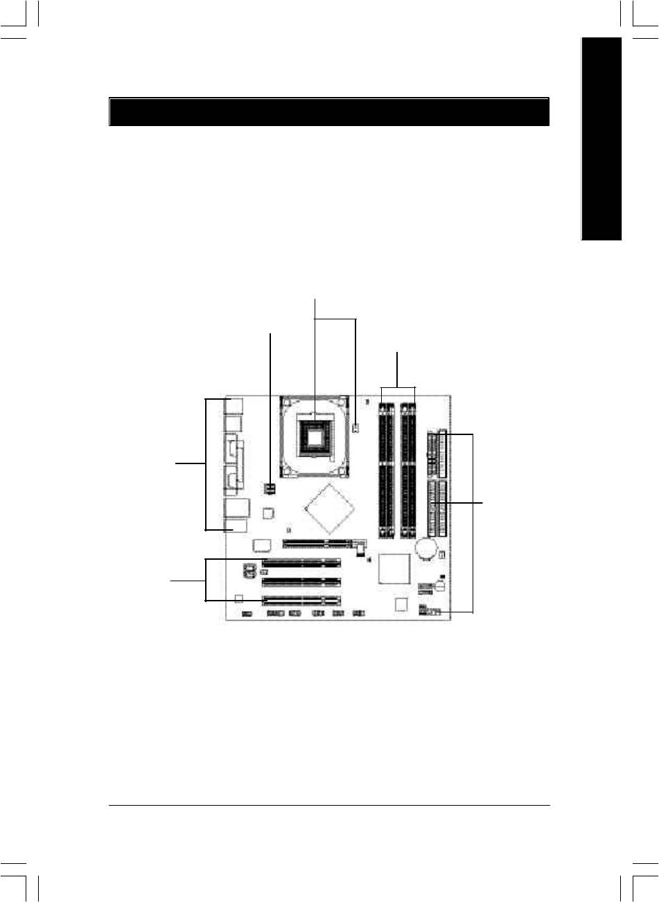
Chapter 2 Hardware Installation Process
To set up your computer, you must complete the following steps:
Step 1- Install the Central Processing Unit (CPU)
Step 2- Install memory modules
Step 3- Install expansion cards
Step 4- Connect ribbon cables, cabinet wires, and power supply
Step 1
Step 4
Step 2
Step 4
Step 4
Step 3
Congratulations! You have accomplished the hardware installation!
Turn on the power supply or connect the power cable to the power outlet. Continue with the
BIOS/software installation.
- 11 - Hardware Installation Process
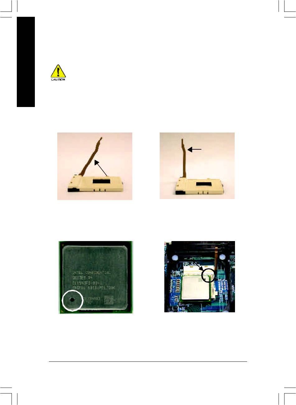
Step 1: Install the Central Processing Unit (CPU)
Before installing the processor, adhere to the following warning:
English
1. Please make sure the CPU type is supported by the motherboard.
2. If you do not match the CPU socket Pin 1 and CPU cut edge well, it will
cause improper installation. Please change the insert orientation.
Step 1-1: CPU Installation
Socket
Angling the
Actuation
0
rod to 65
Lever
1. Angling the rod to 65-degree maybe
2. Pull the rod to the 90-degree directly.
feel a kind of tight , and then continue
pull the rod to 90-degree when a noise
"cough" made.
Pin1 indicator
Pin1 indicator
3. CPU Top View
4. Locate Pin 1 in the socket and
look for a (golden) cut edge on the
CPU upper corner. Then insert
the CPU into the socket.
- 12 -GA-8IP900MK Motherboard
English
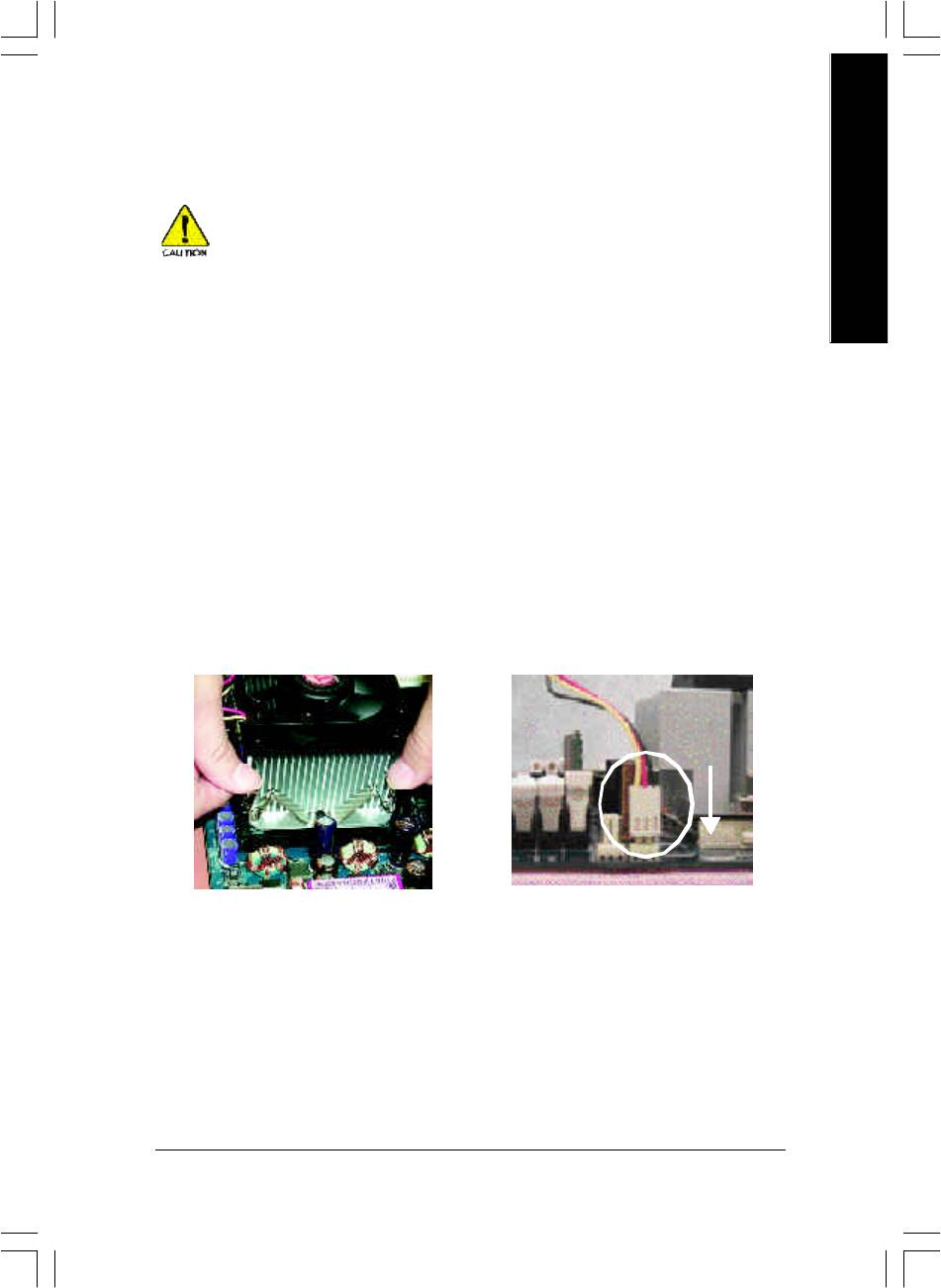
Step 1-2: CPU Cooling Fan Installation
Before installing the CPU cooling fan, adhere to the following warning:
1. Please use Intel approved cooling fan.
2. We recommend you to apply the thermal tape to provide better heat
conduction between your CPU and cooling fan.
(The CPU cooling fan might stick to the CPU due to the hardening of
the thermal paste. During this condition if you try to remove the cool-
ing fan, you might pull the processor out of the CPU socket alone with
the cooling fan, and might damage the processor. To avoid this from
happening, we suggest you to either use thermal tape instead of
thermal paste, or remove the cooling fan with extreme caution.)
3. Make sure the CPU fan power cable is plugged in to the CPU fan
connector, this completes the installation.
Please refer to CPU cooling fan user's manual for more detail
installation procedure.
1. Fasten the cooling fan supporting-
2. Make sure the CPU fan is plugged
base onto the CPU socket on the
to the CPU fan connector, than
motherboard.
install complete.
- 13 - Hardware Installation Process
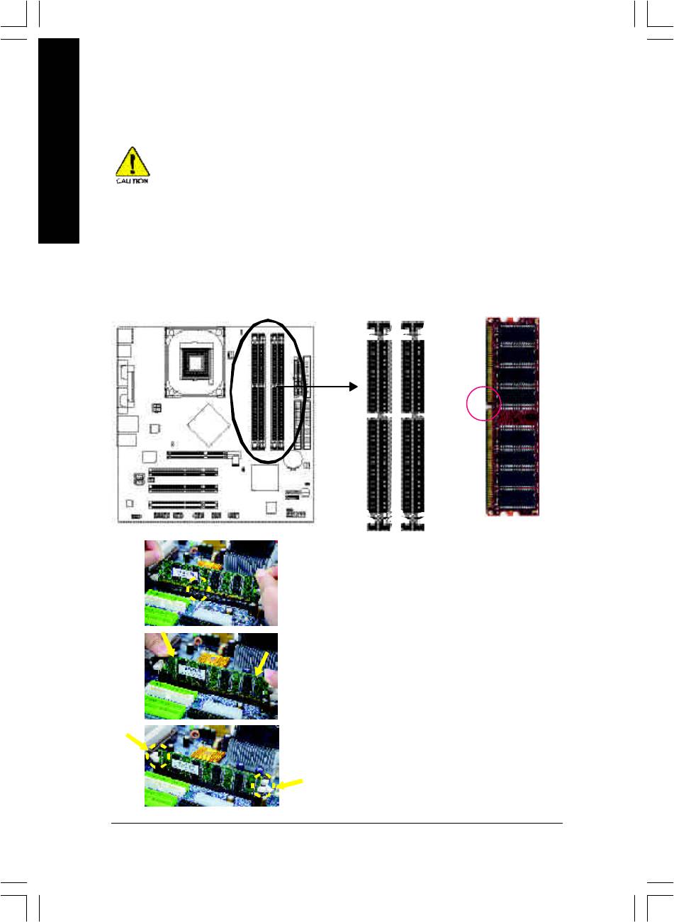
Step 2: Install Memory Modules
Before installing the memory modules, adhere to the following warning:
1. When DIMM LED is ON, do not install / remove DIMM from socket.
English
2. Please note that the DIMM module can only fit in one direction due to
the one notch. Wrong orientation will cause improper installation.
Please change the insert orientation.
The motherboard has 4 dual inline memory module (DIMM) sockets. The BIOS will automatically
detects memory type and size. To install the memory module, just push it vertically into the DIMM
socket. The DIMM module can only fit in one direction due to the notch. Memory size can vary
between sockets.
Notch
DDR
1. The DIMM s ocket has a notch, so the DIMM memory
module can only fit in one direction.
2. Insert the DIMM memory module vertically into the DIMM
socket. Then push it down.
3. Close the plas tic clip at both edges of the DIMM sockets
to lock the DIMM module.
Reverse the installation steps w hen you wish to remove
the DIMM mod ule.
- 14 -GA-8IP900MK Motherboard

English
DDR Introduction
Established on the existing SDRAM industry infrastructure, DDR (Double Data R ate) memory is a
high perfor mance and cost-effective solution that allows easy adoption for memory v endors, OEMs
and sy stem integrators.
DDR memory is a sensible ev olutionary solution for the PC industry that builds on the existing
SDRAM infrastruc ture, yet makes awesome advances in solving the system performance bottleneck
by doubling the memory bandwidth. DDR SDRAM will offer a superior solution and migration path from
existing SDRAM designs due to its avail ability, pricing and overall market support. PC2100 DDR
memory (DDR266) doubles the data rate through readi ng and writing at both the rising and falling edge
of the cl ock, achieving data bandwidth 2X greater than PC133 w hen running with the same DRAM
clock frequency . With peak bandwidth of 2.664 GB per second, DDR memory enables system OEMs
to build high performance and low latency DRAM subsystems that are suitable for servers, workstations,
high-end PC's and value desktop SMA systems.
Dual Channel DDR:
GA-8IP900MK supports Dual Channel Technology.
When Dual Channel Technology is activated, the bandwidth of memory bus will be double the original
one,w ith the fastest speed at 5.3GB/s DDR333.
GA-8IP900MK includes four DIMM slots, and each Channel has 2 DIMMs as following:
Channel A : DIMM 1, 2
Channel B : DIMM 3, 4
Below are the explanations:
If you want to operate the Dual Channel Technology, please note the following ex planations
due to the limitation o f Intel chipset specifications.
1. Only one DDR memory module is installed: The Dual Channel Technology can't
operate when only one DDR memory module is installed. Additionally, you can boot the
system only when the memory module is inserted into Channel A. On the other hand,
the memory module must be inserted into DIMM1 or DIMM3 sockets.
2. Two DDR memory modules are installed (the same memory size and type): The Dual
Channel Technology will operate when two memory modules are inserted indiv idually
into Channel A and B. If y ou install two memory modules in the same channel, the Dual
Channel Technology will not operate. Additionally, y ou can boot the system only when
one of the memory modules is inserted into Channel A. On the other hand, the memory
module must b e inserted into DIMM1 or DIMM3 sockets.
3. Three DDR memory modules are installed: Please note that the Dual Channel Technol-
ogy will "not" operate when three DDR memory modules are installed. If you install
three memory modules, the system will only detect those memory modules inserted in
Channel A, and those in Channel B will not be detected!
- 15 - Hardware Installation Process
4. Four DDR memory modules are installed: If you install four memory modules at the same time, the
Dual Channel Technology will operate only when those modules have the same memory size and
type.
The following tables include all memory-installed combination types:
English
(Please note that those types not in the tables will not boot up.)
l Figure 1: Dual Channel Technology (DS: Double Side, SS: Single Side)
DIMM 1 DIMM 2 DIMM 3 DIMM 4
2 memory modules
DS/SS X DS/SS X
X DS/SS X DS/SS
4 memory modules
DS/SS DS/SS DS/SS DS/SS
l Figure 2: Don't operate Dual Channel Technology (DS: Double Side, SS: Single Side)
DIMM 1 DIMM 2 DIMM 3 DIMM 4
1 memory mo dule
DS/SS X X X
X X DS/SS X
2 memory mod ules
DS/SS DS/SS X X
Step 3: Install expansion cards
1. Read the related expansion card's instruction document before install the expansion card into the
computer.
2. Remove your computer's chassis cover, screws and slot bracket from the computer.
3. Press the expansion card firmly into expansion slot in motherboard.
4. Be sure the metal contacts on the card are indeed seated in the slot.
5. Replace the screw to secure the slot bracket of the expansion card.
6. Replace your computer's chassis cover.
7. Power on the computer, if necessary, setup BIOS utility of expansion card from BIOS.
8. Install related driver from the operating system.
Please carefully pull out the small white-drawable
bar at the end of the AGP slot w hen yo u try to
instal l/ Uninstall the AGP card. Please align the
AGP card to the onboard AGP slot and press firmly
down on the slot .Make s ure your AGP card is
AGP Card
locked by the small white- drawable bar.
When an AGP 2X (3.3V) card is installed the 2X_DET w ill light up, indicating a non-supported
graphics card is inserted. Informing users that sy stem might not boot up normally due to
AGP 2X (3.3V) is not supported by the chipset.
- 16 -GA-8IP900MK Motherboard
English
Step 4: Connect ribbon cables, cabinet wires and
power supply
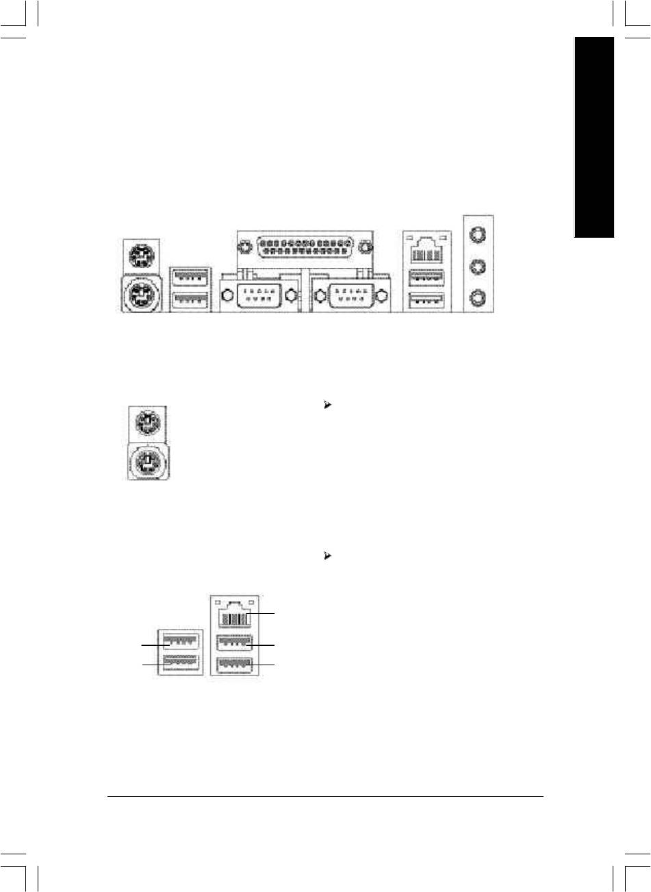
Step 4-1: I/O Back Panel Introduction
y
w
x
u
v
u PS/2 Keyboard and PS/2 Mouse Connector
This connector supports standard PS/2
PS/2 Mouse Connector
keyboard and PS/2 mouse.
(6 pin Female)
PS/2 Keyboard Connector
(6 pin Female)
v/x USB/LAN Connector
Before you connect your device(s) into U SB
connector(s), please make sure your dev ice(s)
such as U SB key board,mouse, scanner, zip,
speaker...etc. Have a standard USB interface.
LAN
Also make sure your OS supports USB controller.
USB 0
USB 2
If your OS does not support USB controller, please
USB 1
USB 3
contact OS v endor for possible patch or driver
upgrade. For more information please contact your
OS or device(s) vendors.
- 17 - Hardware Installation Process
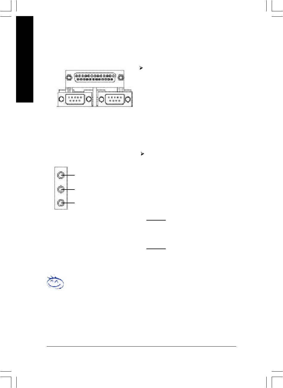
w Parallel Port and Serial Ports (COMA/COMB)
Parallel Port
(25 pin Female)
This connector supports 2 standard COM ports
English
and 1 Parallel port. Device like printer can be
connected to Parallel port ; mouse and modem
etc can be connected to Serial ports.
COMA
COMB
Serial Port (9 pin Male)
y Audio Connectors
After install onboard audio driv er, y ou may
connect speaker to Line Out jack, microphone to
MIC In jack. Device like CD-ROM,walkman etc.
Line In (Rear Speaker)
can be connected to Line-In jack.
Please note:
Line Out (Front Speaker)
You are able to use 2-/4-/6-channel audio feature
by S/W selection.
MIC In (Center and Subwoofer)
If you want to enable 6-channel function, y ou
have 2 choose for hardware connection.
Method1:
Connect "Front Speaker" to "Line Out"
Connect "Rear Speaker" to "Line In"
Connect "Center and Subwoofer" to "MIC Out ".
Method2:
You can refer to page 28, and contact y our
nearest dealer for optional SUR_CEN cable.
If you want the detail information for 2-/4-/6-channel audio setup
installation, please refer to page 67.
- 18 -GA-8IP900MK Motherboard
English
Step 4-2: Connectors Introduction
1 3
11
2
5
6
12
8
4
14
15
21
7
16
19
18
20 22
17
1013
9
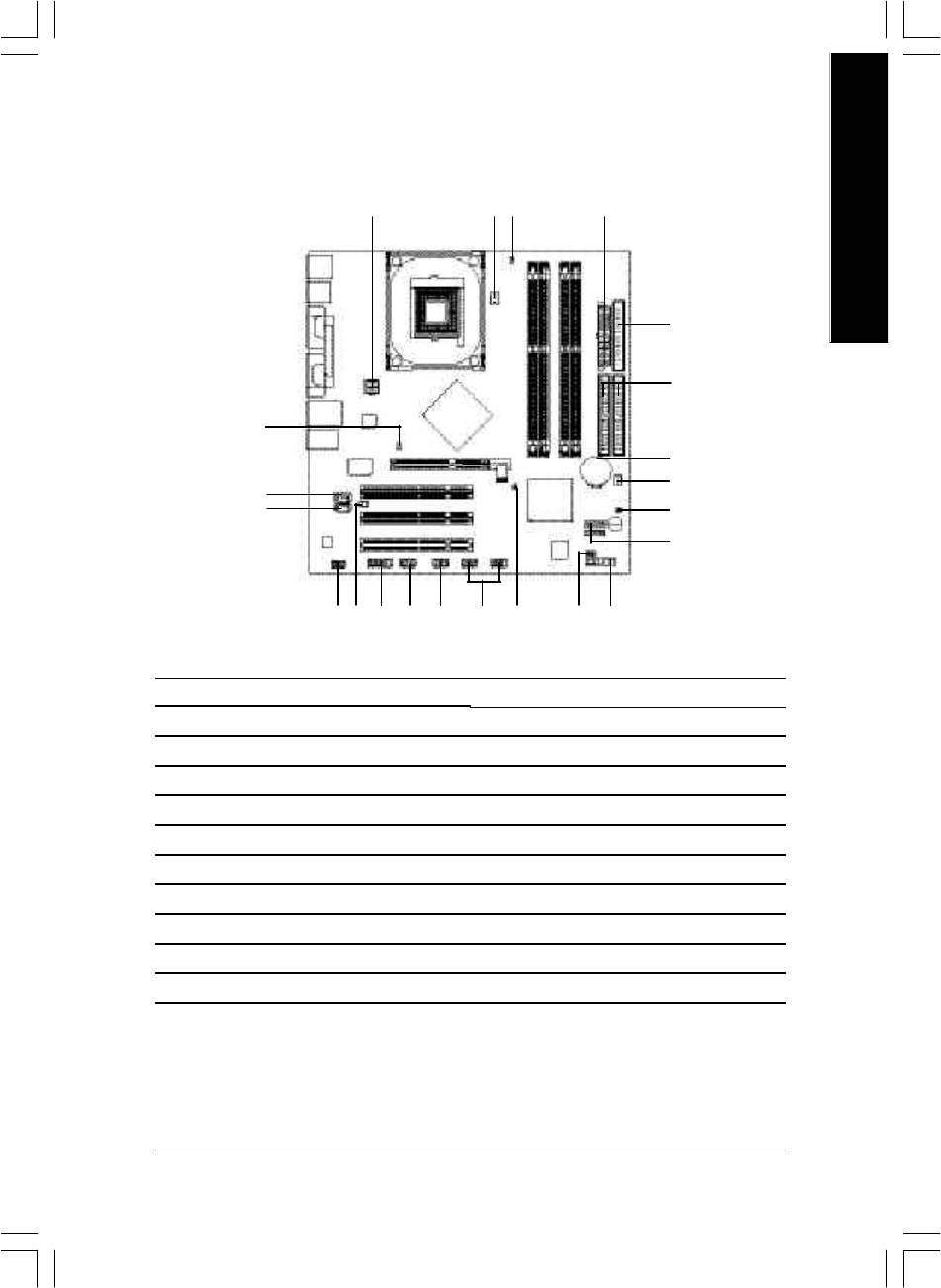
1) ATX_12V
12) 2X_DET
2) ATX
13) F_AUDIO
3) CPU_FAN
14) CD_IN
4) SYS_FAN
15) AUX_IN
5) FDD
16) SUR_CEN
6) IDE1 / IDE2
17) F_USB1 / F_USB2
7) SATA0 / SATA1
18) IR_CIR
8) BAT
19) GAME
9) F_PANEL
20) INFO_LINK
10) PWR_LED
21) CI
11) DIMM_LED
22) CLR_PWD
- 19 - Hardware Installation Process
1) ATX_12V (+12V Power Connector)
This connector (ATX_12V) supplies the CPU operation v oltage (Vcore).
If this "ATX_1 2V connector" is not connected, system cannot boot.
English
Pin No. Definition
1 GND
2
1
2 GND
4
3
3 +12V
4 +12V
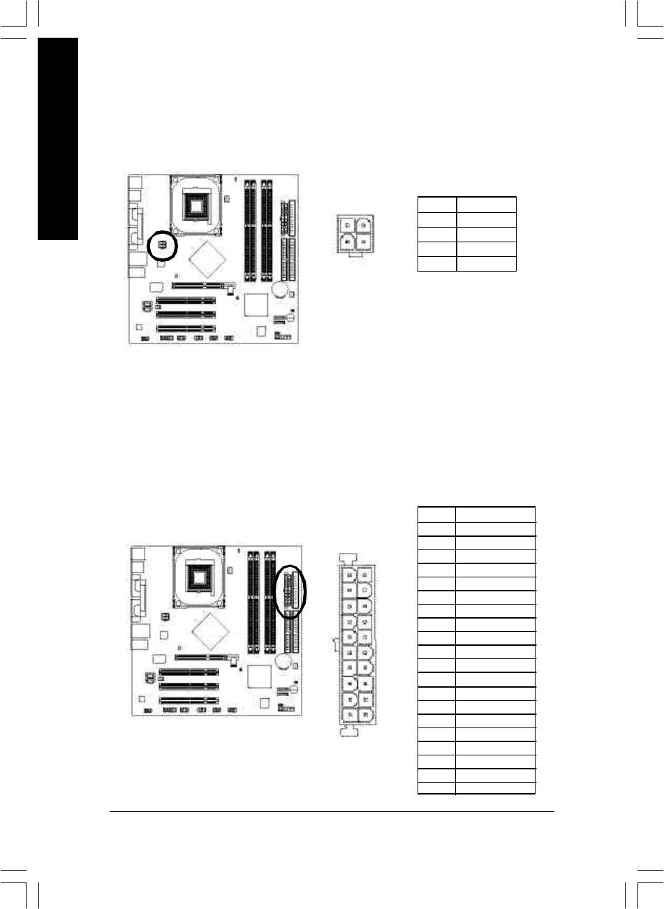
2) ATX (ATX Power)
AC power cord should only be connected to y our power supply unit after ATX pow er cable and
other related d evices are firmly connected to the mainboard.
Pin No. Definition
1 3.3V
2 3.3V
3 GND
4 VCC
11
1
5 GND
6 VCC
7 GND
8 Pow er Good
9 5V SB (stand by +5V)
10 +12V
11 3.3V
12 -12V
13 GND
14 PS_ON(soft on/off)
20
10
15 GND
16 GND
17 GND
18 -5V
19 VCC
20 VCC
- 20 -GA-8IP900MK Motherboard
English
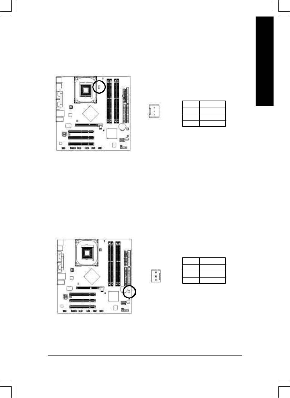
3) CPU_FAN (CPU Fan Connector)
Please note, a proper installation of the CPU cooler is essential to prevent the CPU from ru nning
under abnormal condition or damaged by overheating. The CPU fan conne ctor supports Max.
current up to 60 0 mA.
1
Pin No. Definition
1 GND
2 +12V
3 Sense
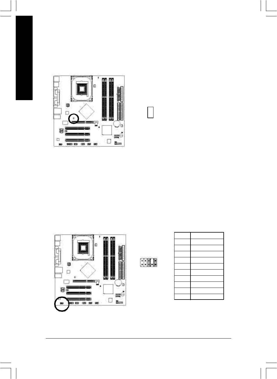
4) SYS_FAN (System Fan Connector)
This connector allows you to link w ith the cooling fan on the system case to lower the sy stem
temperature.
Pin No. Definition
1 GND
2 +12V
3 Sense
1
- 21 - Hardware Installation Process
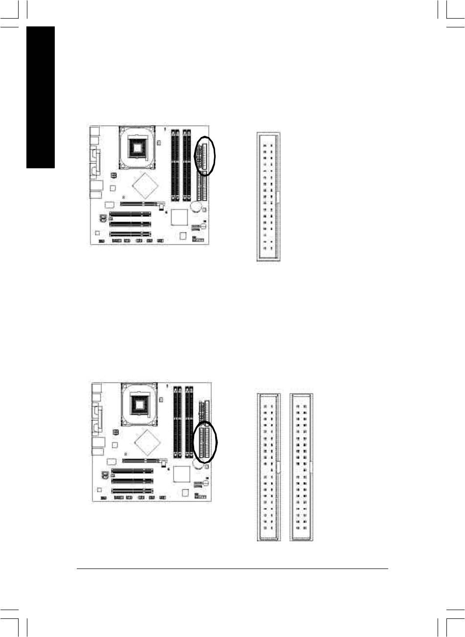
5) FDD (Floppy Connector)
Please connect the flopp y drive ribbon cables to FDD. It supports 360K, 1.2M, 720K, 1.44M and
2.88M bytes floppy disk types.
The red stripe of the ribbon cable must be the same side with the Pin1.
English
34
33
2
1
6) IDE1 / IDE2 (IDE1 / IDE2 Connector)
Important Notice:
Please connect first har d disk to IDE1 and connect CD-ROM to IDE2.
The red stripe of the ribbon cable must be the same side with the Pin1.
3940
12
IDE2
IDE1
- 22 -GA-8IP900MK Motherboard
English
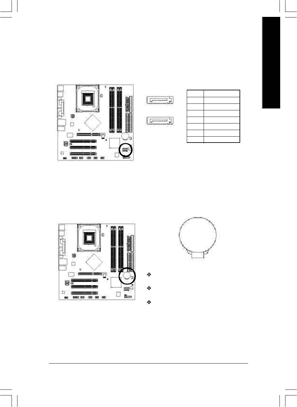
7) SATA0 / S ATA1 (Serial ATA Connector)
You can connect the S erial ATA device to this connector, it provides you high speed transfer rates
(150MB/sec).
Pin No. Definition
7
1
1 GND
SATA1
2 TXP
3 TXN
17
4 GND
5 RXN
SATA0
6 RXP
7 GND
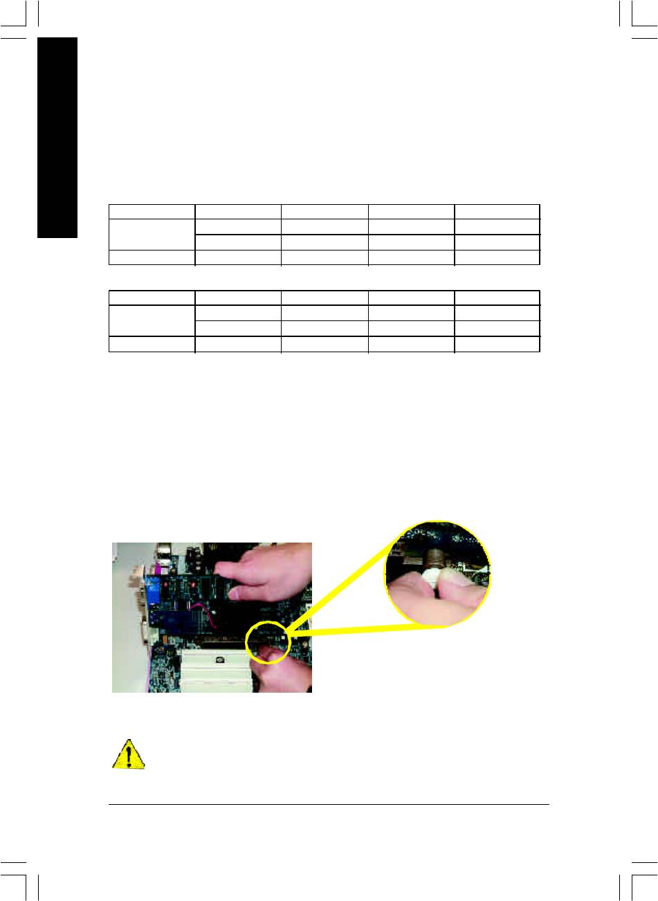
8) BAT (BATTERY)
+
CAUTION
Danger of ex plosion if batter y is incorrectly
replaced.
Replace only w ith the same or equivalent type
recommended by the manufacturer.
Dispose of used batterie s ac cording to the
manufacturer's instructions.
If you want to erase CMOS...
1. Turn OFF the computer and unplug the power cord.
2. Remove the battery , wait for 30 second.
3. Re-install the battery.
4. Plug the pow er cord and turn ON the comp uter.
- 23 - Hardware Installation Process
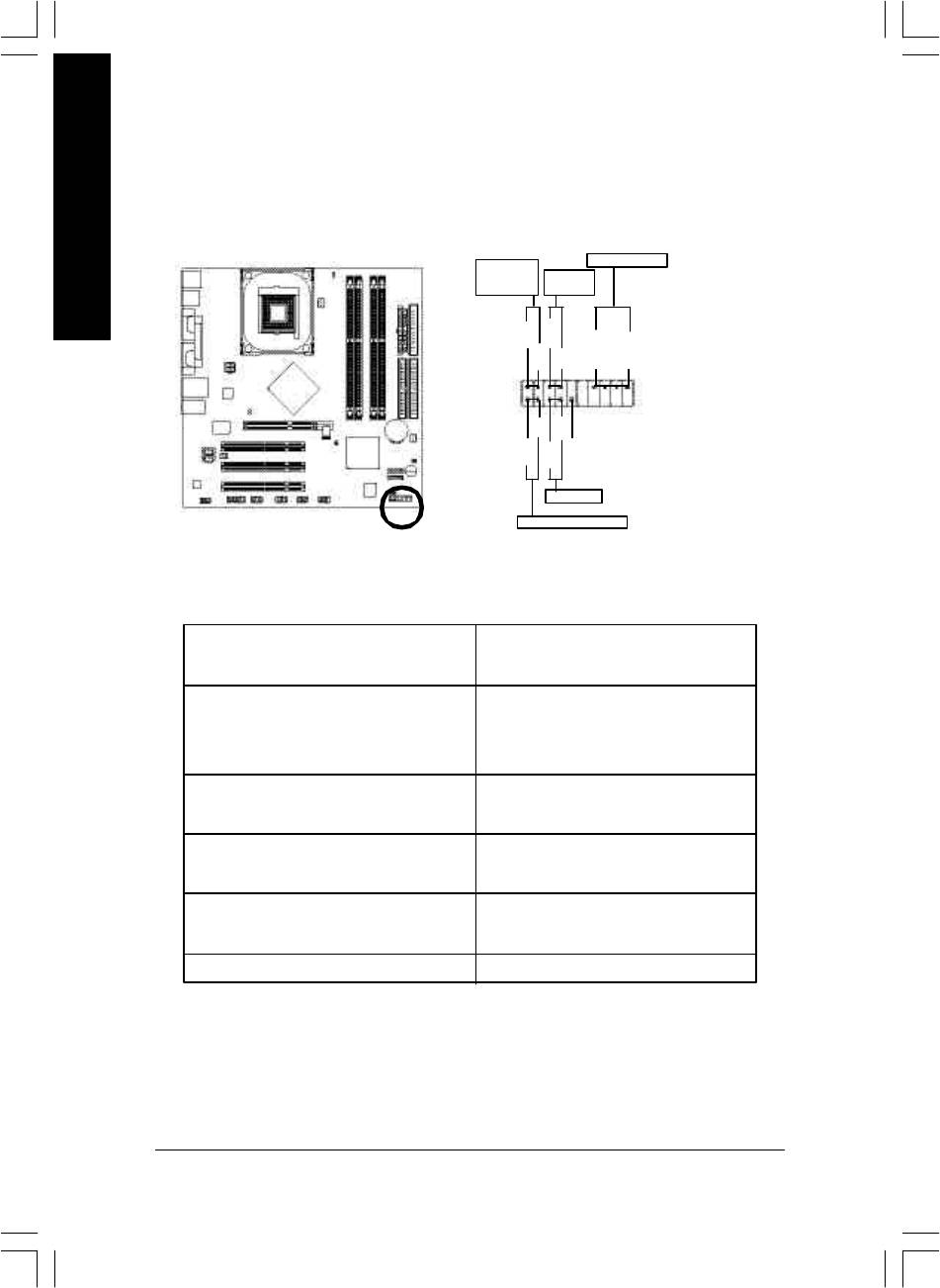
9) F_PANEL (2 x 10 pins Connector)
Please connect the power LED, PC speaker, reset sw itch and power switch etc of your chassisfront
panel to the F_ PANEL connector according to the pin assignment above.
English
Speak er Connector
Messag e LED/
Pow er/
Soft Power
Sleep LED
Conne ctor
PW+
MSG+
MSG-
PW-
SPEAK+
SPEAK-
2
1 1
1
20
1
1 1
19
HD-
RES+
NC
HD+
RES-
Reset Switch
IDE Hard Disk Active LED
HD (IDE Hard Disk Active LED) Pin 1: LED anode(+)
(Blue) Pin 2: LED cathode(-)
SPK (Speaker Connector) Pin 1: VCC(+)
(Amber) Pin 2- Pin 3: NC
Pin 4: Data(-)
RES (Reset Sw itch) Open: Normal Operation
(Green) Close: Reset H ardware System
PW (Soft Power Connector) Open: Normal Operation
(Red) Close: Power On/Off
MSG(Message LED/ Power/ Sleep LED) Pin 1: LED anode(+)
(Yellow) Pin 2: LED cathode(-)
NC (Purple) NC
- 24 -GA-8IP900MK Motherboard
English
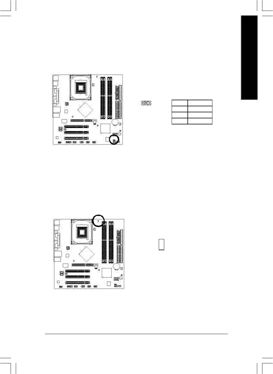
10) PWR_LED
PWR_LED is connect with the sy stem power indicator to indicate whether the system is on/off.
It will blink when the system enters suspend mode. If you use dual color LED, power LED will turn
to another co lor.
1
Pin No. Definition
1 MPD+
2 MPD-
3 MPD-
11) DIMM_LED
Do not remov e memory modules while DIMM_LED is on. It might cause short or other unexpected
damages due to the stand by voltage. Remove memory modules only w hen AC power cord is
disconnected.
_
+
- 25 - Hardware Installation Process
12) 2X_DET
When an AGP 2X (3.3V) card is ins talled the 2X_DET will light u p, indicating a non-supported
graphics card is inserted. Informing users that system might not boot up normall y due to AGP 2X
(3.3V) is not s upported by the chipset.
English
_
+
13) F_AUDIO (Front Audio Connector)
If you want to use Front Audio connector, you must remov e 5-6, 9-10 Jumper.
In order to utilize the front audio header, y our chassis must have front audio connector. Also please
make sure the pin assigm ent on the cable is the same as the pin assigment on the MB header. To
find out if the chassis you are buying support front aud io connector, please contact your dealer.
Please note, y ou can hav e the alternativ e of using front audio connector or of using rear audio
connector to play sound.
Pin No. Definition
1 MIC
2 GND
2
10
3 REF
4 Pow er
5 Fron t Audio (R)
1
9
6 Rear Audio (R)
7 Rese rved
8 No Pin
9 Fron t Audio (L)
10 Rear Audio (L)
- 26 -GA-8IP900MK Motherboard
English
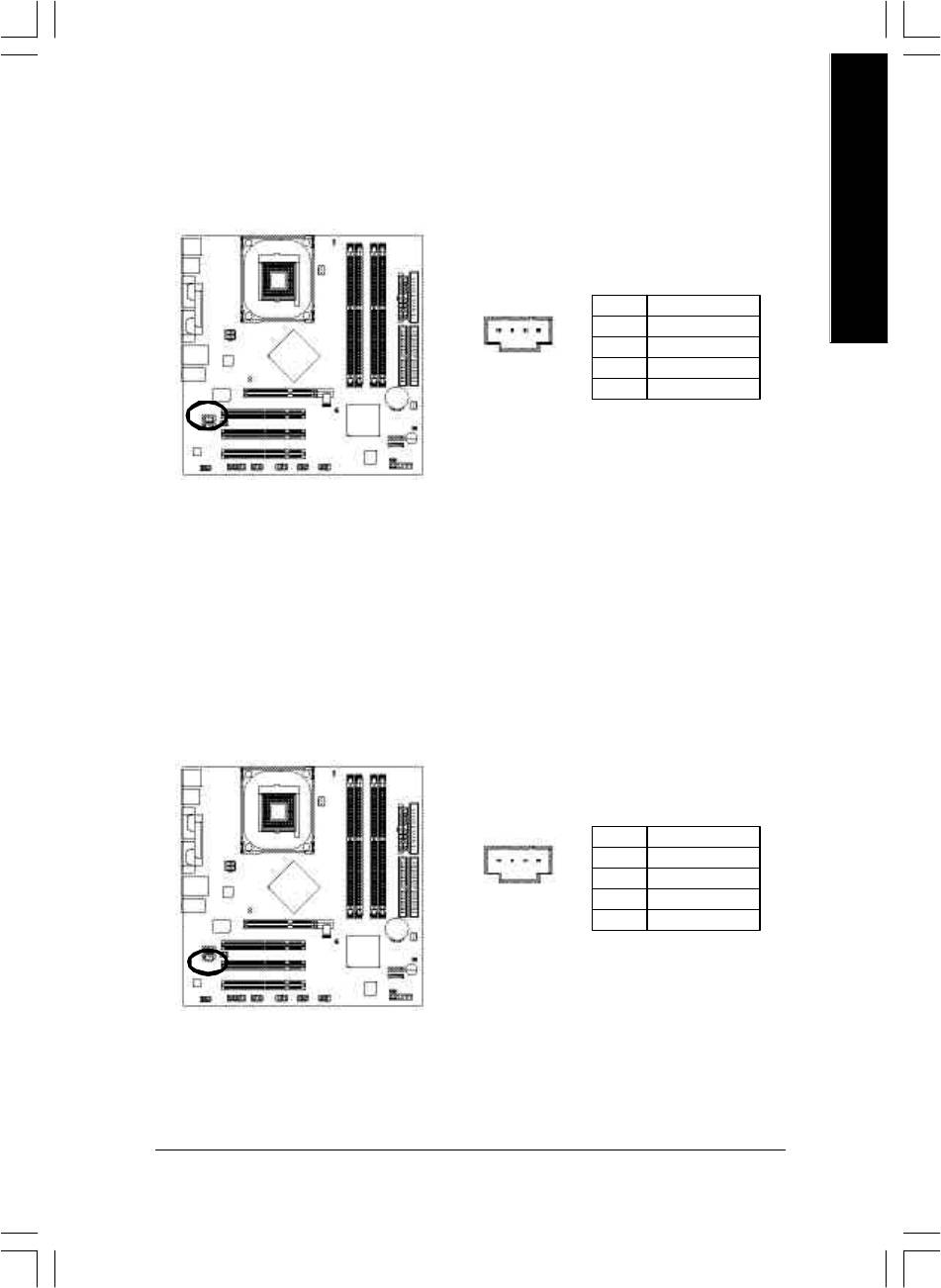
14) CD_IN (CD In Connector)
Connect CD-ROM or DVD-ROM audio out to the connector.
Pin No. Definition
1 CD-L
1
2 GND
3 GND
4 CD-R
15) AUX_IN (AUX In Connector)
Connect other device (such as PCI TV Tunner audio out) to the connector.
Pin No. Definition
1 AUX-L
1
2 GND
3 GND
4 AUX-R
- 27 - Hardware Installation Process
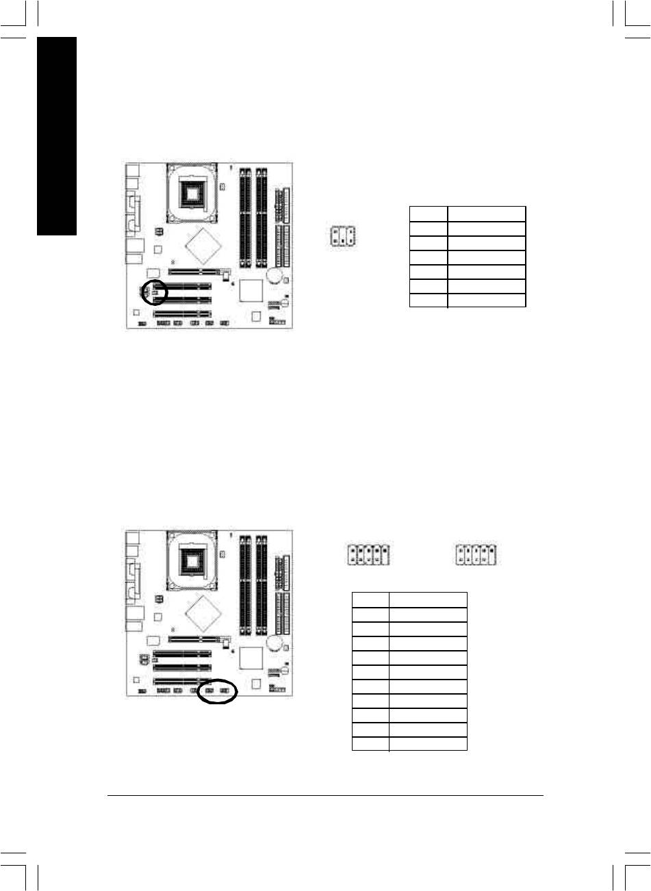
16) SUR_CEN (Surround Center Connector)
Please contact y our nearest dealer for optional SUR_CEN cable.
English
Pin No. Definition
2
6
1 SUR OUTL
2 SUR OUTR
1
5
3 GND
4 No Pin
5 CENTE R_OUT
6 BASS _OUT
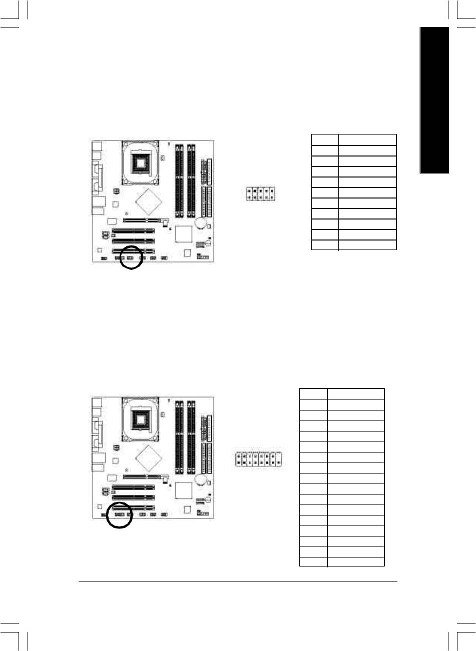
17) F_USB1 / F_USB2 (Front USB Connector, Yellow)
Be careful with the polarity of the fr ont USB connector. Check the pin assignment while y ou
connect the fr ont USB cable. Please contact your nearest dealer for optional front USB c able.
2 10
2 10
F_USB1
F_USB2
1 9
1 9
Pin No. Definition
1 Pow er
2 Pow er
3 USB Dx-
4 USB Dy-
5 USB Dx+
6 USB Dy+
7 GND
8 GND
9 No Pin
10 NC
- 28 -GA-8IP900MK Motherboard
English
18) IR_CIR
Make sure the pin 1 on the IR device is aling w ith pin one the connector. To enable the IR/CIR
function on the board, y ou are required to purchase an option IR/CIR module. For detail information
please contact your autherized Gigabyte distributor. To use IR function only, please connect IR
module to Pin1 to Pin5.
Pin No. Definition
1 VCC
2 NC
3 IRRX
6 10
4 GND
5 IRTX
6 NC
1 5
7 CIRRX
8 +5VSB
9 CIRTX
10 NC
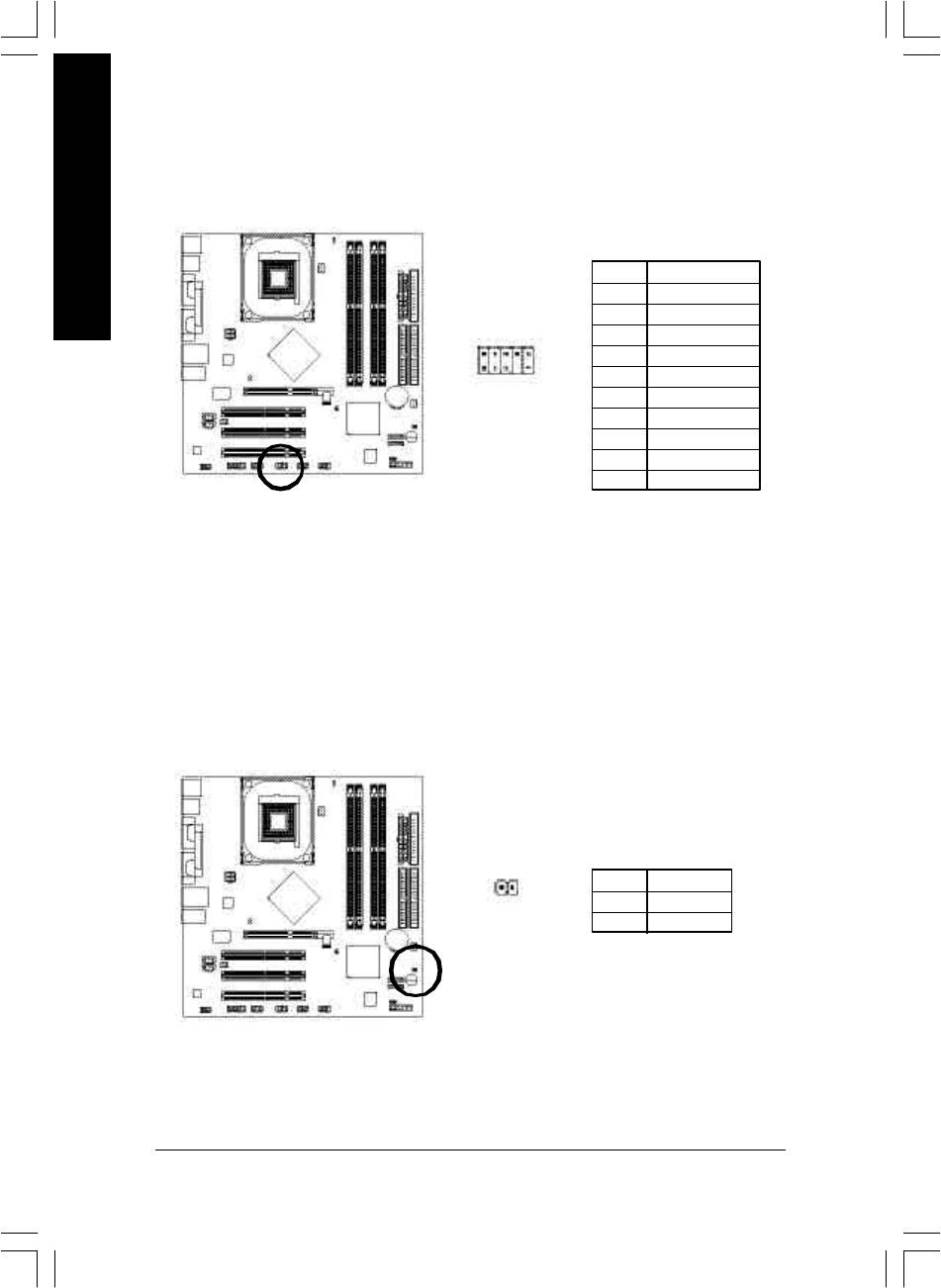
19) GAME (Game Connector)
This connector supports joystick, MIDI keyboard and other relate audio dev ices.
Pin No. Definition
1 VCC
2 GRX 1_R
3 GND
4 GPSA2
2
16
5 VCC
6 GPX 2_R
7 GPY 2_R
1
15
8 MSI_R
9 GPSA1
10 GND
11 GPY1_R
12 VCC
13 GPSB1
14 MSO_R
15 GPSB2
16 No Pin
- 29 - Hardware Installation Process
20) INFO_LINK
This connector allows y ou to connect some external devices to provide you extra function.
English
Pin No. Definition
1 SMB CLK
2 VCC
102
3 SMBD ATA
4 GPIO
5 GND
1
9
6 GND
7 No Pin
8 NC
9 +12V
10 +12V
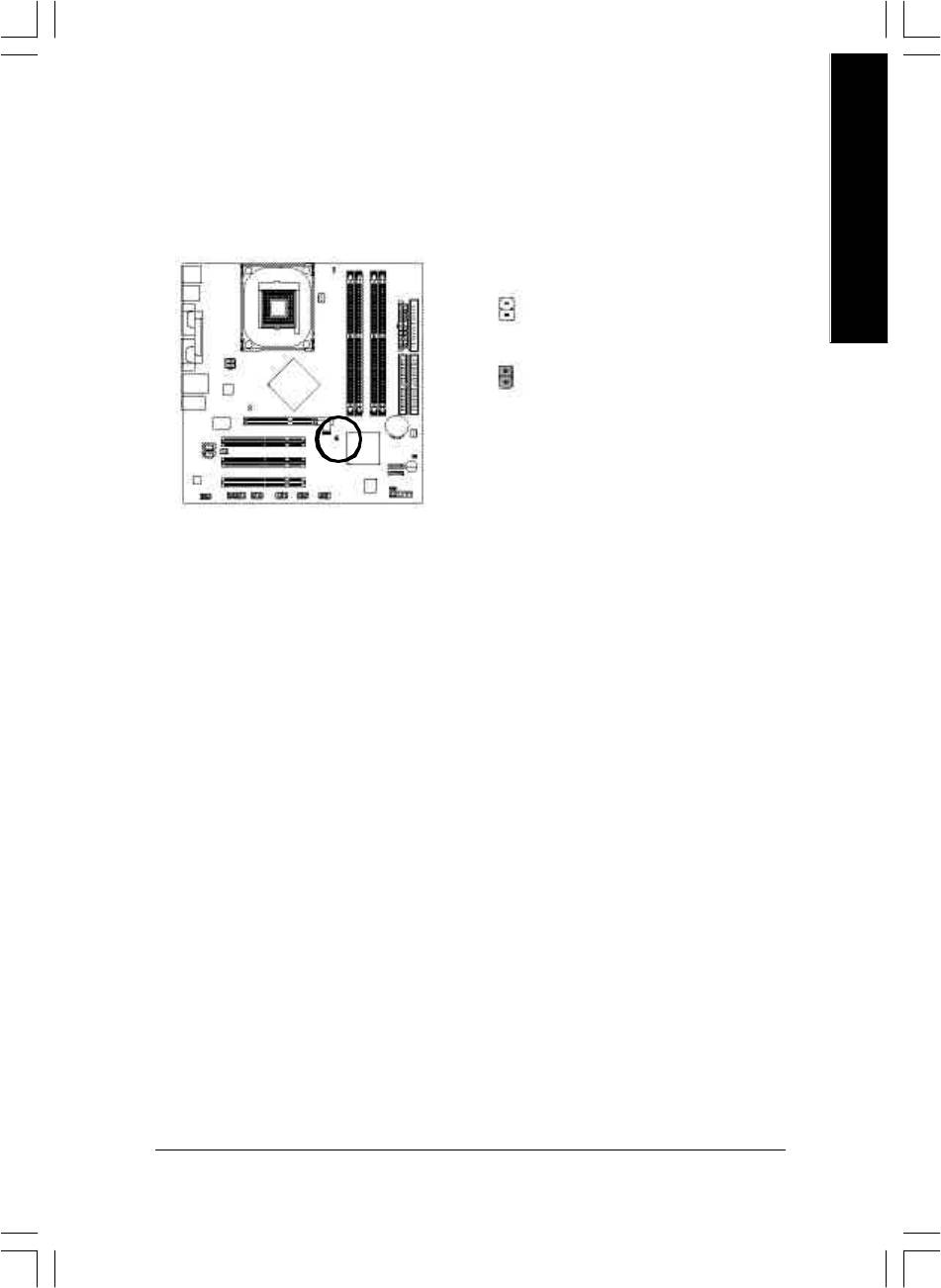
21) CI (CAS E OPEN)
This 2-pin connector allo ws your system to enable or disable the "Case Open" item in BIOS, if the
syste m case begin remove.
Pin No. Definition
1
1 Sig nal
2 GND
- 30 -GA-8IP900MK Motherboard
English
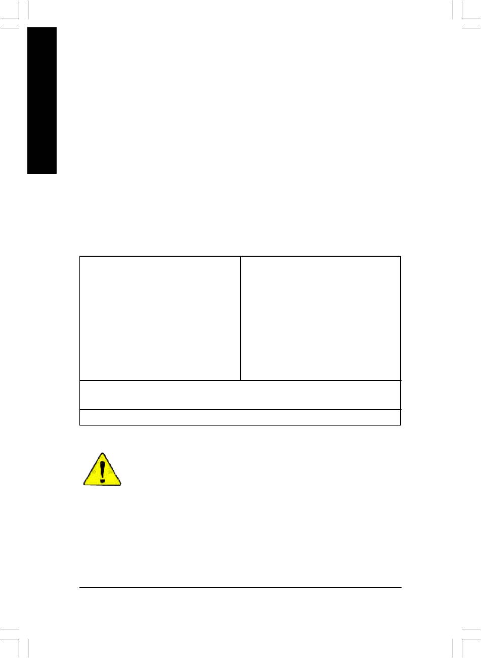
22) CLR_PWD
When Jumper is set to "open" and system is restarted, the passw ord that is set w ill be cle ared.
On the contrar y when Jumper is set to "close", the current status remains.
Open: Clear Password
1
Close: Normal
1
- 31 - Hardware Installation Process

English
- 32 -GA-8IP900MK Motherboard

English
Chapter 3 BIOS Setup
BIOS Setup is an overview of the BIOS Setup Program. The program that allows users to modify the
basic system configuration. This type of information is stored in battery-backed CMOS RAM so that it
retains the Setup information when the power is turned off.
ENTERING
SETUP
Powering ON the computer and pressing <Del> immediately will allow you to enter Setup. If you require
more advanced BIOS settings, please go to "Advanced BIOS" setting menu. To enter Advanced BIOS
setting menu, press "Ctrl+F1" key on the BIOS screen.
CONTROL
KEYS
<á> Move to previous item
<â> Move to next item
<ß> Move to the item in the left hand
<à> Move to the item in the right hand
Enter Select item
<Esc> Main Menu - Quit and not save changes into CMOS Status Page Setup Menu and
Option Page Setup Menu - Exit current page and return to Main Menu
<+/PgUp> Increase the numeric value or make changes
<-/PgDn> Decrease the numeric value or make changes
<F1> General help, only for Status Page Setup Menu and Option Page Setup Menu
<F2> Item Help
<F3> Reserved
<F4> Reserved
<F5> Restore the previous CMOS value from CMOS, only for Option Page Setup Menu
<F6> Load the file-safe default CMOS value from BIOS default table
<F7> Load the Optimized Defaults
<F8> Q-Flash function
<F9> System Information
<F10> Save all the CMOS changes, only for Main Menu
- 33 - BIOS Setup
8ip900mk_1001_b.p65 2003/4/22, 下午 03:5433
GETTING HELP
Main Menu
The on-line description of the highlighted setup function is displayed at the bottom of the screen.
English
Status Page Setup Menu / Option Page Setup Menu
Press F1 to pop up a small help window that describes the appropriate keys to use and the possible
selections for the highlighted item. To exit the Help Window press <Esc>.
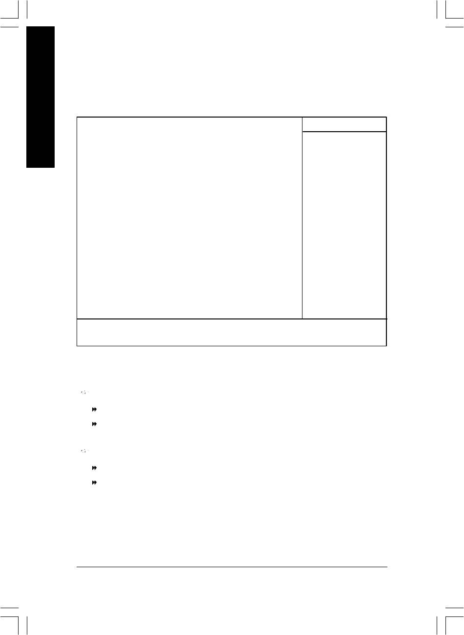
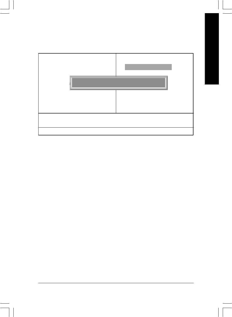
The Main Menu (For example: BIOS Ver. : F2 )
Once you enter Award BIOS CMOS Setup Utility, the Main Menu (Figure 1) will appear on the screen.
The Main Menu allows you to select from eight setup functions and two exit choices. Use arrow keys to
select among the items and press <Enter> to accept or enter the sub-menu.
CMOS Setup Util ity-Copyright (C) 1984-2003 Award Software
} Standard CMOS Features
Load Fail-Safe De faults
} Advanced BIOS Fe atures
Load Optimized De faults
} Integrated Peripherals
Set Supervisor Password
} Power Management Setup
Set User Password
} PnP/PCI Configurations
Save & Exit Setup
} PC Health Status
Exit Without Saving
} Frequency/Vol tage Control
ESC: Quit higf: Select Item
F8: Q-Flash F10: Save & Exit Setup
Time, Date, Har d Disk Ty pe...
Figure 1: Main Menu
If you can't find the setting you want, please press "Ctrl+F1" to
search the advanced option widden.
l Standard CMOS Features
This setup page includes all the items in standard compatible BIOS.
l Advanced BIOS Features
This setup page includes all the items of Award special enhanced features.
- 34 -GA-8IP900MK Motherboard
8ip900mk_1001_b.p65 2003/4/22, 下午 03:5434

English
l Integrated Peripherals
This setup page includes all onboard peripherals.
l Power Management Setup
This setup page includes all the items of Green function features.
l PnP/PCI Configurations
This setup page includes all the configurations of PCI & PnP ISA resources.
l PC Health Status
This setup page is the System auto detect Temperature, voltage, fan, speed.
l Frequency/Voltage Control
This setup page is control CPU’s clock and frequency ratio.
l Load Fail-Safe Defaults
Fail-Safe Defaults indicates the value of the system parameters which the system would
be in safe configuration.
l Load Optimized Defaults
Optimized Defaults indicates the value of the system parameters which the system would
be in best performance configuration.
l Set Supervisor password
Change, set, or disable password. It allows you to limit access to the system and Setup,
or just to Setup.
l Set User password
Change, set, or disable password. It allows you to limit access to the system.
l Save & Exit Setup
Save CMOS value settings to CMOS and exit setup.
l Exit Without Saving
Abandon all CMOS value changes and exit setup.
- 35 - BIOS Setup
8ip900mk_1001_b.p65 2003/4/22, 下午 03:5435

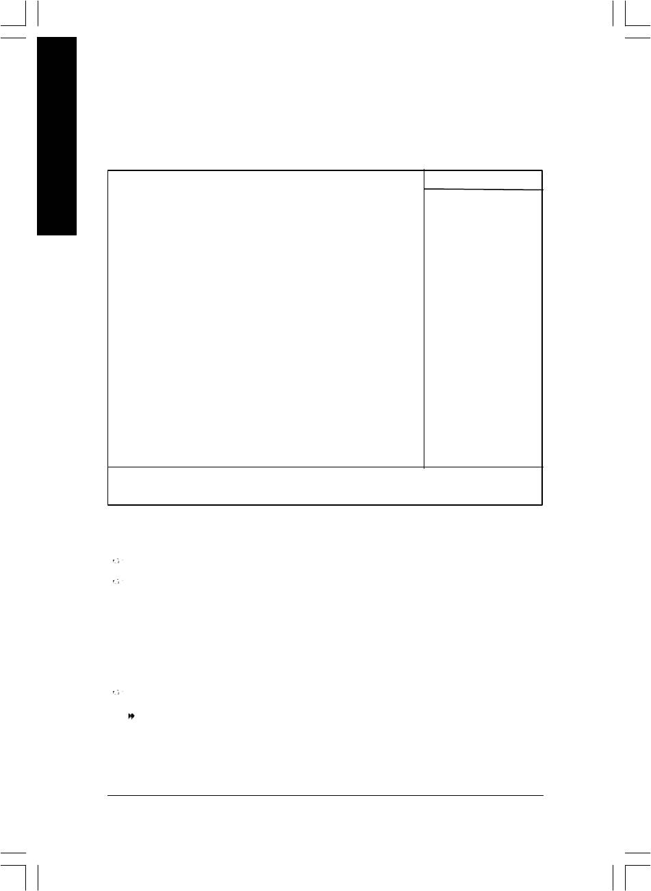
Standard CMOS Features
CMOS Setup Util ity-Copyright (C) 1984-2003 Award Software
Standard CMOS Features
English
Date (mm:dd:yy) Sat, Mar 22 2003 Item Help
Time (hh:mm:ss) 22:31:24 Menu Level u
Change the day , month,
}IDE Primary Master [None] year
}IDE Primary Slave [None]
}IDE Secondary Master [None] <Week>
}IDE Secondary Slave [None] Sun. to Sat.
Drive A [1.44M, 3.5"] <Month>
Driv e B [None] Jan. to Dec.
Floppy 3 Mode Support [Disabled]
<Day>
Halt On [All, But Keyboard] 1 to 31 (or maximum
allowed in the month)
Base Memory 640K
Exte nded Memory 111M <Year>
Total Memory 112M 1999 to 2098
higf: Mov e Enter:Select +/-/PU/PD:Value F10:Sav e ESC:Exit F1:General Help
F5:Previous Values F6:Fail-Safe Defaults F7:Optimized Defaults
Figure 2: Standard CMOS Features
Date
The date format is <week>, <month>, <day>, <year>.
Week The w eek, from Sun to Sat, determined by the BIOS and is display only
Month The month, Jan . Through Dec.
Day The day, from 1 to 31 (or the maximum allowed in the month)
Year The year, from 1999 through 2098
- 36 -GA-8IP900MK Motherboard
8ip900mk_1001_b.p65 2003/4/22, 下午 03:5436

English
Time
The times format in <hour> <minute> <second>. The time is calculated base on the 24-hour
military-time clock. For ex ample, 1 p.m. is 13:00:00.
IDE Primary Master, Slave / IDE Secondary Master, Slave
The category identifies the ty pes of hard disk from driv e C to F that ha s been installed in the
computer. There are tw o types: auto type, and manual type. Manual type is user-definable; Auto ty pe
which will automatically detect HDD type.
Note that the specific ations of your drive must match with the drive table. The hard disk w ill not work
properly if y ou enter improper information for this category.
If you select User Type, relate d information will be asked to enter to the follow ing items. Enter the
information direc tly from the keyboard and press <Enter>. Such information should be prov ided in the
documentation form y our hard disk vendor or the system manufacturer.
CYLS. Number of cy linders
HEADS Number of h eads
PRECOMP Write precomp
LANDZONE Landing zone
SECTORS Number of sec tors
If a hard disk has not been installed select NONE and press <Enter>.
Drive A / Drive B
The catego ry identifies the types of floppy disk drive A or driv e B that has been installed in the
computer.
None No floppy drive installed
360K, 5.25" 5.25 inch PC-type standard driv e; 360K byte capacity.
1.2M, 5.25" 5.25 inch AT-type high-density drive; 1.2M by te capacity
(3.5 inch when 3 Mode is Enabled).
720K, 3.5" 3.5 inch double-sided drive; 720K byte capacity
1.44M, 3.5" 3.5 inch double-sided drive; 1.44M byte capacity .
2.88M, 3.5" 3.5 inch double-sided drive; 2.88M byte capacity .
- 37 - BIOS Setup
8ip900mk_1001_b.p65 2003/4/22, 下午 03:5437

Floppy 3 Mode Support (for Japan Area)
Disabled Normal Floppy Drive. (Default v alue)
Driv e A Drive A is 3 mode Floppy Drive.
English
Driv e B Drive B is 3 mode Floppy Drive.
Both Drive A & B are 3 mode Floppy Drives.
Halt on
The category determines whether the computer will stop if an error is detected during pow er up.
NO Errors The system boot will not stop for any error that may be detected and you
will be prompted.
All Errors Whenever the BIOS detects a non-fatal error the sy stem boot will be stopped.
All, But Key board The system boot will not stop for all errors except a keyboard error.
(Default value)
All, But Disk ette The system boot will not stop for all errors except a disk e rror.
All, But Disk /Key The system boot will not stop for all errors except keyboard and disk errors.
Memory
The category is display-only which is determined by POST (Power On Self Test) of the BIOS.
Base Memory
The POST of the B IOS will determine the amount of base (or conventional) memory installed
in the system.
The value of the base memory is ty pically 512 K for systems with 512K memory installed on
the motherboard, o r 640 K for systems with 640 K or more memory installed on the motherboard.
Extended Memory
The BIOS deter mines how much ex tended memory is present during the POST.
This is the am ount of memory located above 1MB in the CPU's memory address map.
- 38 -GA-8IP900MK Motherboard
8ip900mk_1001_b.p65 2003/4/22, 下午 03:5438
English
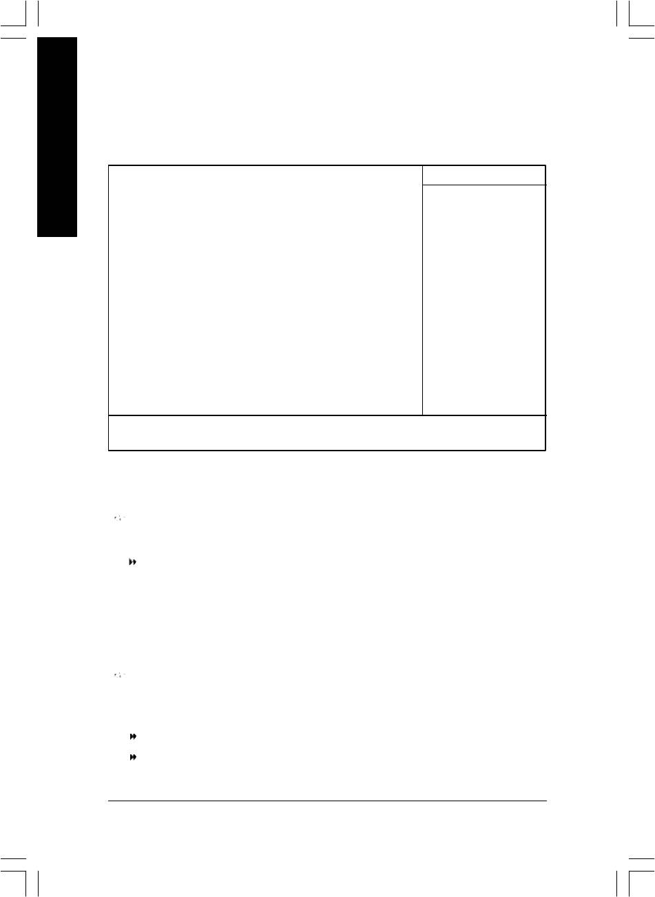
Advanced BIOS Features
CMOS Setup Util ity-Copyright (C) 1984-2003 Award Software
Advanced BIOS Features
First Boot Device [Floppy]
Item Help
Second Boot Dev ice [HDD-0]
Menu Level u
Third Boot De vice [CDROM]
Select Boot Dev ice
Password Check [Setup]
Priority
# CPU Hyper-Threading [Enabled]
[Floppy]
Boot from floppy
[LS120]
Boot from LS120
higf: Mov e Enter:Select +/-/PU/PD:Value F10:Sav e ESC:Exit F1:General Help
F5:Previous Values F6:Fail-Safe Defaults F7:Optimized Defaults
Figure 3: Advanced BIOS Features
®
®
" # " System will detect automatically and show up when you install the Intel
Pentium
4 processor with
HT Technology.
First / Second / Third Boot Device
Floppy Select your boot device priority by Floppy.
LS120 Select your boot device priority by LS120.
Hard Disk Select y our boot device priority by Hard Disk.
CDROM Select y our boot device priority by CDROM.
ZIP Select y our boot device priority by ZIP.
USB-FDD Select y our boot device priority by USB-FDD.
USB-ZIP Select y our boot device priority by USB-ZIP.
USB-CDROM Selec t your boot device priority by USB-CDROM.
USB-HDD Select y our boot device priority by USB-HDD.
LAN Select y our boot device priority by LAN.
Disabled Select y our boot device priority by Disabled.
- 39 - BIOS Setup
8ip900mk_1001_b.p65 2003/4/22, 下午 03:5439

Password Check
Setup The system will boot but will not access to Setup page if the correct
passw ord is not entered at the prompt. (Default v alue)
System The system will not boot and will not access to Se tup page if the correct
English
passw ord is not entered at the pr ompt.
#
CPU Hyper-Threading
Enabled Enables CPU Hyper Threading Feature. Please note that this fe ature is only
working for operating sy stem with multi processors mode supported.
(Default value)
Disabled Disables CPU Hy per Threading.
" # " System will detect automatically and show up when you install the Intel
®
Pentium
®
4 processor with HT Technology.
- 40 -GA-8IP900MK Motherboard
8ip900mk_1001_b.p65 2003/4/22, 下午 03:5440

English
Integrated Peripherals
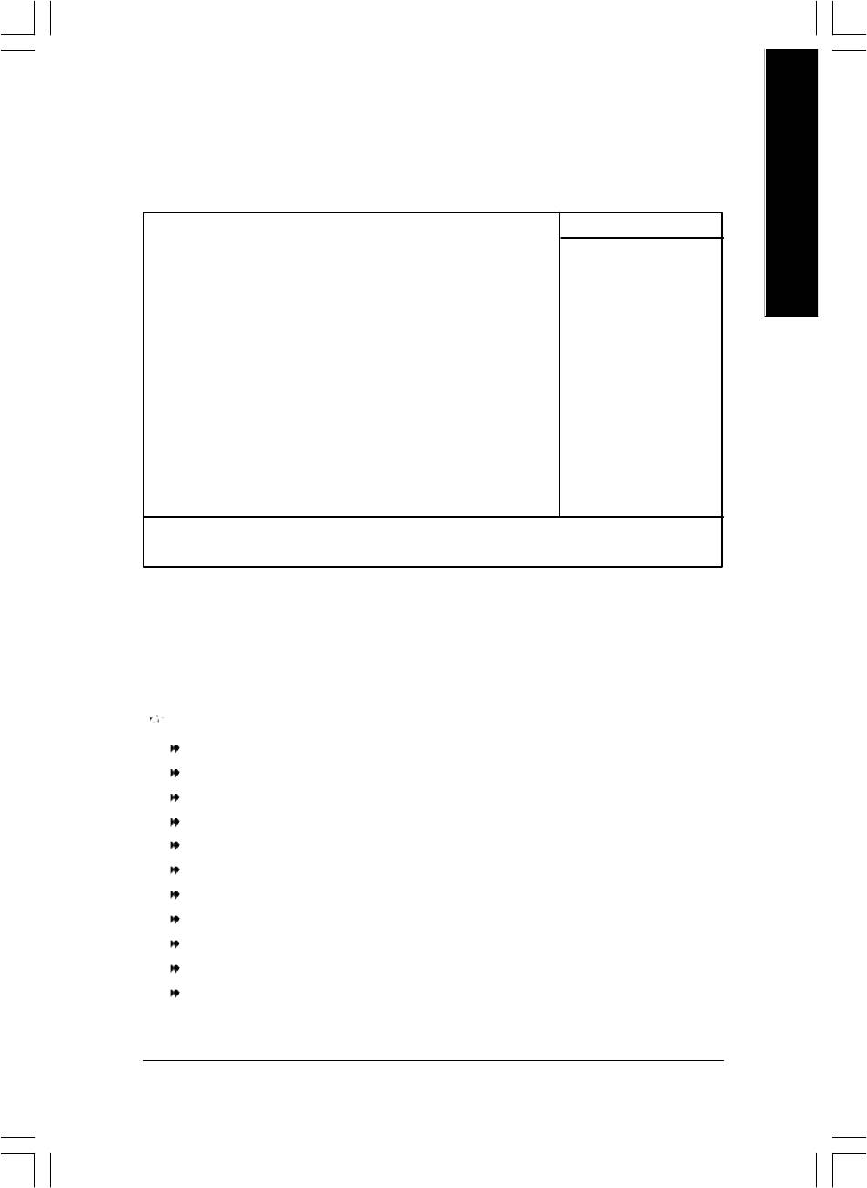
CMOS Setup Util ity-Copyright (C) 1984-2003 Award Software
Integrated Perip herals
On-Chip Primary PCI IDE [Enabled]
Item Help
On-Chip Secondary PCI IDE [Enabled]
Menu Level u
On-Chip SATA [Auto]
If a hard disk
x SATA Port0 Configure as SATA Port0
controller card is
SATA Port1 Config ure as SATA Port1
used, set at Dis abled
USB Controller [Enabled]
USB 2.0 Contr oller [Enabled]
[Enabled]
USB Keyboard Support [Disabled]
Enabled onboard IDE
USB Mouse Support [Disabled]
Port
AC97 Audio [Auto]
Onboard H/W LAN [Enabled]
[Disabled]
Onboard Serial Port 1 [3F8/IRQ4]
Disabled onboard IDE
Onboard Serial Port 2 [2F8/IRQ3]
Port
UART Mode Select [Normal]
x UR2 Duplex Mode Half
Onboard Parallel Port [378/IRQ7]
Parallel Port Mode [SPP]
x ECP Mode Use DMA 3
Game Port Add ress [201]
Midi Port Add ress [330]
Midi Port IRQ [10]
higf: Mov e Enter:Select +/-/PU/PD:Value F10:Sav e ESC:Exit F1:General Help
F5:Previous Values F6:Fail-Safe Defaults F7:Optimized Defaults
Figure 4: Integrated Peripherals
- 41 - BIOS Setup
8ip900mk_1001_b.p65 2003/4/22, 下午 03:5441

On-Chip Primary PCI IDE
Enabled Enable onboard 1st channel IDE port. (Default v alue)
Disabled Disable onboard 1st channel IDE port.
English
On-Chip Secondary PCI IDE
Enabled Enable onboard 2nd channel IDE port. (Default v alue)
Disabled Disable onboard 2nd channel IDE port.
On-chip SATA
Disabled Disable SATA controller.
Auto When there is no dev ice to be plugged in IDE1 or IDE2, SATA controller will
remap to IDE co ntroller. (Default Value)
Manual Set SATA Mod e manually.
SATA Port0 Configure as
This item w ill available when "On-chip SATA" set at "Manual".
IDE Pri. Master Remap SATA Port 0 to IDE Pri. Master.
IDE Pri. Slave Remap SATA Por t 0 to IDE Pri. Slave.
IDE Sec. Master Remap SATA Port 0 to IDE Sec. Master.
IDE Sec. Slave Remap SATA Port 0 to IDE Sec. Slave.
SATA Port0 SATA controlle r set to SATA port0. As this mode, it support by WinXP or
later OS only. (Default v alue)
SATA Port1 SATA controlle r set to SATA port1. As this mode, it support by WinXP or
later OS only.
SATA Port1 Configure as
The values depend on SATA Port0.
USB Controller
Enabled Enable USB Controller. (Default v alue)
Disabled Disable USB Contr oller.
- 42 -GA-8IP900MK Motherboard
8ip900mk_1001_b.p65 2003/4/22, 下午 03:5442

English
USB 2.0 Controller
Disable this fu nction if you are not using onboard USB 2.0 feature.
Enabled Enable USB 2.0 Controller. (Default v alue)
Disabled Disable USB 2.0 Controller.
USB Keyboard Support
Enabled Enable USB Key board Support.
Disabled Disable USB Keyboard Support. (Default v alue)
USB Mouse Support
Enabled Enable USB Mouse Support.
Disabled Disable USB Mouse Support. (Default v alue)
AC97 Audio
Auto Auto detect AC' 97 audio function. (Default Value)
Disabled Disable AC'97 audio function.
Onboard H/W LAN
Enabled Enable Onboard H/W LAN function. (Default v alue)
Disabled Disable this fun ction.
Onboard Serial Port 1
Auto BIOS will automatically setup the port 1 address.
3F8/IRQ4 Enable onboard Serial port 1 and address is 3F8. (Default v alue)
2F8/IRQ3 Enable onboard Serial port 1 and address is 2F8.
3E8/IRQ4 Enable onboard Serial port 1 and address is 3E8.
2E8/IRQ3 Enable onboard Serial port 1 and address is 2E8.
Disabled Disable onboard Serial port 1.
- 43 - BIOS Setup
8ip900mk_1001_b.p65 2003/4/22, 下午 03:5443

Onboard Serial Port 2
Auto BIOS will automatically setup the port 2 address.
3F8/IRQ4 Enable onboard Serial port 2 and address is 3F8.
English
2F8/IRQ3 Enable onboard Serial port 2 and address is 2F8. (Default v alue)
3E8/IRQ4 Enable onboard Serial port 2 and address is 3E8.
2E8/IRQ3 Enable onboard Serial port 2 and address is 2E8.
Disabled Disable onboard Serial port 2.
UART Mode Select
This item allo ws you to determine which Infra Red(IR) function of Onboard I/O chip.
Normal Set onboard I/O chip UART to Normal Mode. (Default Value)
IrDA Set onboard I/O chip UART to IrDA Mode.
ASKIR Set onboard I/O chip UART to ASKIR Mode.
SCR Set onboard I/O chip UART to SCR Interface.
UR2 Duplex Mode
This feature allows you to seclect IR mode.
This function will available when "UART Mode Select" doesn't set a t Normal/SCR.
Half IR Function Dup lex Half. (Default Value)
Full IR Function Duplex Full.
Onboard Parallel port
This feature allows you to select from a given set of parameters if the parallel port uses the onboard
I/O control ler.
Disabled Disable onboard LPT port.
378/IRQ7 Enable onboard LPT port and address is 378/IRQ7. (Default Value)
278/IRQ5 Enable onboard LPT port and address is 278/IRQ5.
3BC/IRQ7 Enable onboard LPT port and address is 3BC/IRQ7.
Parallel Port Mode
This feature a llows you to connect with an advanced printe r via the port mode it supports.
SPP Using Parallel port as Standard Parallel Port. (Default Value)
EPP Using Parallel port as Enhanced Parallel Port.
ECP Using Parallel port as Ex tended Capabilities Port.
ECP+EPP Using Parallel port as ECP & EPP mode.
- 44 -GA-8IP900MK Motherboard
8ip900mk_1001_b.p65 2003/4/22, 下午 03:5444

English
ECP Mode Use DMA
This feature allow s you to select Direct Memory Access(DMA) channel if the ECP mode selected.
This function w ill available w hen "Parallel Port Mode" set at ECP or ECP+EPP.
3 Set ECP Mode Use DMA to 3. (Default Value)
1 Set ECP Mode Use DMA to 1.
Game Port Address
201 Set Game Port Address to 201. (Default Value)
209 Set Game Port Address to 209.
Disabled Disable this fun ction.
Midi Port Address
300 Set Midi Port Address to 300.
330 Set Midi Port Address to 330.(Default Value)
Disabled Disable this fun ction.
Midi Port IRQ
5 Set Midi Port IRQ to 5.
10 Set Midi Port IRQ to 10. (Default Value)
- 45 - BIOS Setup
8ip900mk_1001_b.p65 2003/4/22, 下午 03:5445
Power Management Setup
CMOS Setup Util ity-Copyright (C) 1984-2003 Award Software
Power Management Setup
English
ACPI Suspend Type [S1(POS)]
Item Help
Power LED in S1 state [Blinking]
Menu Level u
Off by Power button [Instant-off]
[S1]
PME Event Wake Up [Enabled]
Set suspend ty pe to
ModemRingOn/Wake OnLan [Enabled]
Power On Su spend under
Resume by Alarm [Disabled]
ACPI OS
x Date (of Month) Alarm Everyday
x Time (hh:mm:ss) Alarm 0 : 0 : 0
[S3]
Power On by Mouse [Disabled]
Set suspend ty pe to
Power On by Key board [Disabled]
Suspend to RAM under
x KB Power ON Pas sword Enter
ACPI OS
AC Back Function [Soft-Off]
higf: Mov e Enter:Select +/-/PU/PD:Value F10:Sav e ESC:Exit F1:General Help
F5:Previous Values F6:Fail-Safe Defaults F7:Optimized Defaults
Figure 5: Power Management Setup
ACPI Suspend Type
S1(POS) Set A CPI suspend type to S1. (Default Value)
S3(STR) Set A CPI suspend type to S3.
Power LED in S1 state
Blinking In standby mode(S1), pow er LED will blink. (Default Value)
Dual/OFF In standby mode(S1):
a. If use single color LED, power LED w ill turn off.
b. If use dual color LED, power LED will turn to another color.
- 46 -GA-8IP900MK Motherboard
8ip900mk_1001_b.p65 2003/4/22, 下午 03:5546

English
Off by Power button
Instant-off Press power button then Power off instantly. (Default v alue)
Delay 4 Sec. Press pow er button 4 sec. to Power off. Enter suspend if button is pressed
less than 4 sec.
PME Event Wake Up
Disabled Disable this fun ction.
Enabled Enable PME Event Wake up. (Default Value)
ModemRingOn/WakeOnLAN
An incoming call via modem can aw ake the system from any suspend state or an input signal
comes from the other client serv er on the LAN can awake the system from any suspend state.
Disabled Disable Modem Ring on/wake on Lan function.
Enabled Enable Modem Ring on/wake on Lan. (Default Value)
Resume by Alarm
You can set "Re sume by Alarm" item to enabled and key in Data/time to power on sy stem.
Disabled Disable this function. ( Default Value)
Enabled Enable alarm fun ction to POWER ON sy stem.
If RTC Alarm Lead To Power On is Enabled.
Date (of Month ) Alarm : Everyday, 1~31
Time (hh: mm: ss) Alarm : (0~23) : (0~59) : (0~59)
Power On By Mouse
Disabled Disabled this function. (Default v alue)
Mouse Click Double click on PS/2 mouse left button to power on the sy stem.
Power On By Keyboard
This feature al lows you to set the method for powering-on the sy stem.
The option "Password" allows you to set up to 5 alphanumeric characters to power-on the system.
The option "Ke yboard 98" allows you to use the standard key board 98 to power on the sy stem.
Password Enter from 1 to 5 characters to set the Key board Pow er On Pass word.
Disabled Disabled this function. (Default v alue)
Keyboard 98 If y our keyboard have "POWER Key" button, you can press the key to
power on the sy stem.
- 47 - BIOS Setup
8ip900mk_1001_b.p65 2003/4/22, 下午 03:5547

KB Power ON Password
When "Power On by Keyboard" set at Passwor d, you can set the password here.
Enter Input password (from 1 to 5 characters) and press Enter to set the Keyboard
English
Power On password.
AC BACK Function
Soft-Off When AC-power back to the system, the system will be in "Off" state.
(Default Value)
Full-On When AC-power back to the system, the system alway s in "On" state.
Memory When AC-pow er back to the system, the system will return to the Last state
before AC-power off.
- 48 -GA-8IP900MK Motherboard
8ip900mk_1001_b.p65 2003/4/22, 下午 03:5548

English
PnP/PCI Configurations
CMOS Setup Util ity-Copyright (C) 1984-2003 Award Software
PnP/PCI Configur ations
PCI 1 IRQ Assig nment [Auto] Item Help
PCI 2 IRQ Assig nment [Auto] Menu Level u
PCI 3 IRQ Assig nment [Auto]
higf: Mov e Enter:Select +/-/PU/PD:Value F10:Sav e ESC:Exit F1:General Help
F5:Previous Values F6:Fail-Safe Defaults F7:Optimized Defaults
Figure 6: PnP/PCI Configurations
PCI 1 IRQ Assignment
Auto Auto assign IRQ to PCI 1/PCI 5. (Default value)
3,4,5,7,9,10,11,12,14,15 Set IRQ 3,4,5,7 ,9,10,11,12,14,15 to PCI 1/PCI 5.
PCI 2 IRQ Assignment
Auto Auto assign IRQ to PC I 2. (Default value)
3,4,5,7,9,10,11,12,14,15 Set IRQ 3,4,5 ,7,9,10,11,12,14,15 to PCI 2.
PCI 3 IRQ Assignment
Auto Auto assign IRQ to PC I 3. (Default value)
3,4,5,7,9,10,11,12,14,15 Set IRQ 3,4,5 ,7,9,10,11,12,14,15 to PCI 3.
- 49 - BIOS Setup
8ip900mk_1001_b.p65 2003/4/22, 下午 03:5549
PC Health Status
CMOS Setup Util ity-Copyright (C) 1984-2002 Award Software
English
PC Health Status
Reset Case Open Status [Disabled] Item Help
Case Opened Yes Menu Level u
Vcore OK [Disabled]
DDR25V OK Don't reset case
+3.3V OK open status
+5V OK
+12V OK [Enabled]
o
Current CPU Temperature 33
C Clear case open
Current CPU FAN Speed 4687 RPM status at next boot
Current SYSTEM FAN Speed 0 RPM
CPU Warning Tempe rature [Disabled]
CPU FAN Fail Wa rning [Disabled]
SYSTEM FAN Fail Warning [Disabled]
higf: Mov e Enter:Select +/-/PU/PD:Value F10:Sav e ESC:Exit F1:General Help
F5:Previous Values F6:Fail-Safe Defaults F7:Optimized Defaults
Figure 7: PC Health Status
Reset Case Open Status
Case Opened
If the case is closed, "Case Opened" will show "No".
If the case hav e been opened, "Case Opened" w ill show "Yes".
If you want to reset "Case Opened" value, set "Res et Case Open Status" to "Enab led" and save
CMOS, your computer w ill restart.
Current Voltage (V) Vcore / DDR25V / +3.3V / +5V / +12V
Detect sy stem's voltage status automatically.
- 50 -GA-8IP900MK Motherboard
8ip900mk_1001_b.p65 2003/4/22, 下午 03:5550

English
Current CPU Temperature
Detect CPU Temp. au tomatically..
Current CPU/SYSTEM FAN Speed (RPM)
Detect CPU/SYST EM Fan speed status automatically.
CPU Warning Temperature
o
o
o
o
60
C / 140
F Monitor CPU Temp. at 60
C / 140
F.
o
o
o
o
70
C / 158
F Monitor CPU Temp. at 70
C / 158
F.
o
o
o
o
80
C / 176
F Monitor CPU Temp. at 80
C / 176
F.
o
o
o
o
90
C / 194
F Monitor CPU Temp. at 90
C / 194
F.
8Disabled Disable this function.( Default v alue)
CPU FAN Fail Warning
Disabled Fan Warning Function Disa ble. (Default value)
Enabled Fan Warning Function En able.
SYSTEM FAN Fail Warning
Disabled Fan Warning Function Disa ble. (Default value)
Enabled Fan Warning Function En able.
- 51 - BIOS Setup
8ip900mk_1001_b.p65 2003/4/22, 下午 03:5551
Frequency/Voltage Control
CMOS Setup Util ity-Copyright (C) 1984-2003 Award Software
Frequency/Voltage Control
English
CPU Clock Ratio [15X] Item Help
CPU Host Clock C ontrol [Disabled] Menu Level u
ø CPU Host Fre quency (Mhz) 133
ø AGP/PCI/SRC F ixed 66/33/100
Memory Frequency For [Auto]
Memory Frequency (Mhz) 266
AGP/PCI/SRC Fr equency (Mhz) 66/33/100
higf: Mov e Enter:Select +/-/PU/PD:Value F10:Sav e ESC:Exit F1:General Help
F5:Previous Values F6:Fail-Safe Defaults F7:Optimized Defaults
Figure 8: Frequency/Voltage Control
ø Those items will be available when "CPU Host Clock Control" is set to Enabled.
CPU Clock Ratio
This option w ill not be shown or not be available if you are using a CPU with the locked ratio.
15X~21X It de pends on CPU Clock Ratio.
This setup option will automatically assign by CPU detection.
For C-Stepping P4: 8X,10X~24X default: 15X
For Northwood CPU: 12X~24X default: 16X
The option w ill display "Locked" and read only if the CPU ratio is not changeable.
CPU Host Clock Control
Note: If sy stem hangs up before enter CMOS setup utility, wait for 20 sec for ti mes out reboot.
When time out oc cur, system will reset and run at CPU default Host clock at next boot.
Disabled Disable CPU Host Clock C ontrol. (Default v alue)
Enabled Enable CPU Host Clock Control.
- 52 -GA-8IP900MK Motherboard
8ip900mk_1001_b.p65 2003/4/22, 下午 03:5552

English
CPU Host Frequency (Mhz)
100MHz ~ 35 5MHz Set CPU Host Clock from 100MHz to 355MHz.
Incorrect using it may cause your system broken. For power End-User use only!
AGP/PCI/SRC Fixed
Serial ATA dev ice is very sensitive to SRC clock. SRC over clock may make Serial ATA device
function can't work properly.
Adjust AGP/PCI/SRC cloc k asychrohous with CPU.
Memory Frequency For
for FSB(Front Si de Bus) frequency=400MHz,
2.0 Memory Frequency = Host clock X 2.0.
2.66 Memory Frequency = Host clock X 2.66.
Auto Set Memory fre quency by DRAM SPD data. (Default v alue)
for FSB(Front Side Bus) frequency=533MHz,
2.0 Memory Frequency = Host clock X 2.0.
2.5 Memory Frequency = Host clock X 2.5.
Auto Set Memory fre quency by DRAM SPD data. (Default v alue)
for FSB(Front Si de Bus) frequency=800MHz,
2.0 Memory Frequency = Host clock X 2.0.
1.6 Memory Frequency = Host clock X 1.5.
1.33 Memory Frequency = Host clock X 1.33.
Auto Set Memory fre quency by DRAM SPD data. (Default v alue)
Memory Frequency (Mhz)
The v alues depend on CPU Host Fr equency(Mhz) .
AGP/PCI/SRC Frequency (Mhz)
The v alues depend on Fixed AGP/PCI/SRC Frequency.
- 53 - BIOS Setup
8ip900mk_1001_b.p65 2003/4/22, 下午 03:5553
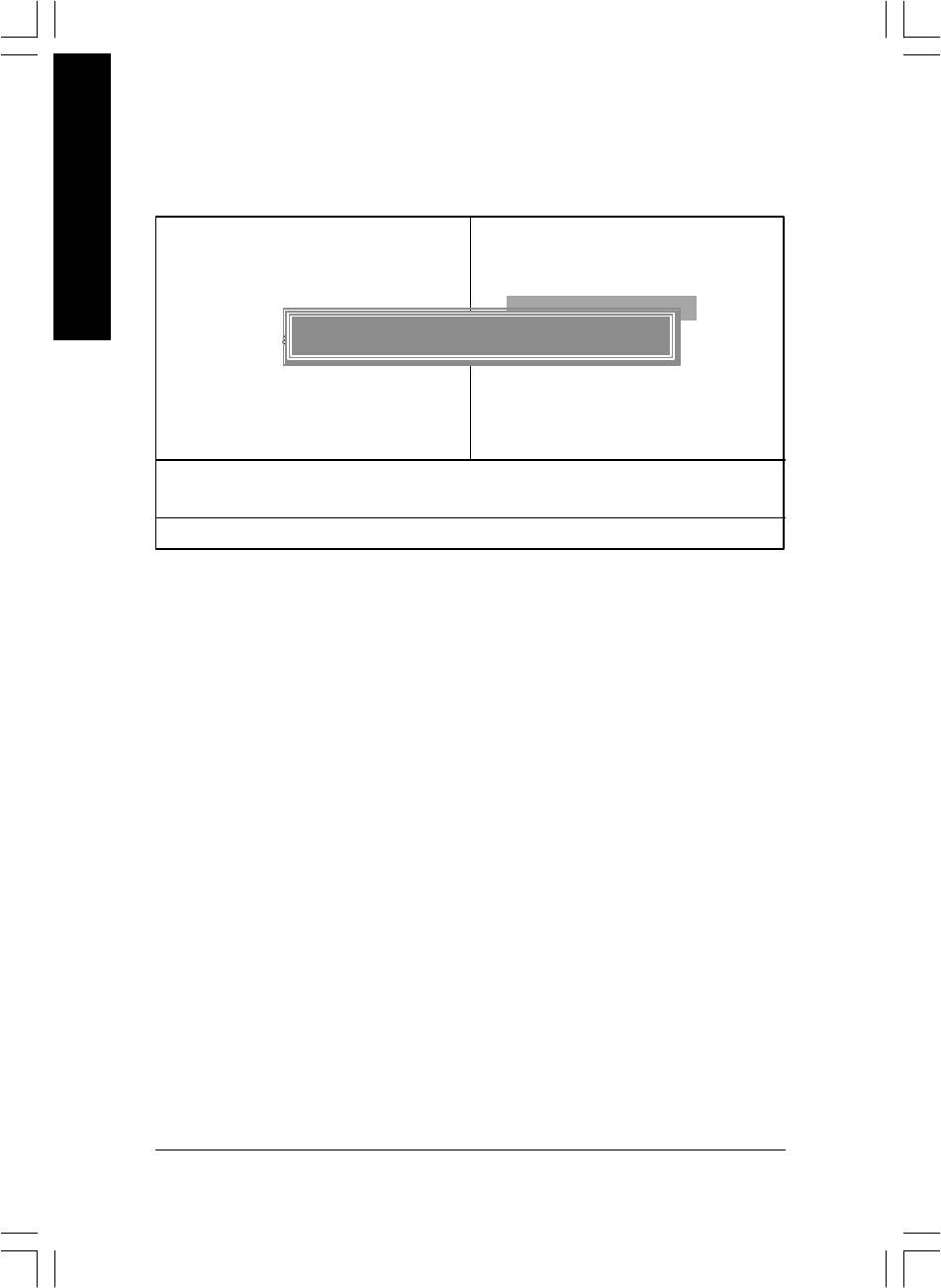
Load Fail-Safe Defaults
CMOS Setup Util ity-Copyright (C) 1984-2003 Award Software
English
} Standard CMOS Features
Load Fail-Safe De faults
} Advanced BIOS Fe atures
Load Optimized De faults
} Integrated Peripherals
Set Supervisor Password
} Power Management Setup
Load Fail-Safe Defaults (Y/N) ? Y
Set User Password
} PnP/PCI Configurations
Save & Exit Setup
} PC Health Status
Exit Without Saving
} Frequency/Vol tage Control
ESC: Quit higf: Select Item
F8: Q-Flash F10: Save & Exit Setup
Load Fail-Safe De faults
Figure 11: Load Fail-Safe Defaults
Load Fail-Safe Defaults
Fail-Safe defaults contain the most appropriate values of the system parameters that allow
minimum system performance.
- 54 -GA-8IP900MK Motherboard
8ip900mk_1001_b.p65 2003/4/22, 下午 03:5554
English
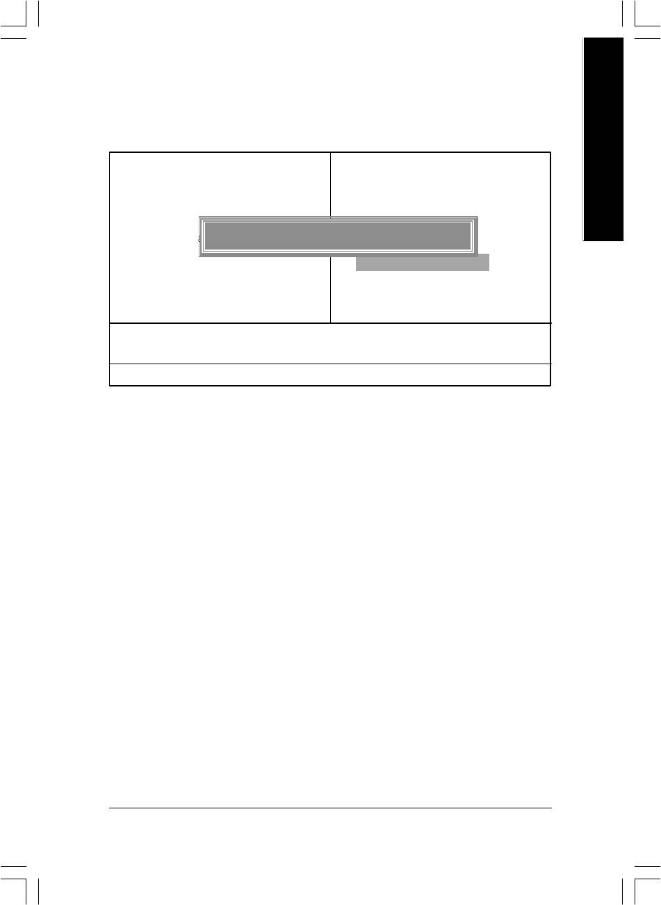
Load Optimized Defaults
CMOS Setup Util ity-Copyright (C) 1984-2003 Award Software
} Standard CMOS Features
Load Fail-Safe De faults
} Advanced BIOS Fe atures
Load Optimized De faults
} Integrated Peripherals
Set Supervisor Password
} Power Management Setup
Load Optimized Defaults (Y/N) ? Y
Set User Password
} PnP/PCI Configurations
Save & Exit Setup
} PC Health Status
Exit Without Saving
} Frequency/Vol tage Control
ESC: Quit higf: Select Item
F8: Q-Flash F10: Save & Exit Setup
Load Optimized De faults
Figure 12: Load Optimized Defaults
Load Optimized Defaults
Selecting this field loads the factory defaults for BIOS and Chipset Features which the
system automatically detects.
- 55 - BIOS Setup
8ip900mk_1001_b.p65 2003/4/22, 下午 03:5555
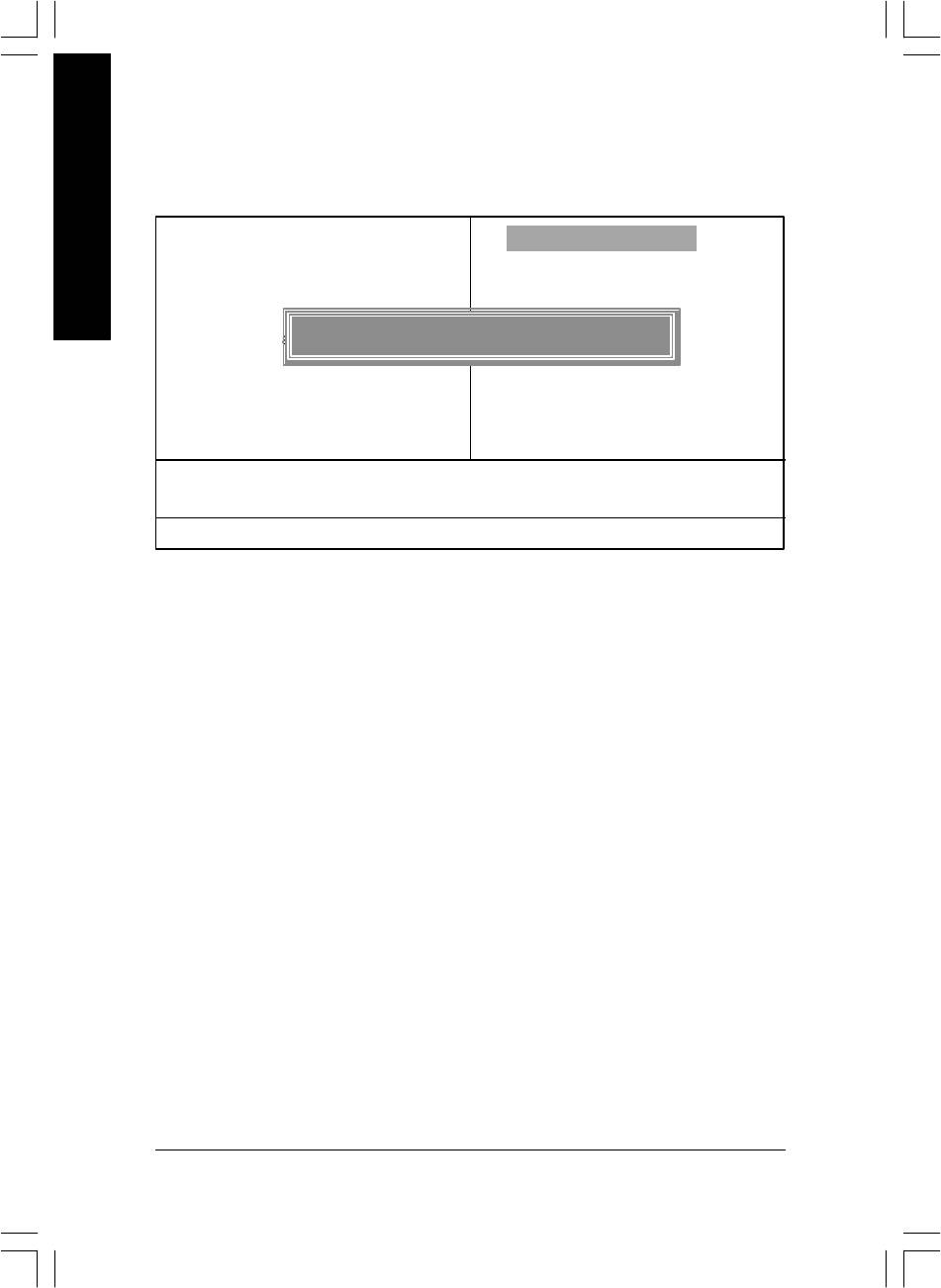
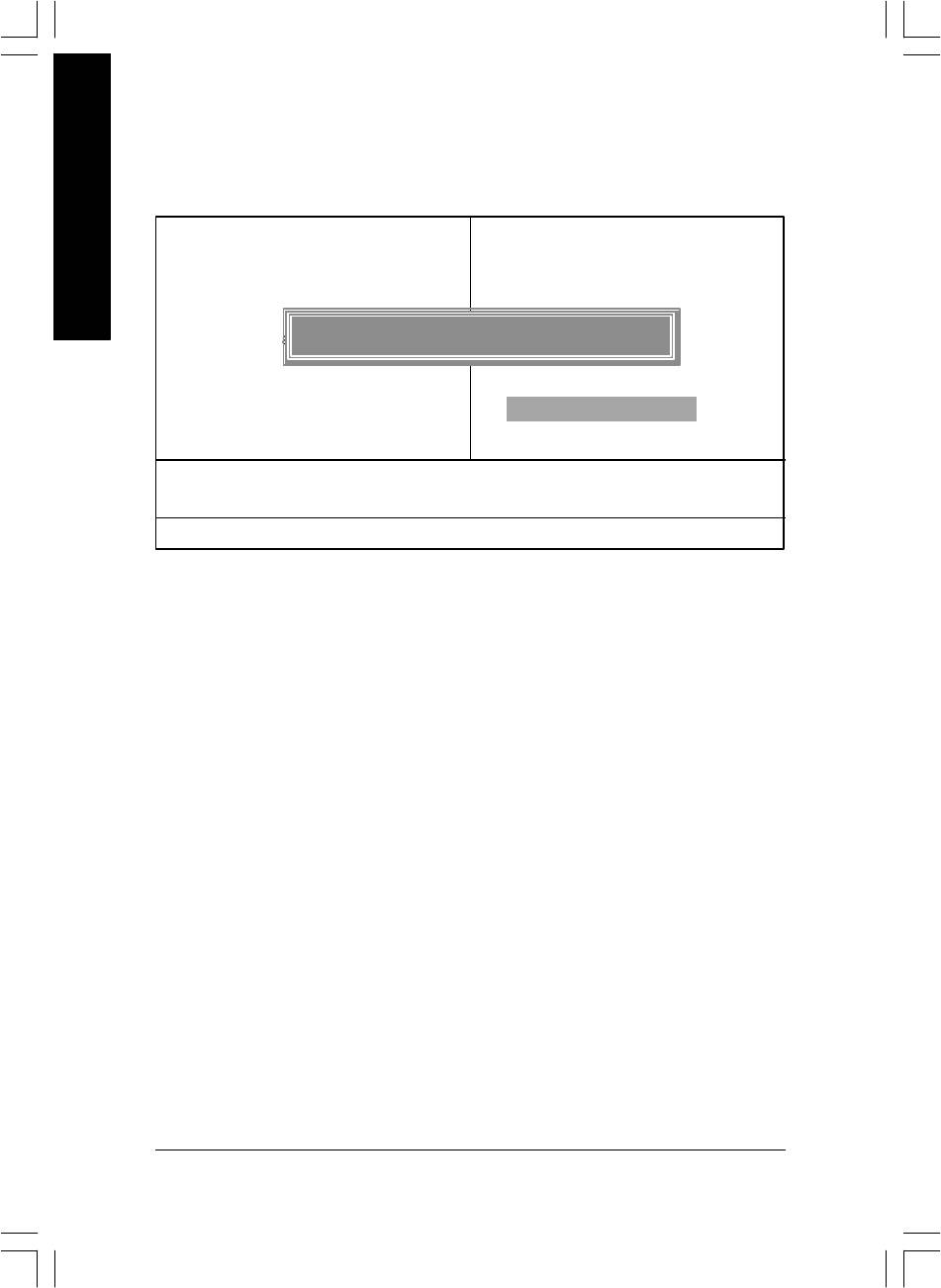
Set Supervisor/User Password
CMOS Setup Util ity-Copyright (C) 1984-2003 Award Software
English
} Standard CMOS Features
Load Fail-Safe De faults
} Advanced BIOS Fe atures
Load Optimized De faults
} Integrated Peripherals
Set Supervisor Password
} Power Management Setup
Enter Password :
Set User Password
} PnP/PCI Configurations
Save & Exit Setup
} PC Health Status
Exit Without Saving
} Frequency/Vol tage Control
ESC: Quit higf: Select Item
F8: Q-Flash F10: Save & Exit Setup
Change/Set/Dis able Password
Figure 13: Password Setting
When you select this function, the following message will appear at the center of the screen to assist
you in creating a password.
Type the password, up to eight characters, and press <Enter>. You will be asked to confirm the
password. Type the password again and press <Enter>. You may also press <Esc> to abort the
selection and not enter a password.
To disable password, just press <Enter> when you are prompted to enter password. A message
"PASSWORD DISABLED" will appear to confirm the password being disabled. Once the password is
disabled, the system will boot and you can enter Setup freely.
The BIOS Setup program allows you to specify two separate passwords:
SUPERVISOR PASSWORD and a USER PASSWORD. When disabled, anyone may access
all BIOS Setup program function. When enabled, the Supervisor password is required for entering the
BIOS Setup program and having full configuration fields, the User password is required to access only
basic items.
If y ou select "System" at "Passw ord C heck" in Advance BIOS Features Menu, you will be
prompted for the password every time the system is rebooted or any time you try to enter Setup Menu.
If you select "Setup" at "Password Check" in Advance BIOS Features Menu, you will be prompted
only when you try to enter Setup.
- 56 -GA-8IP900MK Motherboard
8ip900mk_1001_b.p65 2003/4/22, 下午 03:5556
English
Save & Exit Setup
CMOS Setup Util ity-Copyright (C) 1984-2003 Award Software
} Standard CMOS Features
Load Fail-Safe De faults
} Advanced BIOS Fe atures
Load Optimized De faults
} Integrated Peripherals
Set Supervisor Password
} Power Management Setup
Save to CMOS and EXIT (Y/N) ? Y
Set User Password
} PnP/PCI Configurations
Save & Exit Setup
} PC Health Status
Exit Without Saving
} Frequency/Vol tage Control
ESC: Quit higf: Select Item
F8: Q-Flash F10: Save & Exit Setup
Save Data to CMOS
Figure 14: Save & Exit Setup
Type "Y" will quit the Setup Utility and save the user setup value to RTC CMOS.
Type "N" will return to Setup Utility.
- 57 - BIOS Setup
8ip900mk_1001_b.p65 2003/4/22, 下午 03:5557
Exit Without Saving
CMOS Setup Util ity-Copyright (C) 1984-2003 Award Software
English
} Standard CMOS Features
Load Fail-Safe De faults
} Advanced BIOS Fe atures
Load Optimized De faults
} Integrated Peripherals
Set Supervisor Password
} Power Management Setup
Quit Without Saving (Y/N) ? N
Set User Password
} PnP/PCI Configurations
Save & Exit Setup
} PC Health Status
Exit Without Saving
} Frequency/Vol tage Control
ESC: Quit higf: Select Item
F8: Q-Flash F10: Save & Exit Setup
Abandon all Data
Figure 15: Exit Without Sav ing
Type "Y" will quit the Setup Utility without saving to RTC CMOS.
Type "N" will return to Setup Utility.
- 58 -GA-8IP900MK Motherboard
8ip900mk_1001_b.p65 2003/4/22, 下午 03:5558

English
- 59 - BIOS Setup
8ip900mk_1001_b.p65 2003/4/22, 下午 03:5559

English
- 60 -GA-8IP900MK Motherboard
8ip900mk_1001_b.p65 2003/4/22, 下午 03:5560

English
Chapter 4 Technical Reference
™
@BIOS
Introduction
™
Gigabyte announces @BIOS
Windows BIOS live update utility
Have you ever updated BIOS by yourself? Or like
many other people, you just know what BIOS is,
but always hesitate to update it? Because you think
updating newest BIOS is unnecessary and actually
you don't know how to update it.
Maybe not like others, you are very experienced in BIOS updating and spend quite a lot of time
to do it. But of course you don’t like to do it too much. First, download different BIOS from website and
then switch the operating system to DOS mode. Secondly, use different flash utility to update BIOS.
The above process is not a interesting job. Besides, always be carefully to store the BIOS source code
correctly in your disks as if you update the wrong BIOS, it will be a nightmare.
Certainly, you wonder why motherboard vendors could not just do something right to save your
time and effort and save you from the lousy BIOS updating work? Here it comes! Now Gigabyte
announces @BIOS— the first Windows BIOS live update utility. This is a smart BIOS update software.
It could help you to download the BIOS from internetand update it. Not like the other BIOS update
software, it's a Windows utility. With the help of "@BIOS", BIOS updating is no more than a click.
Besides, no matter which mainboard you are using, if it’s a Gigabyte's product*, @BIOS help you
to maintain the BIOS. This utility could detect your correct mainboard model and help you to choose the
BIOS accordingly. It then downloads the BIOS from the nearest Gigabyte ftp site automatically. There
are several different choices; you could use "Internet Update" to download and update your BIOS
directly. Or you may want to keep a backup for your current BIOS, just choose "Save Current BIOS"
to save it first. You make a wise choice to use Gigabyte, and @BIOS update your BIOS smartly. You
are now worry free from updating wrong BIOS, and capable to maintain and manage your BIOS
easily. Again, Gigabyte's innovative product erects a milestone in mainboard industries.
For such a wonderful software, how much it costs? Impossible! It's free! Now, if you buy a
Gigabyte's motherboard, you could find this amazing software in the attached driver CD. But please
remember, connected to internet at first, then you could have a internet BIOS update from your
Gigabyte @BIOS.
- 61 -
Technical Reference
8ip900mk_1001_t.p65 2003/4/22, 下午 03:5561

™
EasyTune
4 Introduction
™
Gigabyte announces EasyTune
4
Windows based Overclocking utility
English
EasyTune 4 carries on the heritage so as to pave the way for future generations.
Overclock might be one of the most common issues
in computer field. But have many users ever tried it?
The answer is probably "no". Because "Overclock"
is thought to be very difficult and includes a lot of
technical know-how, sometimes "Overclock" is
even considered as special skills found only in some
enthusiasts. But as to the experts in "Overclock",
what's the truth? They may spend quite a lot of time
and money to study, try and use many different
hardware or BIOS tools to do "Overclock". And even with these technologies, they still learn that it's
quite a risk because the safety and stability of an "Overclock" system is unknown. Now everything
is different because of a Windows based overclocking utility "EasyTune 4" --announced by Gigabyte.
This windows based utility has totally changed the gaming rule of "Overclock". This is the first
windows based overclocking utility is suitable for both normal and power users. Users can choose
either "Easy Mode" or "Advanced Mode" for overclocking at their convenience. For users who
choose "Easy Mode", they just need to click "Auto Optimize" to have autoed and immediate CPU
overclocking. This software will then overdrive CPU speed automatically with the result being shown
in the control panel. If users prefer "Overclock" by them, there is also another choice. Click "Advanced
Mode" to enjoy "sport drive" class Overclocking user interface. "Advanced Mode", allows users to
change the system bus / AGP / Memory working frequency in small increments to get ultimate system
performance. It operates in coordination with Gigabyte motherboards. Besides, it is different from other
traditional over-clocking methods, EasyTune 4 doesn't require users to change neither BIOS nor
hardware switch/ jumper setting; on the other hand, they can do "Overclock" at easy step . Therefore,
this is a safer way for "Overclock" as nothing is changed on software or hardware. If user runs
EasyTune 4 over system's limitation, the biggest lost is only to restart the computer again and the side
effect is then well controlled. Moreover, if one well-performed system speed has been tested in
EasyTune 4, user can "Save" this setting and "Load" it in next time. Obviously, Gigabyte EasyTune
4 has already turned the "Overclock" technology toward to a newer generation. This wonderful
software is now free bundled in Gigabyte motherboard attached in driver CD. Users may make a test
drive of "EasyTune 4" to find out more amazing features by themselves.
*Some Gigabyte products are not fully supported by EasyTune 4. Please find the products supported
list in the web site.
*Any "Overclocking action" is at user's risk, Gigabyte Technology will not be responsible for any
damage or instability to your processor, motherboard, or any other components.
GA-8IP900MK Motherboard
- 62 -
8ip900mk_1001_t.p65 2003/4/22, 下午 03:5562
English
Flash BIOS Method Introduction
Method 1 : Q-Flash
A. What is Q-Flash Utility?
Q-Flash utility is a pre-O.S. BIOS flash utility enables users to update its BIOS within BIOS
mode, no more fooling around any OS.
B. How to use Q-Flash?
a. After power on the computer, pressing <Del> immediately during POST (Power On Self Test) it
will allow you to enter AWARD BIOS CMOS SETUP, then press <F8> to enter Q-Flash utility.
CMOS Setup Utility-Copyright (C) 1984-2003 Award Software
} Standard CMOS Features
Load Fail-Safe Defaults
} Advanced BIOS Features
Load Optimized Defaults
} Integrated Peripherals
Set Supervisor Password
} Power Management Setup
Set User Password
Enter Q-Flash Utility (Y/N)? Y
} PnP/PCI Configurations
Save & Exit Setup
} PC Health Status
Exit Without Saving
} Frequency/Voltage Control
ESC: Quit higf: Select Item
F8: Q-Flash F10: Save & Exit Setup
Tim e, Date, Hard Disk Type...
b. Q-Flash Utility
Q-Flash Utility v1.30
Flash Type/Size ......................................................... SST 49LF002A 256K
Keep DMI Data Enable
Update BIOS from Floppy
Save BIOS to Floppy
Enter : Run h/i : Move ESC : Reset F10 : Power Off
- 63 -
Technical Reference
8ip900mk_1001_t.p65 2003/4/22, 下午 03:5563

Load BIOS From Floppy
!In the A:drive, insert the "BIOS" diskette, then Press Enter to Run.
1 File(s)
English
xxxx .xxx 256K
Total size: 1.39M Free size: 1.14M
F5: Refresh DEL: Delete
Where xxxx.xxx is name of the BIOS file.
! Press Enter to Run.
Are you sure to update BIOS?
[Enter] to contiune or [ESC] to abort ...
! Press Enter to Run.
!! Copy BIOS Completed - Pass !!
Please press any key to continue ...
Congratulation! You have completed the flashed and now can restart system.
GA-8IP900MK Motherboard
- 64 -
8ip900mk_1001_t.p65 2003/4/22, 下午 03:5564
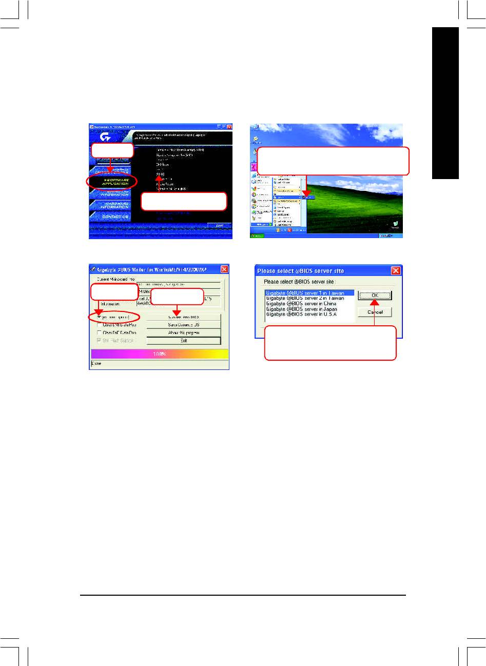
English
Method 2 : @BIOS Utility
™
If you don't have DOS boot disk, we recommend that you used Gigabyte @BIOS
program to flash
BIOS.
Press here.
2. Click Start/ All Programs/ GIGABYTE/
@BIOS.
1. Click "@BIOS" item.
(1)
(2)
3.Click "P".
Click here
4. Please select @BIOS sever site,
then Click "OK".
(3)
(4)
Methods and steps:
I. Update BIOS through Internet
a. Click "Internet Update" icon
b. Click "Update New BIOS" icon
™
c. Select @BIOS
sever
d. Select the exact model name on your motherboard.
e. System will automatically download and update the BIOS.
- 65 -
Technical Reference
8ip900mk_1001_t.p65 2003/4/22, 下午 03:5565

II. Update BIOS NOT through Internet:
a. Do not click "Internet Update" icon
b. Click "Update New BIOS"
c. Please select "All Files" in dialog box while opening the old file.
English
d. Please search for BIOS unzip file, downloading from internet or any other methods (such as:
8IP900MK.F2).
e. Complete update process following the instruction.
III. Save BIOS
In the very beginning, there is "Save Current BIOS" icon shown in dialog box. It means to save the
current BIOS version.
IV. Check out supported motherboard and Flash ROM:
In the very beginning, there is "About this program" icon shown in dialog box. It can help you check
out which kind of motherboard and which brand of Flash ROM are supported.
Note:
a. In method I, if it shows two or more motherboard's model names to be selected, please make
sure your motherboard's model name again. Selecting wrong model name will cause the
system unbooted.
b. In method II, be sure that motherboard's model name in BIOS unzip file are the same as your
motherboard's. Otherwise, your system won't boot.
™
c. In method I, if the BIOS file you need cannot be found in @BIOS
server, please go onto
Gigabyte's web site for downloading and updating it according to method II.
d. Please note that any interruption during updating will cause system unbooted
GA-8IP900MK Motherboard
- 66 -
8ip900mk_1001_t.p65 2003/4/22, 下午 03:5666
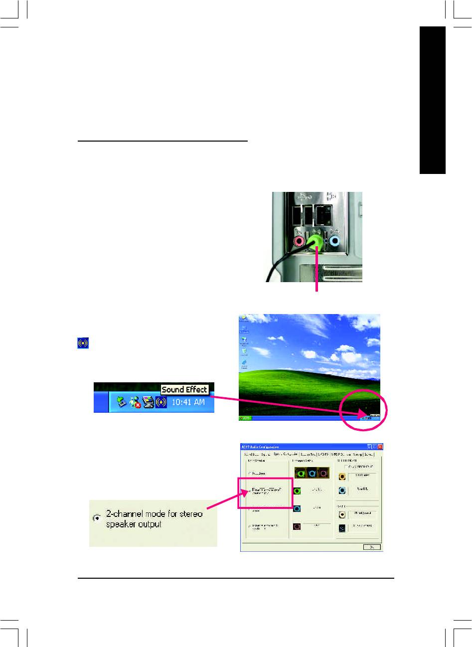
English
2- / 4- / 6-Channel Audio Function Introuction
The installation of Windows 98SE/2K/ME/XP is very simple. Please follow next step to install the
function!
Stereo Speakers Connection and Settings:
We recomm end that you use the speaker with amplifier to acqiire the best sound effect if the stereo
output is applied.
STEP 1:
Connect the stereo speakers or earphone to "Line
Out".
Line Out
STEP 2 :
After installation of the audio driver, you'll find an
icon on the taskbar's status area. Click the
audio icon "Sound Effect" from the windows tray at
the bottom of the screen.
STEP 3:
Select "Speaker Configuration", and choose the
"2 channels for stereo speakers out put".
- 67 -
Technical Reference
8ip900mk_1001_t.p65 2003/4/22, 下午 03:5667
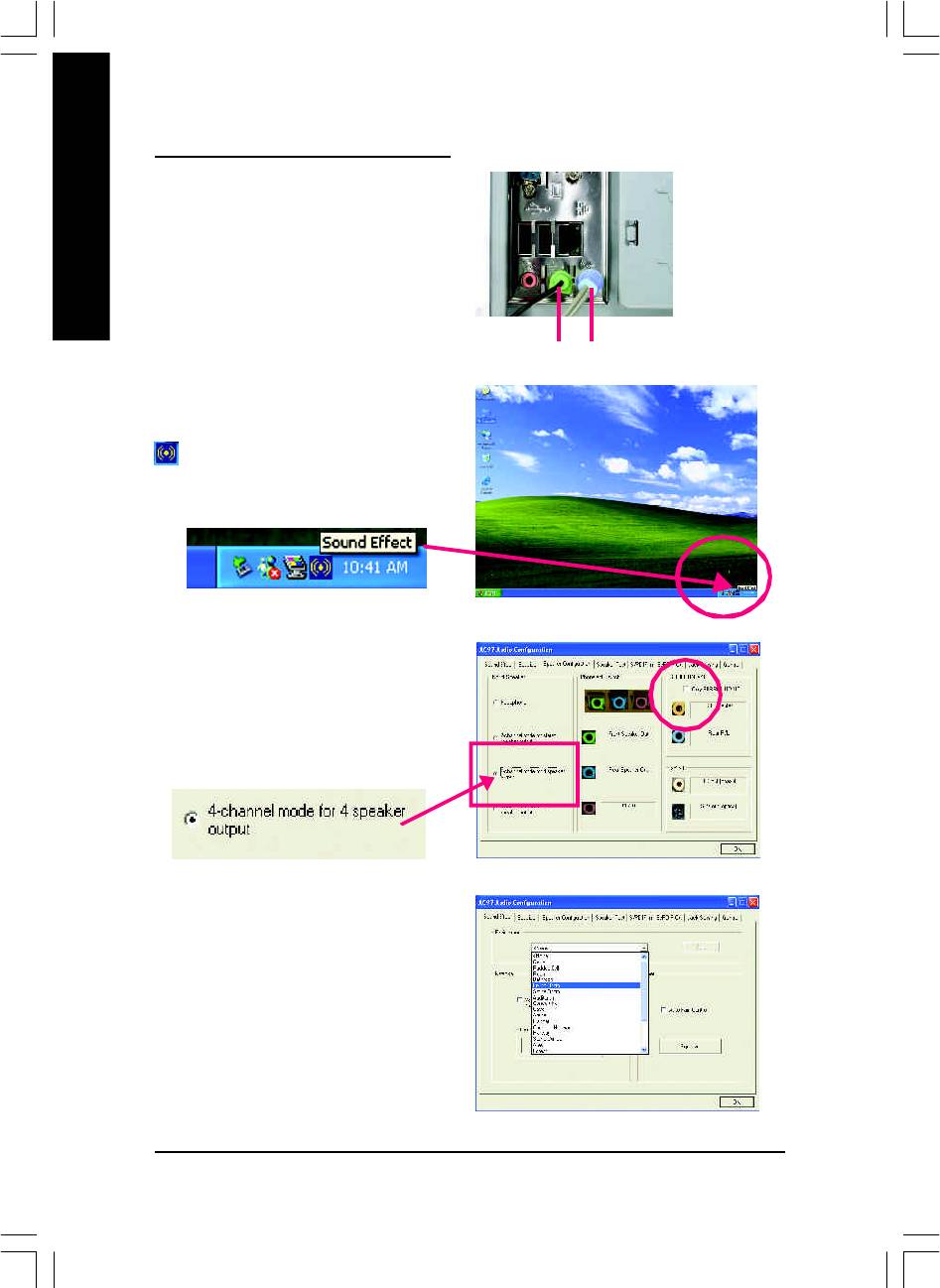
4 Channel Analog Audio Output Mode
STEP 1 :
Connect the front channels to "Line Out", the rear
channels to "Line In".
English
Line Out Line In
STEP 2 :
After installation of the audio driver, you'll find an
icon on the taskbar's status area. Click the
audio icon "Sound Effect" from the windows tray at
the bottom of the screen.
STEP 3 :
Select "Speaker Configuration", and choose the "4
channels for 4 speakers out put".
Disable "Only SURROUND-KIT",
and press "OK".
When the "Environm ent settings" is "None", the
sound would be performed as stereo mode (2 chan-
nels output). Please select the other settings for 4
channels output.
GA-8IP900MK Motherboard
- 68 -
8ip900mk_1001_t.p65 2003/4/22, 下午 03:5668
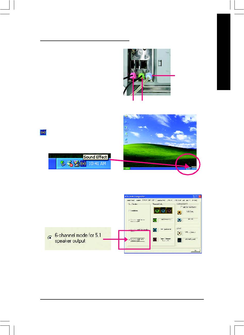
English
Basic 6 Channel Analog Audio Output Mode
Use the back audio panel to connect the audio
output without any additional module.
STEP 1 :
Connect the front channels to "Line Out", the rear
Line In
channels to "Line In", and the Center/Subwoofer
channels to "MIC In".
M IC In
Line Out
STEP 2 :
After installation of the audio driver, you'll find an
icon on the taskbar's status area. Click the
audio icon "Sound Effect" from the windows tray at
the bottom of the screen.
STEP 3 :
Select "Speaker Configuration", and choose the
"6 channels for 5.1 speakers out put".
Disable "Only SURROUND-KIT" and pess "OK".
- 69 -
Technical Reference
8ip900mk_1001_t.p65 2003/4/22, 下午 03:5669
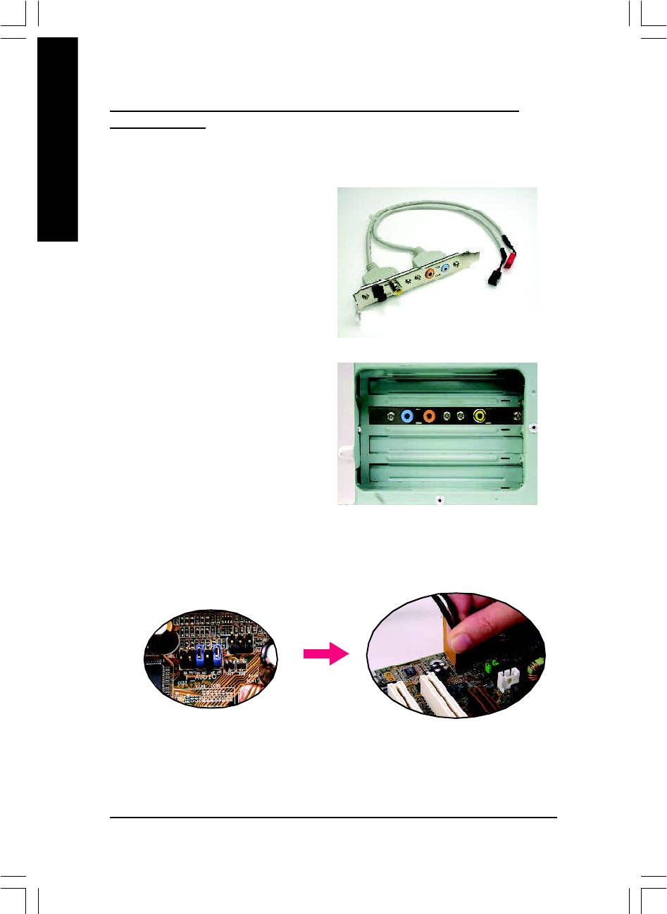
Advanced 6 Channel Analog Audio Output Mode (using Audio Combo Kit,
Optional Device):
(Audio Combo Kit provides SPDIF output port : optical & coaxis and SURROUND-KIT : Rear R/L &
Center/subwoofer)
English
SURROUND-KIT access analog output to rear
channels and Center/Subwoofer channels. It is the
best solution if you need 6 channel output, Line In
and MIC at the sam e tim e. "SURROUND-KIT" is
included in the GIGABYTE unique "Audio Com bo
Kit" as picture.
STEP 1 :
Insert the "Audio Com bo Kit" in the back of the
case,and fix it with the screw.
STEP 2 :
Connect the "SURROUND-KIT" to SUR_CEN on
the M/B.
GA-8IP900MK Motherboard
- 70 -
8ip900mk_1001_t.p65 2003/4/22, 下午 03:5670
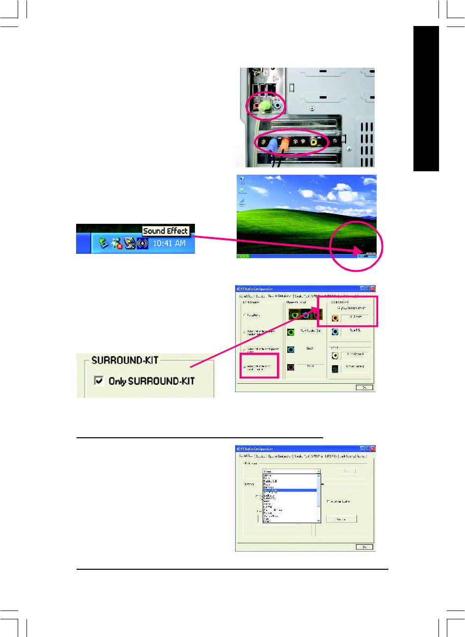
English
STEP 3 :
Connect the front channels to back audio panel's
"Line Out", the rear channels to SURROUND-KIT's
REAR R/L, and the Center/Subwoofer channels to
SURROUND-KIT's SUB CENTER.
STEP 4 :
Click the audio icon "Sound Effect" from the win-
dows tray at the bottom of the screen.
STEP 5 :
Select "Speaker Configuration", and choose the
"6 channels for 5.1 speakers out put".
Enable "Only SURROUND-KIT" and press "OK".
Basic & Advanced 6 Channel Analog Audio Output Mode Notes:
When the "Environm ent settings" is "None", the
sound would be performed as stereo mode (2 chan-
nels output). Please select the other settings for 6
channels output.
- 71 -
Technical Reference
8ip900mk_1001_t.p65 2003/4/22, 下午 03:5671
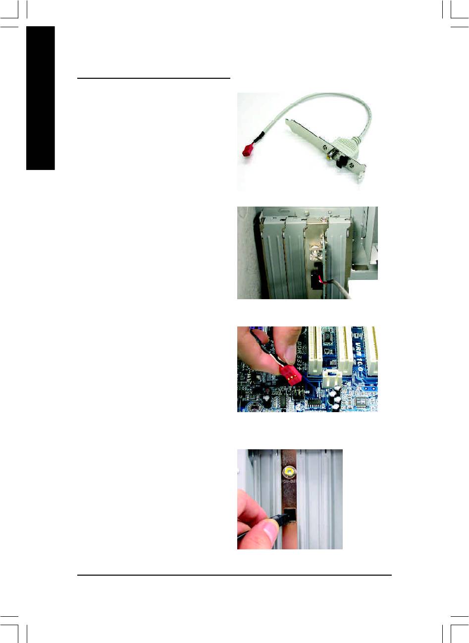
SPDIF Output Device (Optional Device)
A "S/PDIF output" devi ce is available on the
motherboard. Cable with rear bracket is provided
English
and could link to the "S/PDIF output" connector (As
picture.) For the further linkage to decoder, rear
bracket provides coaxial cable and Fiber connect-
ing port.
1. Connect the SPDIF output device to the rear
bracket of PC, and fix it with screw.
2. Connect SPDIF wire to the m otherboard.
3. Connect co-axial or optical output to the AC3
decoder.
GA-8IP900MK Motherboard
- 72 -
8ip900mk_1001_t.p65 2003/4/22, 下午 03:5672
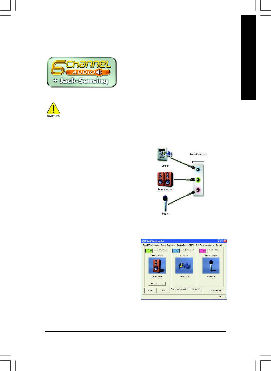
English
Jack-Sensing Introuction
Jack-Sensing provides audio connectors error-detection
function.
Install Microsoft DirectX8.1 before to enable Jack-Sensing support for Windows 98/98SE/2000
/M E.
Jack-Sensing includes 2 parts: AUTO and M ANUAL. Following is an example for 2 channels
(Windows XP):
Introduction of audio connectors
You may connect CDROM, Walkman or others
audio input devices to Line In jack, speakers,
earphone or others output devices to Line Out jack,
and microphone to M IC In jack.
Auto-detecting:
Please connect the devices to the right jacks as
above. A window will appear as right picture if you
setup the devices properly.
Please note that 3D audio function will only appear
when 3D audio inputs.
- 73 -
Technical Reference
8ip900mk_1001_t.p65 2003/4/22, 下午 03:5673
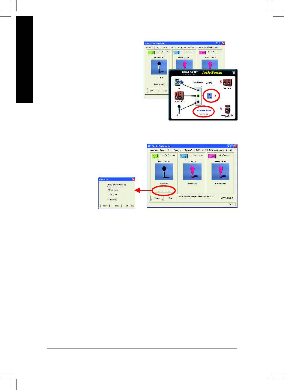
If you set wrong with the connectors, the warning
message will come out as right picture.
English
Manual setting:
If the device picture shows different from what you
set, please press "Manual Selection" to set.
GA-8IP900MK Motherboard
- 74 -
8ip900mk_1001_t.p65 2003/4/22, 下午 03:5674

English
- 75 -
Technical Reference
8ip900mk_1001_t.p65 2003/4/22, 下午 03:5675

English
GA-8IP900MK Motherboard
- 76 -
8ip900mk_1001_t.p65 2003/4/22, 下午 03:5676
Оглавление
- DECLARATION OF CONFORMITY
- Chapter 5 Appendix
- FAQ
- Troubleshooting
- Technical Support/RMA Sheet
- Acronyms


