Gigabyte 8I845GE-RZC: Step 3: Install AGP Card
Step 3: Install AGP Card: Gigabyte 8I845GE-RZC
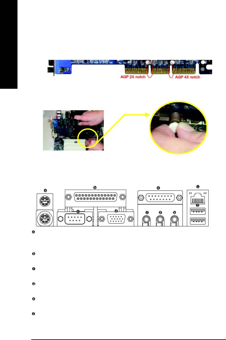
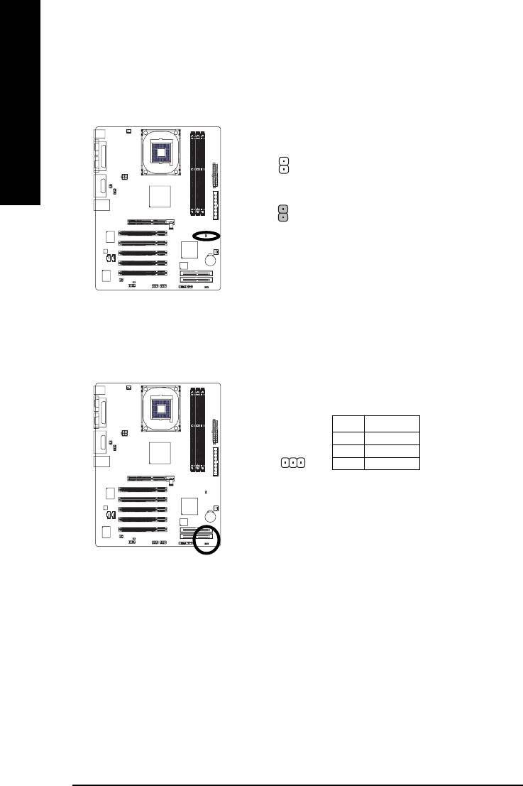
Step 3: Install AGP Card
1. Read the related expansion card's instruction document before installing the expansion card into
the computer.
2. Please make sure your AGP card is AGP 4X (1.5V).
English
3. Please carefully pull out the small white- drawable bar at the end of the AGP slot when you try to
install/ Uninstall the AGP card. Please align the AGP card to the onboard AGP slot and press firmly
down on the slot .Make sure your AGP card is locked by the small white- drawable bar.
AGP Card
Step 4: Install I/O Peripherals Cables
Step 4-1: I/O Back Panel Introduction
*
PS/2 Keyboard and PS/2 Mouse Connector
To install a PS/2 port keyboard and mouse, plug the mouse to the upper port (green) and the keyboard
to the lower port (purple).
Parallel Port
The parallel port allows connection of a printer, scanner and other peripheral devices.
Serial Port
Devices like mouses, modems, and etc. can be connected to Serial port.
VGA Port
Monitor can be connected to VGA port.
Game/MIDI port
This connector supports joystick, MIDI keyboard and other related audio devices.
Line Out (Front Speaker Out)
Connect the stereo speakers, earphone or front surround channels to this connector.
"*" For 8I845GE-RZ only.
8I845GE-RZ Series Motherboard
- 12 -
English
Line In
Devices like CD-ROM, walkman etc. can be connected to Line In jack.
MIC In
Microphone can be connected to MIC In jack.
LAN Port *
The LAN port provides Internet connection.
USB port
Before you connect your device(s) into USB connector(s), please make sure your device(s) such
as USB keyboard, mouse, scanner, zip, speaker...etc. have a standard USB interface. Also make
sure your OS supports USB controller. If your OS does not supportUSB controller, please con-
tact OS vendor for possible patch or driver upgrade. For more information please contact your
OS or device(s) vendors.
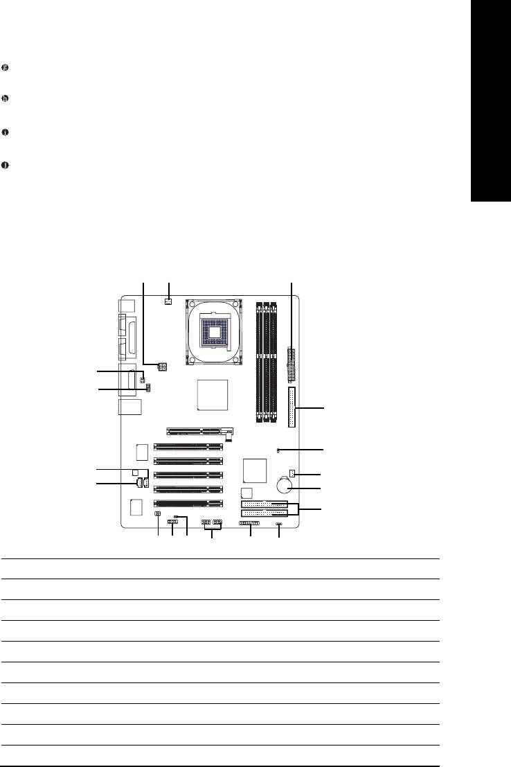
Step 4-2: Connectors Introduction
1
32
13
10
5
17
7
4
11
9
6
14
81612
1815
1) ATX_12V
10) F_AUDIO
2) ATX
11) CD_IN
3) CPU_FAN
12) SPDIF_IO
4) SYS_FAN
13) SUR_CEN
5) FDD
14) F_USB1 / F_USB2
6) IDE1 / IDE2
15) CI
7) AUX_IN
16) COMB
8) F_PANEL
17) CLR_CMOS
9) BAT
18) PWR_LED
"*" For 8I845GE-RZ only.
- 13 - Hardware Installation Process
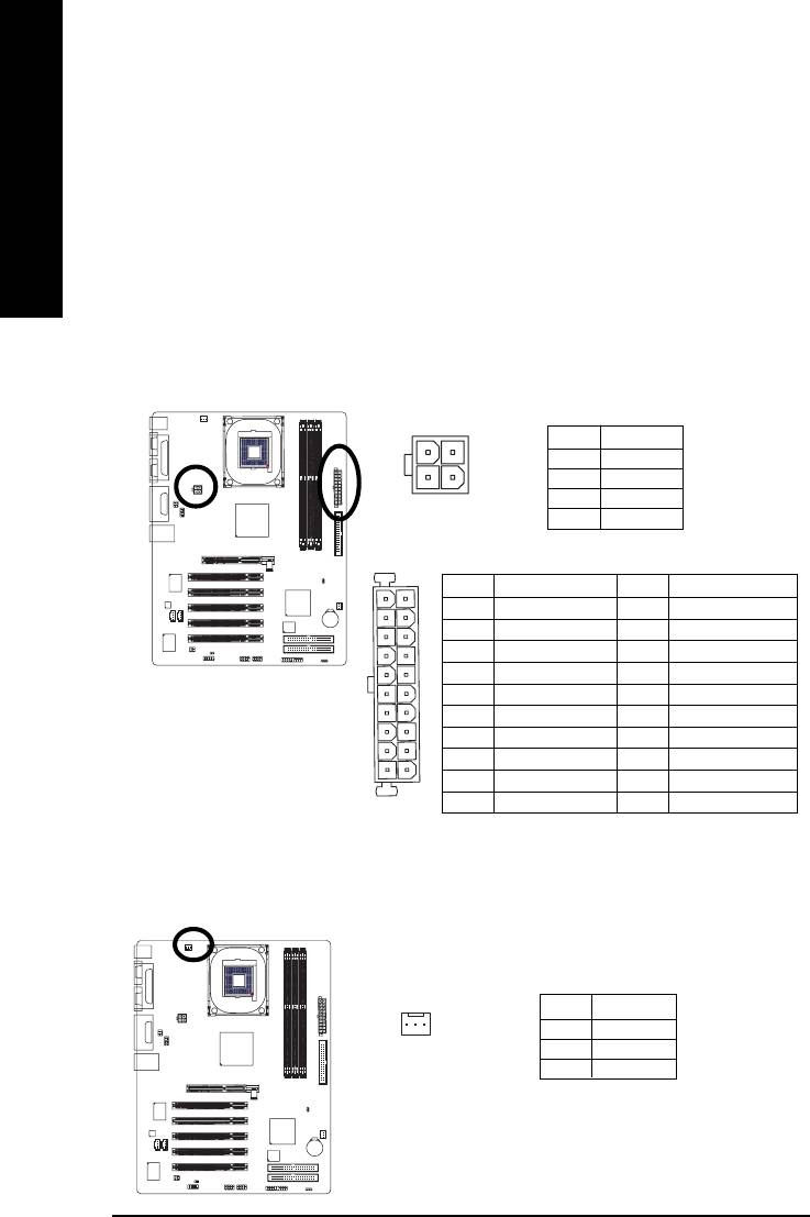
1/2) ATX_12V/ATX (Power Connector)
With the use of the power connector, the power supply can supply enough stable power to all
the components on the motherboard. Before connecting the power connector, please make sure
that all components and devices are properly installed. Align the power connector with its
English
proper location on the motherboard and connect tightly.
The ATX_12V power connector mainly supplies power to the CPU. If the ATX_12V power
connector is not connected, the system will not start.
Caution!
Please use a power supply that is able to handle the system voltage requirements. It is
recommended that a power supply that can withstand high power consumption be used (300W
or greater). If a power supply is used that does not provide the required power, the result can
lead to an unstable system or a system that is unable to start.
Pin No. Definition
4
2
1 GND
3
1
2 GND
3 +12V
4 +12V
Pin No. Definition
Pin No. Definition
11
1
1 3.3V
11 3.3V
2 3.3V
12 -12V
3 GND
13 GND
4 VCC
14 PS_ON(soft on/off)
5 GND
15 GND
6 VCC
16 GND
7 GND
17 GND
8 Power Good
18 -5V
20
10
9 5V SB (stand by +5V)
19 VCC
10 +12V
20 VCC
3) CPU_FAN (CPU FAN Connector)
Please note, a proper installation of the CPU cooler is essential to prevent the CPU from running
under abnormal condition or damaged by overheating.The CPU fan connector supports Max.
current up to 600 mA.
Pin No. Definition
1
1 GND
2 +12V
3 Sense
8I845GE-RZ Series Motherboard
- 14 -
English
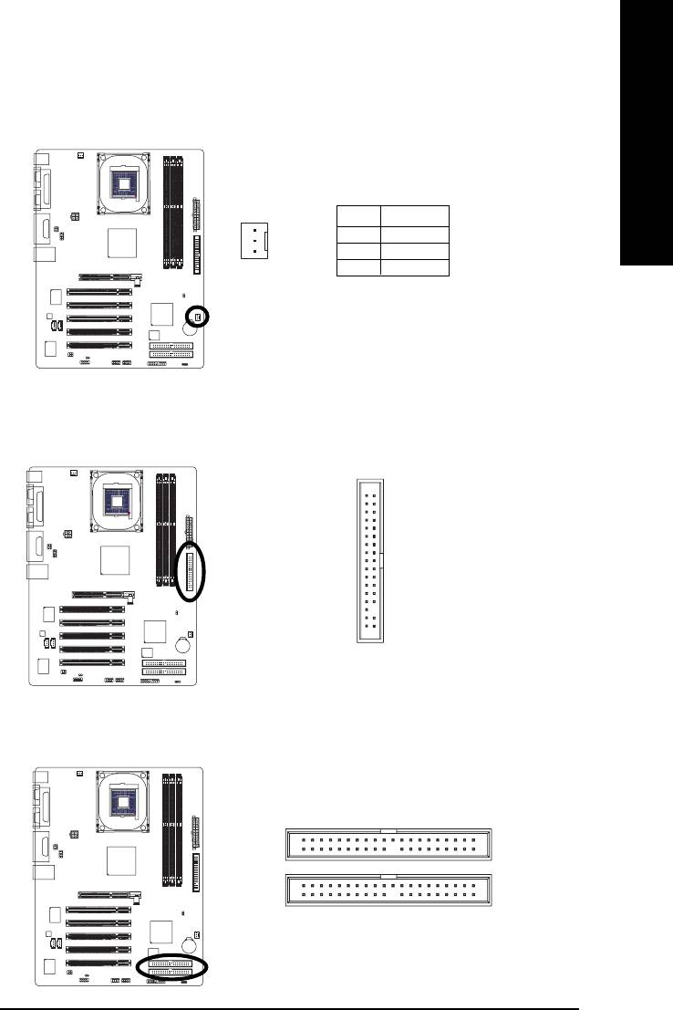
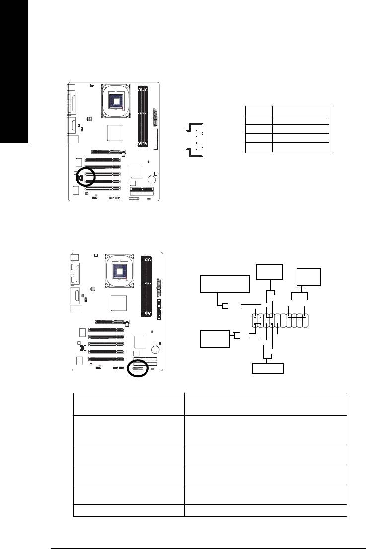
4) SYS_FAN (System FAN Connector)
This connector allows you to link with the cooling fan on the system case to lower the system
temperature.
Pin No. Definition
1 GND
1
2 +12V
3 Sense
5) FDD (Floppy Connector)
Please connect the floppy drive ribbon cables to FDD. It supports 360K,720K,1.2M,1.44M and
2.88Mbytes floppy disk types.
The red stripe of the ribbon cable must be the same side with the Pin1.
34
33
2
1
6) IDE1/ IDE2 (IDE1/IDE2 Connector)
Please connect first harddisk to IDE1 and connect CDROM to IDE2.
The red stripe of the ribbon cable must be the same side with the Pin1.
39
1
IDE2
IDE1
40
2
- 15 - Hardware Installation Process
7) AUX_IN (AUX In Connector)
Connect other device (such as PCI TV Tunner audio out) to the connector.
English
Pin No. Definition
1
1 AUX-L
2 GND
3 GND
4 AUX-R
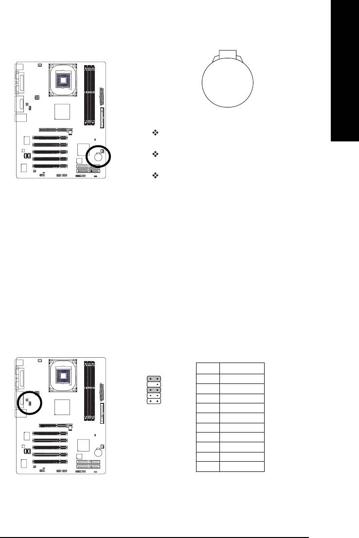
8) F_PANEL (2x10 pins connector)
Please connect the power LED, PC peaker, reset switch and power switch etc. of your chassis front
panel to the F_PANEL connector according to the pin assignment above.
Soft Power
Connector
Speaker
Message LED/Power/
Connector
Sleep LED
PW-
MSG-
SPK+
SPK-
PW+
MSG+
2
20
1
19
HD+
IDE Hard Disk
HD-
NC
Active LED
RST-
RST+
Reset Switch
HD (IDE Hard Disk Active LED) Pin 1: LED anode(+)
Pin 2: LED cathode(-)
SPK (Speaker Connector) Pin 1: VCC(+)
Pin 2- Pin 3: NC
Pin 4: Data(-)
RST (Reset Switch) Open: Normal Operation
Close: Reset Hardware System
PW (Soft Power Connector) Open: Normal Operation
Close: Power On/Off
MSG (Message LED/Power/ Pin 1: LED anode(+)
Sleep LED) Pin 2: LED cathode(-)
NC NC
8I845GE-RZ Series Motherboard
- 16 -
English
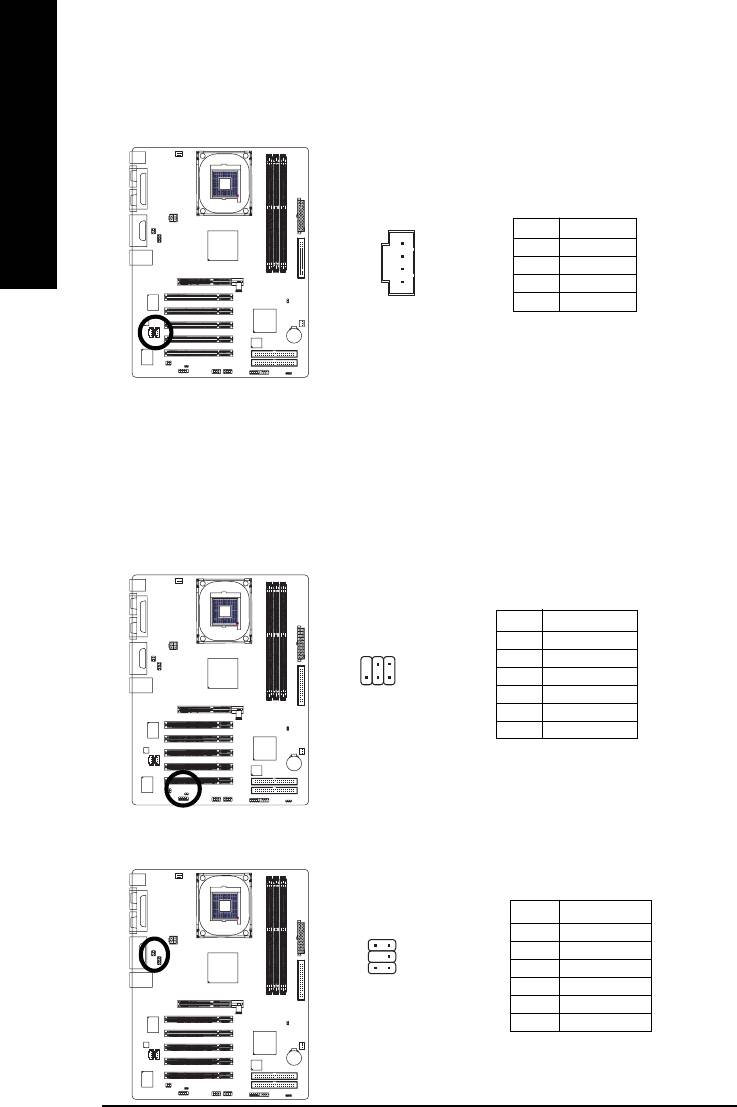
9) BAT (Battery)
+
CAUTION
Danger of explosion if battery is incorrectly
replaced.
Replace only with the same or equivalent type
recommended by the manufacturer.
Dispose of used batteries according to the
manufacturer's instructions.
If you want to erase CMOS...
1. Turn OFF the computer and unplug the power cord.
2. Remove the battery, wait for 30 second.
3. Re-install the battery.
4. Plug the power cord and turn ON the computer.
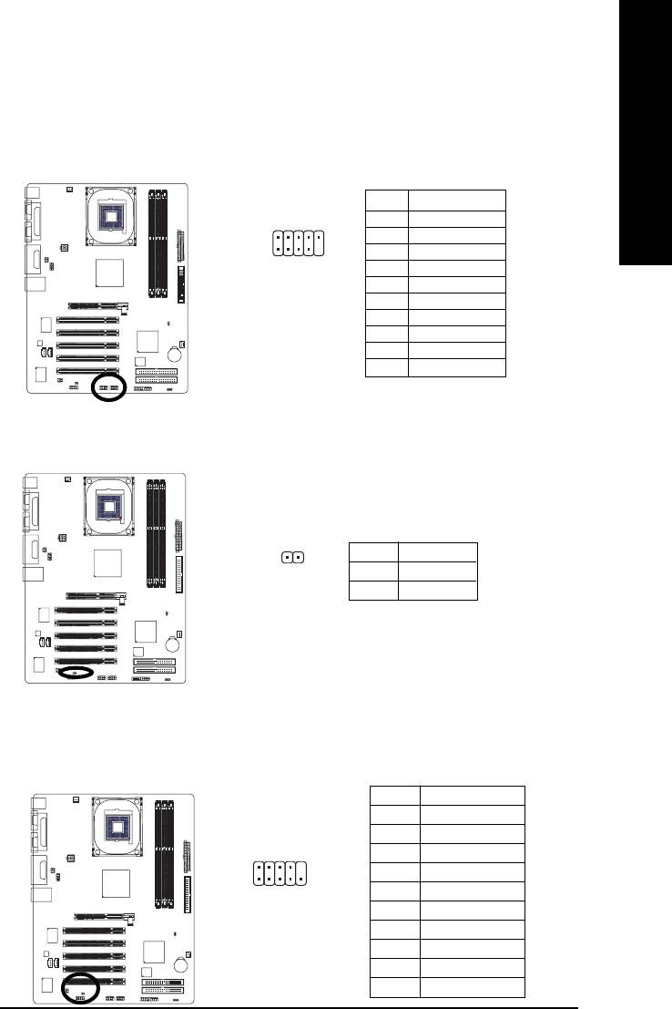
10) F_AUDIO (Front Audio Panel Connector)
If you want to use Front Audio connector, you must remove jumpers on pins 5-6, 9-10. In order to
utilize the front audio header, your chassis must have front audio connector. Also please make sure
the pin assigments on the cable are the same as the pin assigments on the MB header. To find out if
the chassis you are buying support front audio connector, please contact your dealer. Please note,
you can have the alternative of using front audio connector or of using rear audio connector to play
sound.
Pin No. Definition
10 9
1 MIC
2 GND
1
3 REF
2
4 POWER
5 FrontAudio(R)
6 RearAudio(R)
7 Reserved
8 No Pin
9 FrontAudio (L)
10 RearAudio(L)
- 17 - Hardware Installation Process
11) CD_IN (CD In Connector)
Connect CD-ROM or DVD-ROM audio out to the connector.
English
1
Pin No. Definition
1 CD-L
2 GND
3 GND
4 CD-R
12) SPDIF_IO (SPDIF In/Out Connector)
The SPDIF output is capable of providing digital audio to external speakers or compressed AC3
data to an external Dolby Digital Decoder. Use this feature only when your stereo system has
digital input function. Use SPDIF IN feature only when your device has digital output function.Be
careful with the polarity of the SPDIF_IO connector. Check the pin assignment carefully while
you connect the SPDIF_IO cable, incorrect connection between the cable and connector will
make the device unable to work or even damage it. For optional SPDIF_IO cable, please contact
your local dealer.
Pin No. Definition
1 VCC
2
6
2 No Pin
3 SPDIF
1
5
4 SPDIFI
5 GND
6 GND
13)SUR_CEN (Surround Center Connector)
Please contact your nearest dealer for optional SUR_CEN cable.
Pin No. Definition
65
1 SUR OUTL
2 SUR OUTR
3 GND
2
1
4 No Pin
5 CENTER_OUT
6 BASS_OUT
8I845GE-RZ Series Motherboard
- 18 -
English
14)F_ USB1 / F_USB2 (Front USB Connector)
Be careful with the polarity of the F_USB connector. Check the pin assignment carefully while
you connect the F_USB cable, incorrect connection between the cable and connector will make
the device unable to work or even damage it. For optional F_USB cable, please contact your local
dealer.
Pin No. Definition
1 Power
2
10
2 Power
1
9
3 USB DX-
4 USB Dy-
5 USB DX+
6 USB Dy+
7 GND
8 GND
9 No Pin
10 NC
15) CI (Chassis Intrusion, Case Open)
This 2-pin connector allows your system to detect if the chassis cover is removed. You can
check the "Case Open" status in BIOS.
Pin No. Definition
1
1 Signal
2 GND
16) COMB (COMB Connector)
Be careful with the polarity of the COMB connector. Check the pin assignment carefully while you
connect the COMB cable because incorrect connection between the cable and connector will
make the device unable to work or even damage it. For optional COMB cable, please contact your
local dealer.
Pin No. Definition
1 NDCDB-
2 NSINB
2
10
3 NSOUTB
4 NDTRB-
5 GND
19
6 NDSRB-
7 NRTSB-
8 NCTSB-
9 NRIB-
10 No Pin
- 19 - Hardware Installation Process
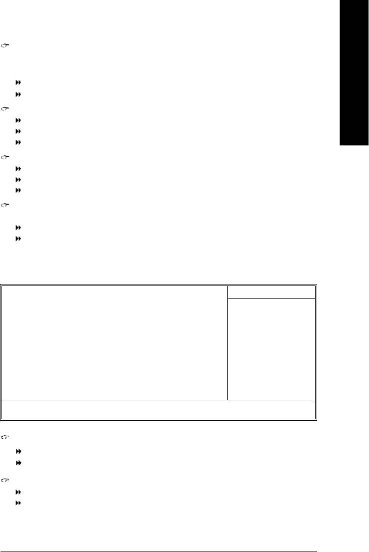
17) CLR_CMOS (Clear CMOS)
You may clear the CMOS data to its default values by this jumper. To clear CMOS, temporarily short
pins 1-2. Default doesn't include a jumper on pins 1-2 to prevent improper use of this header.
English
1
Open: Normal
1
Short: Clear CMOS
18) PWR_LED
PWR_LED is connected with the system power indicator to indicate whether the system is on/off. It
will blink when the system enters suspend mode. If you use dual color LED, power LED will turn to
another color.
Pin No. Definition
1 MPD+
2 MPD-
1
3 MPD-
8I845GE-RZ Series Motherboard
- 20 -

English
Chapter 2 BIOS Setup
Chapter 2 provides an overview of the BIOS Setup Program, which allows users to modify the basic
system configurations. This type of information is stored in battery-backed CMOS RAM so that it retains
the Setup information when the power is turned off.
ENTERING BIOS Setup
Turning on the computer and pressing <Del> immediately allow you to enter BIOS Setup. If you need
more advanced BIOS settings, please press Ctrl and F1 keys on the BIOS main screen to access the
the advanced BIOS settings.
CONTROL KEYS
< >< >< >< > Move to select item
<Enter> Select Item
<Esc> Main Menu - Quit and not save changes into CMOS Status Page Setup Menu
and Option Page Setup Menu - Exit current page and return to Main Menu
<+/PgUp> Increase the numeric value or make changes
<-/PgDn> Decrease the numeric value or make changes
<F1> General help, only for Status Page Setup Menu and Option Page Setup Menu
<F2> Item Help
<F5> Restore the previous CMOS value from CMOS, only for Option Page Setup Menu
<F6> Load the file-safe default CMOS value from BIOS default table
<F7> Load the Optimized Defaults
<F8> Q-Flash utility
<F9> System Information
<F10> Save all the CMOS changes, only for Main Menu
Main Menu
The on-line description of the highlighted setup function is displayed at the bottom of the screen.
Status Page Setup Menu / Option Page Setup Menu
Press F1 to pop up a small help window that describes the appropriate keys to use and the possible
selections for the highlighted item. To exit the Help Window, press <Esc>.
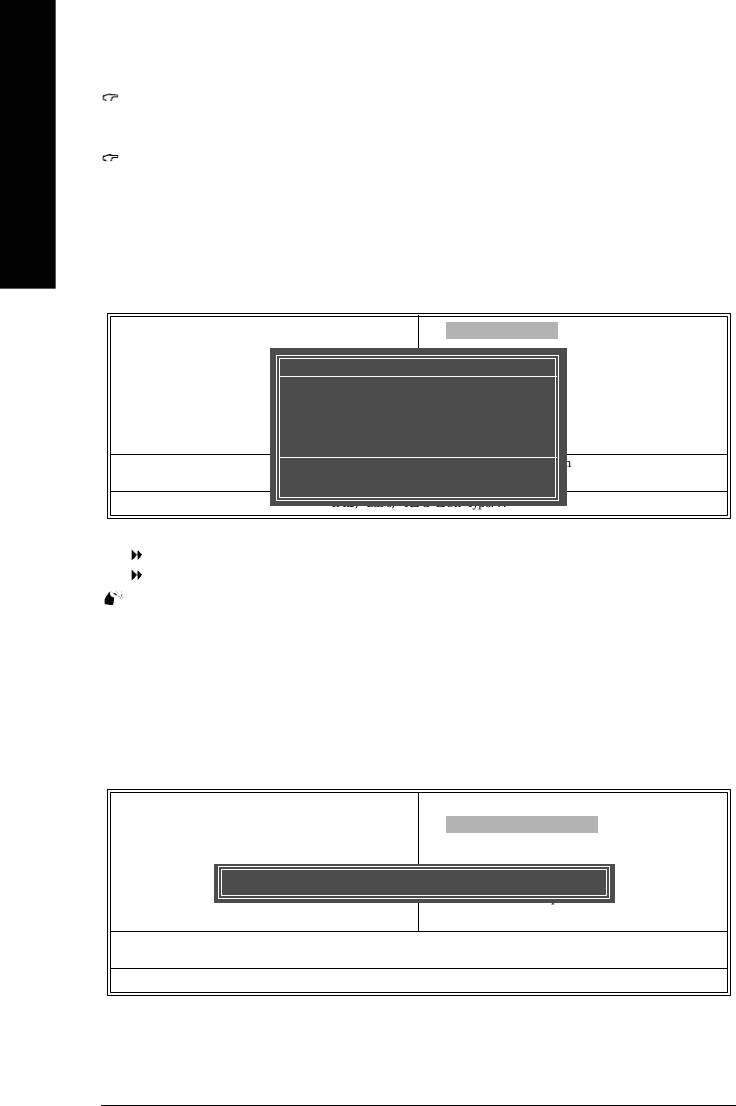
The Main Menu (For example: BIOS Ver. : F1)
Once you enter Award BIOS CMOS Setup Utility, the Main Menu (as figure below) will appear on the
screen. The Main Menu allows you to select from eight setup functions and two exit choices. Use
arrow keys to select among the items and press <Enter> to accept or enter the sub-menu.
CMOS Setup Utility-Copyright (C) 1984-2004 Award Software
} Standard CMOS Features
Top Performance
} Advanced BIOS Features
Load Fail-Safe Defaults
} Integrated Peripherals
Load Optimized Defaults
} Power Management Setup
Set Supervisor Password
} PnP/PCI Configurations
Set User Password
} PC Health Status
Save & Exit Setup
} Frequency/Voltage Control
Exit Without Saving
Ese: Quit higf: Select Item
F8: Q-Flash F10: Save & Exit Setup
Time, Date, Hard Disk Type...
- 21 - BIOS Setup

If you can't find the settings you want, press Ctrl and F1 in BIOS main menu to
access the hidden advanced options.
• Standard CMOS Features
English
This setup page includes all the items in standard compatible BIOS.
• Advanced BIOS Features
This setup page includes all the items of Award special enhanced features.
• Integrated Peripherals
This setup page includes all onboard peripherals settings.
• Power Management Setup
This setup page includes all the items of Green function features.
• PnP/PCI Configurations
This setup page includes all the configurations of PCI & PnP ISA resources.
• PC Health Status
This setup page includes the information of the system auto-detected temperature, voltage, and
fan speed.
• Frequency/Voltage Control
This setup page allows to control CPU clock and frequency ratio.
• Top Performance
If you wish to maximize the performance of your system, try to enable Top Performance.
• Load Fail-Safe Defaults
Fail-Safe Defaults indicates the value of the system parameters with which the system would be
in safe configuration.
• Load Optimized Defaults
Optimized Defaults indicates the value of the system parameters which the system would be in
best performance configuration.
• Set Supervisor Password
Change, set, or disable password. It allows you to limit access to the system and BIOS Setup, or
just to BIOS Setup.
• Set User Password
Change, set, or disable password. It allows you to limit access to the system.
• Save & Exit Setup
Save CMOS value settings to CMOS and exit BIOS Setup.
• Exit Without Saving
Abandon all CMOS value changes and exit BIOS Setup.
- 22 -8I845GE-RZ Series Motherboard

English
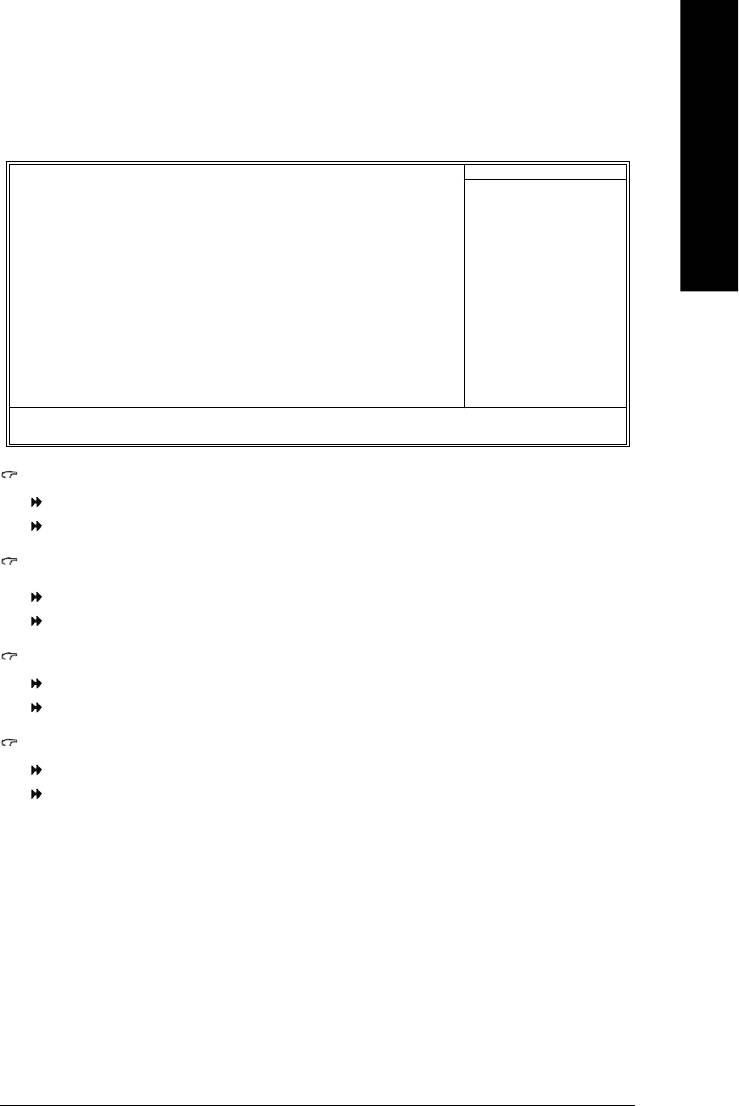
Standard CMOS Features
CMOS Setup Utility-Copyright (C) 1984-2004 Award Software
Standard CMOS Features
Date (mm:dd:yy) Fri, Jan 9 2004
Item Help
Time (hh:mm:ss) 22:31:24
Menu Level }
Change the day, month,
} IDE Primary Master [None]
year
} IDE Primary Slave [None]
} IDE Secondary Master [None]
<Week>
} IDE Secondary Slave [None]
Sun. to Sat.
Drive A [1.44M, 3.5"]
<Month>
Drive B [None]
Jan. to Dec.
Floppy 3 Mode Support [Disabled]
<Day>
Halt On [All, But Keyboard]
1 to 31 (or maximum
allowed in the month)
Base Memory 640K
Extended Memory 127M
<Year>
Total Memory 128M
1999 to 2098
higf: Move Enter: Select +/-/PU/PD: Value F10: Save ESC: Exit F1: General Help
F5: Previous Values F6: Fail-Safe Defaults F7: Optimized Defaults
Date
The date format is <week>, <month>, <day>, <year>.
Week From Sun. to Sat., determined by the BIOS and for display only.
Month From Jan. to Dec.
Day From 1st to 31st (or the maximum allowed in the month).
Year From Year 1999 to 2098.
Time
The format used to express time is hours:minutes:seconds. The time is calculated based on the
24-hour military-time clock. For example, 1 p.m. is 13:00:00.
IDE Primary Master, Slave / IDE Secondary Master, Slave
IDE HDD Auto-Detection Press "Enter" to select this option for automatic device detection.
IDE Primary/Secondary Master(Slave) setup You can use one of the three methods below:
Auto Allows BIOS to automatically detect IDE devices during POST. (Default value)
None Select this if no IDE devices are used and the system will skip the automatic
detection step and allow for faster system start up.
Manual User can manually input the correct settings
Access Mode Use this to set the access mode for the hard drive. The four options are:
CHS/LBA/Large/Auto (Default:Auto)
Hard drive information should be labeled on the outside drive casing.
Enter the appropriate option based on this information.
Capacity Capacity of currently installed hard disk.
Cylinder Number of cylinders
Head Number of heads
Precomp Write precomp
Landing Zone Landing zone
Sector Number of sectors
- 23 - BIOS Setup

Drive A / Drive B
The category identifies the types of floppy disk (drive A and drive B) installed in the computer.
None No floppy disk is installed
360K, 5.25" 5.25 inch PC-type standard drive; 360K byte capacity.
1.2M, 5.25" 5.25 inch AT-type high-density drive; 1.2M byte capacity
English
(3.5 inch when 3 Mode is Enabled).
720K, 3.5" 3.5 inch double-sided drive; 720K byte capacity
1.44M, 3.5" 3.5 inch double-sided drive; 1.44M byte capacity.
2.88M, 3.5" 3.5 inch double-sided drive; 2.88M byte capacity.
Floppy 3 Mode Support (for Japan Area)
Disabled Normal Floppy Drive. (Default value)
Drive A Enable Drive A 3 Mode support.
Drive B Enable Drive B 3 Mode support.
Both Enable both Drive A and B 3 Mode support.
Halt on
The category determines whether the computer will stop if an error is detected during power up.
All Errors Whenever the BIOS detects a non-fatal error the system will stop.
No Errors The system boot will not stop for any error that may be detected and you
will be prompted.
All, But Keyboard The system boot will not stop for a keyboard error; it will stop for all other
errors. (Default value)
All, But Diskette The system boot will not stop for a disk error; it will stop for all other errors.
All, But Disk/Key The system boot will not stop for a keyboard or disk error; it will stop for all
other errors.
Memory
The category is display-only which is determined by POST (Power On Self Test) of the BIOS.
Base Memory
The POST of the BIOS will determine the amount of base (or conventional) memory installed
in the system.
The value of the base memory is typically 512K for systems with 512K memory installed on
the motherboard, or 640K for systems with 640K or more memory installed on the motherboard.
Extended Memory
The BIOS determines how much extended memory is present during the POST.
This is the amount of memory located above 1 MB in the CPU's memory address map.
Total Memory
This item displays the memory size that used.
- 24 -8I845GE-RZ Series Motherboard

English
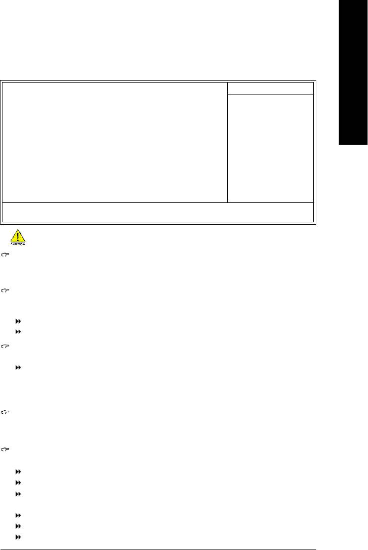
Advanced BIOS Features
CMOS Setup Utility-Copyright (C) 1984-2004 Award Software
Advanced BIOS Features
First Boot Device [Floppy]
Item Help
Menu Level }
Second Boot Device [HDD-0]
Third Boot Device [CDROM]
Select Boot Device
Priority
Boot Up Floppy Seek [Disabled]
Password Check [Setup]
[Floppy]
note 1
Boot from floppy
CPU Hyper-Threading
[Enabled]
note 2
Limit CPUID Max. to 3
[Enabled]
[LS120]
Init Display First [Onboard/AGP]
Boot from LS120
note 3
Graphics Aperture Size
[128MB]
[HDD-0]
note 4
Graphics Share Memory
[8M]
Boot from First HDD
[HDD-1]
Boot from second HDD
higf: Move Enter: Select +/-/PU/PD: Value F10: Save ESC: Exit F1: General Help
F5: Previous Values F6: Fail-Safe Defaults F7: Optimized Defaults
®
Note 1: This option appears only when the Intel Pentium
4 processor you install on the system supports
the Hyper-Threading Technology.
®
Note 2: This option is available only when you install an Intel
Prescott processor
Note 3/4: This option is available only when you use the onboard VGA function.
First / Second / Third Boot Device
Floppy Select your boot device priority by Floppy.
LS120 Select your boot device priority by LS120.
HDD-0~3 Select your boot device priority by HDD-0~3.
SCSI Select your boot device priority by SCSI.
CDROM Select your boot device priority by CDROM.
ZIP Select your boot device priority by ZIP.
USB-FDD Select your boot device priority by USB-FDD.
USB-ZIP Select your boot device priority by USB-ZIP.
USB-CDROM Select your boot device priority by USB-CDROM.
USB-HDD Select your boot device priority by USB-HDD.
LAN Select your boot device priority by LAN.
Disabled Select your boot device priority by Disabled.
Boot Up Floppy Seek
During POST, BIOS will determine the floppy disk drive installed is 40 or 80 tracks. 360K type is
40 tracks 720K, 1.2M and 1.44M are all 80 tracks.
Disabled BIOS will not search for the type of floppy disk drive by track number. Note
that there will not be any warning message if the drive installed is 360K.
(Default value)
Enabled BIOS searches for floppy disk drive to determine if it is 40 or 80 tracks. Note
that BIOS can not tell from 720K, 1.2M or 1.44M drive type as they are all 80
tracks.
- 25 - BIOS Setup

Password Check
Setup The system will boot but will not access to Setup page if the correct password
is not entered at the prompt. (Default value)
System The system will not boot and will not access to Setup page if the correct
English
password is not entered at the prompt.
CPU Hyper-Threading
®
This option is available only when you install an Intel
Hyper-Threading processor.
Disabled Disable CPU Hyper Threading.
Enabled Enable CPU Hyper Threading Feature. Please note that this feature is only
working for operating system with multi processors mode supported.
(Default value)
Limit CPUID Max. to 3
®
This option is available only when you install an Intel
Prescott processor.
Enabled Limit CPUID Maximum value to 3 when using older OS like NT4. (Defaults
value)
Disabled Disable CPUID Limit for Windows XP.
Init Display First
Select the first initation of the monitor display from onboard/AGP or PCI VGA card.
PCI Set Init Display First to PCI.
Onboard/AGP Set Init Display First to onboard/AGP. (Default value)
Graphics Aperture Size
This option is available only when you use the onboard VGA function.
128MB Set Graphics Aperture Size to 128MB. (Default value)
Disabled Disable this function.
Graphics Share Memory
This option is available only when you use the onboard VGA function.
8MB Set Graphics Share Memory to 8MB. (Default value)
1MB Set Graphics Share Memory to 1MB.
- 26 -8I845GE-RZ Series Motherboard

English
Integrated Peripherals
CMOS Setup Utility-Copyright (C) 1984-2004 Award Software
Integrated Peripherals
On-Chip Primary PCI IDE [Enabled]
Item Help
On-Chip Secondary PCI IDE [Enabled]
Menu Level u
IDE1 Conductor Cable [Auto]
IDE2 Conductor Cable [Auto]
If a hard disk
USB Controller [Enabled]
controller card is
used, set at Disabled
USB Keyboard Support [Disabled]
USB Mouse Support [Disabled]
[Enabled]
AC97 Audio [Auto]
Enable onboard IDE
*
Onboard H/W LAN
[Enabled]
PORT
*
Onboard LAN Boot ROM
[Disabled]
[Disabled]
Onboard Serial Port 1 [3F8/IRQ4]
Disable onboard IDE
Onboard Serial Port 2 [2F8/IRQ3]
PORT
Onboard Parallel Port [378/IRQ7]
Parallel Port Mode [SPP]
x ECP Mode Use DMA 3
Game Port Address [201]
Midi Port Address [Disabled]
x Midi Port IRQ 10
higf: Move Enter: Select +/-/PU/PD: Value F10: Save ESC: Exit F1: General Help
F5: Previous Values F6: Fail-Safe Defaults F7: Optimized Defaults
On-Chip Primary PCI IDE
Enabled Enable onboard 1st channel IDE port. (Default value)
Disabled Disable onboard 1st channel IDE port.
On-Chip Secondary PCI IDE
Enabled Enable onboard 2nd channel IDE port. (Default value)
Disabled Disable onboard 2nd channel IDE port.
IDE1 Conductor Cable
Auto BIOS autodetects IDE1 conductor cable. (Default Value)
ATA66/100 Set IDE1 Conductor Cable to ATA66/100 (80-pin). Please make sure your IDE
device and cable is compatible with ATA66/100.
ATA33 Set IDE1 Conductor Cable to ATA33 (40-pin). Please make sure your IDE
device and cable is compatible with ATA33.
IDE2 Conductor Cable
Auto BIOS autodetects IDE2 conductor cable. (Default Value)
ATA66/100 Set IDE2 Conductor Cable to ATA66/100 (80-pin). Please make sure your IDE
device and cable is compatible with ATA66/100.
ATA33 Set IDE2 Conductor Cable to ATA33 (40-pin). Please make sure your IDE
device and cable is compatible with ATA33.
USB Controller
Enabled Enable USB Controller. (Default value)
Disabled Disable USB Controller.
"*" For 8I845GE-RZ only.
- 27 - BIOS Setup

USB Keyboard Support
Enabled Enable USB Keyboard Support.
Disabled Disable USB Keyboard Support. (Default value)
English
USB Mouse Support
Enabled Enable USB Mouse Support.
Disabled Disable USB Mouse Support. (Default value)
AC97 Audio
Auto Autodetect onboard AC'97 audio function. (Default value)
Disabled Disable this function.
Onboard H/W LAN *
Enabled Enabled onboard LAN function. (Default value)
Disabled Disable this function.
Onboard LAN Boot ROM *
Enabled Enable to invoke the boot ROM of the onboard LAN chip.
Disabled Disable this function. (Default value)
Onboard Serial Port 1
Disabled Disable onboard Serial port 1.
3F8/IRQ4 Enable onboard Serial port 1 and address is 3F8/IRQ4. (Default value)
2F8/IRQ3 Enable onboard Serial port 1 and address is 2F8/IRQ3.
3E8/IRQ4 Enable onboard Serial port 1 and address is 3E8/IRQ4.
2E8/IRQ3 Enable onboard Serial port 1 and address is 2E8/IRQ3.
Auto BIOS will automatically setup the Port 1 address.
Onboard Serial Port 2
Disabled Disable onboard Serial port 2
3F8/IRQ4 Enable onboard Serial port 2 and address is 3F8/IRQ4.
2F8/IRQ3 Enable onboard Serial port 2 and address is 2F8/IRQ3. (Default value)
3E8/IRQ4 Enable onboard Serial port 2 and address is 3E8/IRQ4.
2E8/IRQ3 Enable onboard Serial port 2 and address is 2E8/IRQ3.
Auto BIOS will automatically setup the Port 2 address. .
Onboard Parallel Port
Disabled Disable onboard LPT port.
378/IRQ7 Enable onboard LPT port and address is 378/IRQ7. (Default Value)
278/IRQ5 Enable onboard LPT port and address is 278/IRQ5.
3BC/IRQ7 Enable onboard LPT port and address is 3BC/IRQ7.
Parallel Port Mode
SPP Use Parallel port as Standard Parallel Port. (Default Value)
EPP Use Parallel port as Enhanced Parallel Port.
ECP Use Parallel port as Extended Capabilities Port.
ECP+EPP Use Parallel port as ECP & EPP mode.
"*" For 8I845GE-RZ only.
- 28 -8I845GE-RZ Series Motherboard
English
ECP Mode Use DMA
This feature allows you to select Direct Memory Access(DMA) channel if the ECP mode selected.
This option is available only when Parallel Port Mode is set to ECP or ECP+EPP.
1 Set ECP Mode Use DMA to 1.
3 Set ECP Mode Use DMA to 3. (Default value)
Game Port Address
Disabled Disable this function
201 Enable this function and set gameport address to 201. (Default value)
209 Enable this function and set gameport address to 209.
Midi Port Address
Disabled Disable this function. (Default value)
330 Enable this function and set midiport address to 330.
300 Enable this function and set midiport address to 300.
Midi Port IRQ
This option is available when the Midi Port Address is not set to "Disabled."
5 Set midiport IRQ to 5.
10 Set midiport IRQ to 10. (Default value)
Power Management Setup
CMOS Setup Utility-Copyright (C) 1984-2004 Award Software
Power Management Setup
ACPI Suspend Type [S1(POS)]
Item Help
Power LED in S1 state [Blinking]
Menu Level u
Soft-Off by PWR-BTTN [Instant-Off]
[S1]
PME Event Wake Up [Enabled]
Set suspend type to
ModemRingOn [Enabled]
Power On Suspend under
Resume by Alarm [Disabled]
ACPI OS
x Date (of Month) Alarm Everyday
x Time (hh:mm:ss) Alarm 0 : 0 : 0
Power On by Mouse [Disabled]
[S3]
Power On by Keyboard [Disabled]
Set suspend type to
x KB Power ON Password Enter
Suspend to RAM under
AC BACK Function [Soft-Off]
ACPI OS
higf: Move Enter: Select +/-/PU/PD: Value F10: Save ESC: Exit F1: General Help
F5: Previous Values F6: Fail-Safe Defaults F7: Optimized Defaults
ACPI Suspend Type
S1(POS) Set ACPI suspend type to S1. (Default Value)
S3(STR) Set ACPI suspend type to S3.
Power LED in S1 state
Blinking The Power LED will be blinking during S1 state. (Default value)
Dual/OFF The Power LED will be turned off or change color.
- 29 - BIOS Setup

Soft-off by PWR-BTTN
Instant -Off Once a user presses the power button, the system will be turned off instantly.
(Default Value)
Delay 4 sec. Press power button for 4 seconds to turn off the system. System enters suspend
English
mode if the power button is pressed for less than 4 seconds.
PME Event Wake Up
Disabled Disable this function.
Enabled Enable PME Event Wake up. (Default Value)
ModemRingOn
Disabled Disable Modem Ring on function.
Enabled Enable Modem Ring on function. (Default Value)
Resume by Alarm
You can enable Resume by Alarm and key in month/date/time to turn on system.
Disabled Disable this function. (Default Value)
Enabled Enable alarm function to POWER ON system.
If Resume by Alarm is Enabled.
Date (of Month) Alarm:Everyday, 0~31
Time ( hh: mm: ss) Alarm: (0~23) : (0~59) : (0~59)
Power On by Mouse
Double Click Double-click the mouse to turn on the system.
Disabled Disable this function. (Default Value)
Power On by Keyboard
Keyboard 98 If your keyboard has a “Power” button, enable this function to press the button to
turn off the system.
Password Input password (from 1 to 5 characters) and press Enter to set the Keyboard
Power On Password.
Disabled Disable this function. (Default Value)
KB Power On Password
When "Power On by Keyboard" is set at Password, you can set the password here.
Enter Input password (from 1 to 5 characters) and press Enter to set the Keyboard
Power On password.
AC BACK Function
Soft-Off When AC-power back to the system, the system will be in "Off" state.
(Default value)
Full-On When AC-power back to the system, the system always in "On" state.
Memory When AC-power back to the system, the system will return to the Last state
before AC-power off.
- 30 -8I845GE-RZ Series Motherboard
English
PnP/PCI Configurations
CMOS Setup Utility-Copyright (C) 1984-2004 Award Software
PnP/PCI Configurations
PCI1/5 IRQ Assignment [Auto]
Item Help
PCI2 IRQ Assignment [Auto]
Menu Level }
PCI3 IRQ Assignment [Auto]
PCI4 IRQ Assignment [Auto]
Device(s) using this
INT:
USB 1.1 Host Cntrlr
-Bus 0 Dev29 Func 2
higf: Move Enter: Select +/-/PU/PD: Value F10: Save ESC: Exit F1: General Help
F5: Previous Values F6: Fail-Safe Defaults F7: Optimized Defaults
PCI1/5 IRQ Assignment
Auto Auto assign IRQ to PCI 1/5. (Default value)
3,4,5,7,9,10,11,12,14,15 Set IRQ 3,4,5,7,9,10,11,12,14,15 to PCI 1/5.
PCI2 IRQ Assignment
Auto Auto assign IRQ to PCI 2. (Default value)
3,4,5,7,9,10,11,12,14,15 Set IRQ 3,4,5,7,9,10,11,12,14,15 to PCI 2.
PCI3 IRQ Assignment
Auto Auto assign IRQ to PCI 3. (Default value)
3,4,5,7,9,10,11,12,14,15 Set IRQ 3,4,5,7,9,10,11,12,14,15 to PCI 3.
PCI4 IRQ Assignment
Auto Auto assign IRQ to PCI 4. (Default value)
3,4,5,7,9,10,11,12,14,15 Set IRQ 3,4,5,7,9,10,11,12,14,15 to PCI 3.
- 31 - BIOS Setup

PC Health Status
CMOS Setup Utility-Copyright (C) 1984-2004 Award Software
PC Health Status
Reset Case Open Status [Disabled]
Item Help
English
Menu Level }
Case Opened No
Vcore 1.348V
[Disabled]
DDR25V 2.544V
Don't reset case
+3.3V 3.360V
open status
+12V 11.858V
Current CPU Temperature 27° C
[Enabled]
Current CPU FAN Speed 4821 RPM
Clear case open status
and set to be Disabled at
Current SYSTEM FAN Speed 0 RPM
next boot Disabled
CPU Warning Temperature [Disabled]
at next boot
CPU FAN Fail Warning [Disabled]
System FAN Fail Warning [Disabled]
higf: Move Enter: Select +/-/PU/PD: Value F10: Save ESC: Exit F1: General Help
F5: Previous Values F6: Fail-Safe Defaults F7: Optimized Defaults
Reset Case Open Status
Disabled Don’t reset case open status. (Default value)
Enabled Clear case open status at next boot.
Case Opened
If the case is closed, Case Opened will show "No."
If the case is opened, Case Opened will show "Yes."
If you want to reset Case Opened value, enable Reset Case Open Status and save the change
to CMOS, and then your computer will restart.
Current Voltage (V) Vcore/+3.3V/DDR25V /+12V
Detect system’s voltage status automatically.
Current CPU Temperature
Detect CPU Temp. automatically.
Current CPU/SYSTEM FAN Speed (RPM)
Detect CPU/SYSTEM Fan speed status automatically.
CPU Warning Temperature
Alarm occurs when the current CPU temperature is higher than the selected temperature.
o
o
o
o
60
C / 140
F Monitor CPU temperature at 60
C / 140
F.
o
o
o
o
70
C / 158
F Monitor CPU temperature at 70
C / 158
F.
o
o
o
o
80
C / 176
F Monitor CPU temperature at 80
C / 176
F.
o
o
o
o
90
C / 194
F Monitor CPU temperature at 90
C / 194
F.
Disabled Disable this function. (Default value)
CPU/SYSTEM FAN Fail Warning
Disabled Disable fan warning function . (Default value)
Enabled Enable fan warning function. Alarm occurs when FAN stops.
- 32 -8I845GE-RZ Series Motherboard
English
Frequency/Voltage Control
CMOS Setup Utility-Copyright (C) 1984-2004 Award Software
Frequency/Voltage Control
CPU Clock Ratio [15X]
Item Help
CPU Host Clock Control [Disabled]
x CPU Host Frequency (Mhz) 133
Menu Level }
x Fixed PCI/AGP Frequency 33/66
Host/DRAM Clock ratio [Auto]
Set CPU Ratio if CPU
Memory Frequency (Mhz) 333
Ratio is unclocked
PCI/AGP Frequency (Mhz) 33/66 AUTO
higf: Move Enter: Select +/-/PU/PD: Value F10: Save ESC: Exit F1: General Help
F5: Previous Values F6: Fail-Safe Defaults F7: Optimized Defaults
Incorrect using these features may cause your system broken. For power users only.
CPU Clock Ratio
This setup option will be automatically assigned by CPU detection.
The option will display "Locked" and read only if the CPU ratio is not changeable.
CPU Host Clock Control
Please note that if your system is overclocked and cannot restart, please wait 20 secs.
for automatic system restart or clear the CMOS setup data and perform a safe restart.
Disabled Disable CPU Host Clock Control. (Default value)
Enabled Enable CPU Host Clock Control.
CPU Host Frequency (Mhz)
This item will be available when "CPU Host Clock Control" is set to Enabled.
100MHz ~ 355MHz Set CPU Host Clock from 100MHz to 355MHz.
If you use a Pentium 4 CPU with FSB 533MHz, please set "CPU Clock" to 133MHz. For a P4 CPU
with FSB 400MHz, please set it to 100MHz.
Inappropriate using it may cause your system corrupted. For power End-User use only!
Fixed PCI/AGP Frequency
You can choose those modes to adjust PCI/AGP frequency. (Select PCI/AGP frequency
asynchronous with CPU frequency).
Host/DRAM Clock ratio
For FSB (Front Side Bus) frequency=400MHz,
2.0 Memory Frequency = Host clock X 2.0.
2.66 Memory Frequency = Host clock X 2.66.
Auto Set Memory frequency by DRAM SPD data. (Default value)
For FSB (Front Side Bus) frequency=533MHz,
2.0 Memory Frequency = Host clock X 2.0.
2.5 Memory Frequency = Host clock X 2.5.
Auto Set Memory frequency by DRAM SPD data. (Default value)
- 33 - BIOS Setup
Memory Frequency (Mhz)
The values depend on CPU Host Frequency.
PCI/AGP Frequency (Mhz)
English
The values depend on Fixed PCI/AGP Frequency.
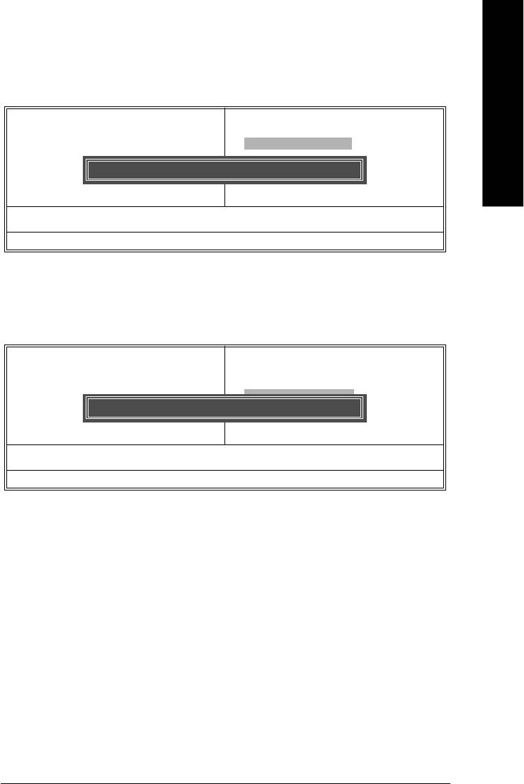
Top Performance
CMOS Setup Utility-Copyright (C) 1984-2004 Award Software
} Standard CMOS Features
Top Performance
} Advanced BIOS Features
Load Fail-Safe Defaults
} Integrated Peripherals
Top Performance
Load Optimized Defaults
} Power Management Setup
Set Supervisor Password
Disabled.........................[n ]
} PnP/PCI Configurations
Set User Password
Enabled..........................[ ]
} PC Health Status
Save & Exit Setup
} Frequency/Voltage Control
Exit Without Saving
Esc: Quit higf: Select Item
hi: Move ENTER: Accept
F8: Q-Flash F10: Save & Exit Setup
ESC: Abort
Time, Date, Hard Disk Type...
If you wish to maximize the performance of your system, enable "Top Performance."
Disabled Disable this function. (Default Value)
Enabled Enable Top Performance function.
"Top Performance" will increase H/W working speed. Different system configuration (both H/W
component and OS) will effect the result. For example, the same H/W configuration might not run
properly with Windows XP, but works smoothly with Windows NT. Therefore, if your system is not
perform enough, the reliability or stability problem will appear sometimes, and we will recommend you
disabling the option to avoid the problem as mentioned above.
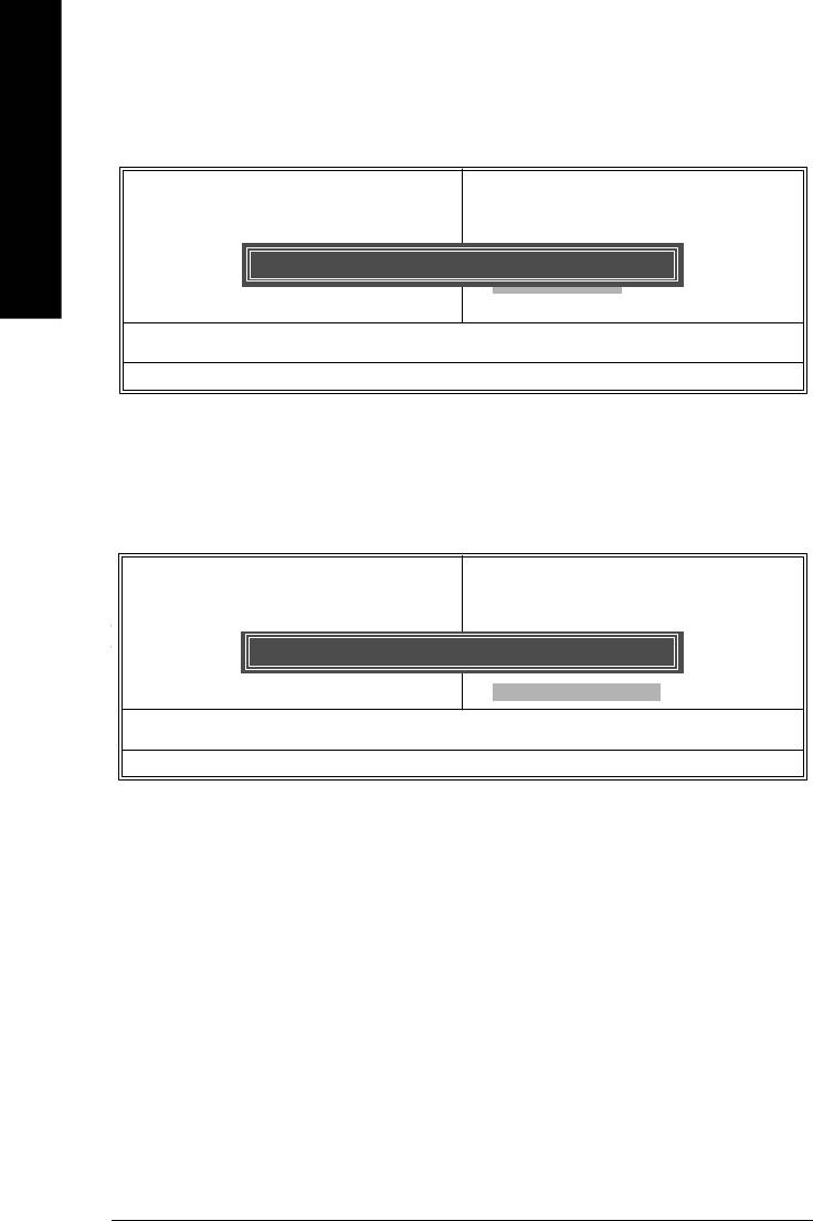
Load Fail-Safe Defaults
CMOS Setup Utility-Copyright (C) 1984-2004 Award Software
} Standard CMOS Features
Top Performance
} Advanced BIOS Features
Load Fail-Safe Defaults
} Integrated Peripherals
Load Optimized Defaults
} Power Management Setup
Set Supervisor Password
} PnP/PCI Configurations
Load Fail-Safe Defaults (Y/N)? N
Set User Password
} PC Health Status
Save & Exit Setup
} Frequency/Voltage Control
Exit Without Saving
Esc: Quit higf: Select Item
F8: Q-Flash F10: Save & Exit Setup
Load Fail-Safe Defaults
Fail-Safe defaults contain the most appropriate values of the system parameters that allow minimum
system performance.
- 34 -8I845GE-RZ Series Motherboard
English
Load Optimized Defaults
CMOS Setup Utility-Copyright (C) 1984-2004 Award Software
} Standard CMOS Features
Top Performance
} Advanced BIOS Features
Load Fail-Safe Defaults
} Integrated Peripherals
Load Optimized Defaults
} Power Management Setup
Set Supervisor Password
} PnP/PCI Configurations
Load Optimized Defaults (Y/N)? N
Set User Password
} PC Health Status
Save & Exit Setup
} Frequency/Voltage Control
Exit Without Saving
Esc: Quit higf: Select Item
F8: Q-Flash F10: Save & Exit Setup
Load Optimized Defaults
Selecting this field loads the factory defaults for BIOS and Chipset Features which the system automatically
detects.
Set Supervisor/User Password
CMOS Setup Utility-Copyright (C) 1984-2004 Award Software
Load Fail-Safe Defaults
} Standard CMOS Features
Top Performance
} Advanced BIOS Features
Load Fail-Safe Defaults
} Integrated Peripherals
Load Optimized Defaults
} Power Management Setup
Set Supervisor Password
} PnP/PCI Configurations
Enter Password:
Set User Password
} PC Health Status
Save & Exit Setup
} Frequency/Voltage Control
Exit Without Saving
Esc: Quit higf: Select Item
Load Fail-Safe Defaults (Y/N)? N
F8: Q-Flash F10: Save & Exit Setup
Change/Set/Disable Password
When you select this function, the following message will appear at the center of the screen to assist you
in creating a password.
Type the password, up to eight characters, and press <Enter>. You will be asked to confirm the password.
Type the password again and press <Enter>. You may also press <Esc> to abort the selection and not
enter a password.To disable password, just press <Enter> when you are prompted to enter password.
A message "PASSWORD DISABLED" will appear to confirm the password being disabled. Once the
password is disabled, the system will boot and you can enter Setup freely.
The BIOS Setup program allows you to specify two separate passwords:
SUPERVISOR PASSWORD and a USER PASSWORD. When disabled, anyone may access all BIOS
Setup program function. When enabled, the Supervisor password is required for entering the BIOS
Setup program and having full configuration fields, the User password is required to access only basic
items.
If you select "System" at "Password Check" in Advance BIOS Features Menu, you will be prompted
for the password every time the system is rebooted or any time you try to enter Setup Menu.
If you select "Setup" at "Password Check" in Advance BIOS Features Menu, you will be prompted only
when you try to enter Setup.you try to enter Setup.
- 35 - BIOS Setup
Save & Exit Setup
CMOS Setup Utility-Copyright (C) 1984-2004 Award Software
} Standard CMOS Features
Top Performance
English
} Advanced BIOS Features
Load Fail-Safe Defaults
} Integrated Peripherals
Load Optimized Defaults
} Power Management Setup
Set Supervisor Password
} PnP/PCI Configurations
Save to CMOS and EXIT (Y/N)? Y
Set User Password
} PC Health Status
Save & Exit Setup
} Frequency/Voltage Control
Exit Without Saving
Esc: Quit higf: Select Item
F8: Q-Flash F10: Save & Exit Setup
Save Data to CMOS
Type "Y" will quit the Setup Utility and save the user setup value to RTC CMOS.
Type "N" will return to Setup Utility.
Exit Without Saving
CMOS Setup Utility-Copyright (C) 1984-2004 Award Software
} Standard CMOS Features
Top Performance
} Advanced BIOS Features
Load Fail-Safe Defaults
} Integrated Peripherals
Load Optimized Defaults
Type "Y" will quit the Setup Utility without saving to RTC CMOS.
} Power Management Setup
Set Supervisor Password
Type "N" will return to Setup Utility.
} PnP/PCI Configurations
Quit Without Saving (Y/N)? N
Set User Password
} PC Health Status
Save & Exit Setup
} Frequency/Voltage Control
Exit Without Saving
Esc: Quit higf: Select Item
F8: Q-Flash F10: Save & Exit Setup
Abandon all Data
Type "Y" will quit the Setup Utility without saving to RTC CMOS.
Type "N" will return to Setup Utility.
- 36 -8I845GE-RZ Series Motherboard
English
Revision History
Chapter 3 Install Drivers
Install Drivers
Pictures below are shown in Windows XP
Insert the driver CD-title that came with your motherboard into your CD-ROM drive, the
driver CD-title will auto start and show the installation guide. If not, please double click the
CD-ROM device icon in "My computer", and execute the setup.exe.
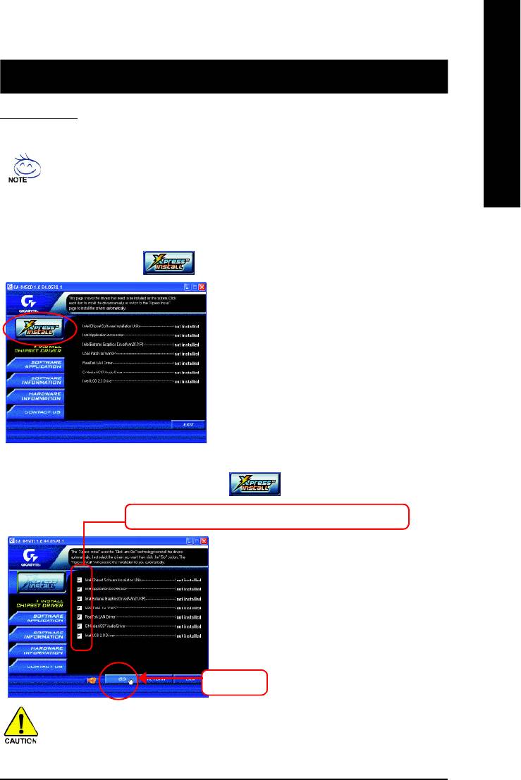
INSTALL CHIPSET DRIVER
This page shows the drivers that need to be installed for the system. Click each item to install the
driver manually or switch to the to install the drivers automatically.
Massage: Some device drivers will restart your
system automatically. After restarting your
system the "Xpress Install" will continue to install
other drivers.
The "Xpress Install" uses the"Click and Go" technology to install the drivers automatically. Just select
the drivers you want then click the "GO" button. The will execute the installation for you
by itself.
We recommend that you install all components in the list.
Click "GO".
For USB2.0 driver support under Windows XP operating system, please use Windows
Service Pack. After install Windows Service Pack, it will show a question mark "?" in
"Universal Serial Bus controller" under "Device Manager". Please remove the question
mark and restart the system (System will auto-detect the right USB2.0 driver).
- 37 -
Driver Installation

You have completed drivers installation.
English
Item Description
n Intel Chipset Software Installation Utility
Tell the operating system how the chipset components will be configured.
n Intel Application Accelerator
Designed to improve performance of the storage sub-system and overall system performance.
n Intel Extreme Graphics Driver (Win2K/XP)
®
For Intel
845G/GL/GE/GV Chipsets.
n USB Pacth for WinXP
This patch driver can help you to resolve the USB device wake up S3 hang up issue in XP.
n RealTek LAN Driver*
RealTek 10/100 LAN driver for 81xx series chips.
n C-Media AC97 Audio Driver
Install C-Media AC97 audio driver.
n Intel USB 2.0 Driver
It is recommended that you use the Microsoft Windows update for the most updated driver
for XP/2K.
"*" For 8I845GE-RZ only.
- 38 -8I845GE-RZ Series Motherboard

English
Contact Us
— Taiwan (Headquarters)
— Japan
GIGA-BYTE TECHNOLOGY CO., LTD.
NIPPON GIGA-BYTE CORPORATION
Address: No.6, Bau Chiang Road, Hsin-Tien, Taipei Hsien,
WEB address : http://www.gigabyte.co.jp
Taiwan
— Singapore
TEL: +886 (2) 8912-4888
GIGA-BYTE SINGAPORE PTE. LTD.
FAX: +886 (2) 8912-4003
Tech. Support :
Tech. Support :
http://tw.giga-byte.com/TechSupport/ServiceCenter.htm
http://tw.giga-byte.com/TechSupport/ServiceCenter.htm
Non-Tech. Support (Sales/Marketing) :
Non-Tech. Support (Sales/Marketing) :
http://ggts.gigabyte.com.tw/nontech.asp
http://ggts.gigabyte.com.tw/nontech.asp
— U.K.
WEB address (English): http://www.gigabyte.com.tw
G.B.T. TECH. CO., LTD.
WEB address (Chinese): http://chinese.giga-byte.com
Address: GUnit 13 Avant Business Centre 3 Third Avenue, Denbigh
— U.S.A.
West Bletchley Milton Keynes, MK1 1DR, UK, England
G.B.T. INC.
TEL: +44-1908-362700
Address: 17358 Railroad St, City of Industry, CA 91748.
FAX: +44-1908-362709
TEL: +1 (626) 854-9338
Tech. Support :
FAX: +1 (626) 854-9339
http://uk.giga-byte.com/TechSupport/ServiceCenter.htm
Tech. Support :
Non-Tech. Support (Sales/Marketing) :
http://www.giga-byte.com/TechSupport/ServiceCenter.htm
http://ggts.gigabyte.com.tw/nontech.asp
Non-Tech. Support (Sales/Marketing) :
WEB address : http://uk.giga-byte.com
http://ggts.gigabyte.com.tw/nontech.asp
— The Netherlands
WEB address : http://www.giga-byte.com
GIGA-BYTE TECHNOLOGY B.V.
— Germany
TEL: +31 40 290 2088
G.B.T. TECHNOLOGY TRADING GMBH
NL Tech.Support: 0900-GIGABYTE (0900-44422983)
Address: Friedrich-Ebert-Damm 112 22047 Hamburg
BE Tech.Support: 0900-84034
TEL: +49-40-2533040 (Sales)
FAX: +31 40 290 2089
+49-1803-428468 (Tech.)
Tech. Support :
FAX: +49-40-25492343 (Sales)
http://nz.giga-byte.com/TechSupport/ServiceCenter.htm
+49-1803-428329 (Tech.)
Non-Tech. Support (Sales/Marketing) :
Tech. Support :
http://ggts.gigabyte.com.tw/nontech.asp
http://de.giga-byte.com/TechSupport/ServiceCenter.htm
WEB address : http://www.giga-byte.nl
Non-Tech. Support (Sales/Marketing) :
http://ggts.gigabyte.com.tw/nontech.asp
WEB address : http://www.gigabyte.de
- 39 -
Contact Us

— China
— Australia
NINGBO G.B.T. TECH. TRADING CO., LTD.
GIGABYTE TECHNOLOGY PTY. LTD.
Tech. Support :
Address: 3/6 Garden Road, Clayton, VIC 3168 Australia
http://cn.giga-byte.com/TechSupport/ServiceCenter.htm
TEL: +61 3 85616288
Non-Tech. Support (Sales/Marketing) :
FAX: +61 3 85616222
English
http://ggts.gigabyte.com.tw/nontech.asp
Tech. Support :
WEB address : http://www.gigabyte.com.cn
http://www.giga-byte.com.au/TechSupport/ServiceCenter.htm
Shanghai
Non-Tech. Support (Sales/Marketing) :
TEL: +86-021-63410999
http://ggts.gigabyte.com.tw/nontech.asp
FAX: +86-021-63410100
WEB address : http://www.giga-byte.com.au
Beijing
— France
TEL: +86-010-82886651
GIGABYTE TECHNOLOGY FRANCES S.A.R.L.
FAX: +86-010-82888013
Tech. Support :
Wuhan
http://tw.giga-byte.com/TechSupport/ServiceCenter.htm
TEL: +86-027-87851061
Non-Tech. Support (Sales/Marketing) :
FAX: +86-027-87851330
http://ggts.gigabyte.com.tw/nontech.asp
GuangZhou
WEB address : http://www.gigabyte.fr
TEL: +86-020-87586074
— Russia
FAX: +86-020-85517843
Moscow Representative Office Of Giga-Byte Technology Co.,
Chengdu
Ltd.
TEL: +86-028-85236930
Tech. Support :
FAX: +86-028-85256822
http://tw.giga-byte.com/TechSupport/ServiceCenter.htm
Xian
Non-Tech. Support (Sales/Marketing) :
TEL: +86-029-85531943
http://ggts.gigabyte.com.tw/nontech.asp
FAX: +86-029-85539821
WEB address : http://www.gigabyte.ru
Shenyang
— Poland
TEL: +86-024-23960918
Representative Office Of Giga-Byte Technology Co., Ltd.
FAX: +86-024-23960918-809
POLAND
Tech. Support :
http://tw.giga-byte.com/TechSupport/ServiceCenter.htm
Non-Tech. Support (Sales/Marketing) :
http://ggts.gigabyte.com.tw/nontech.asp
WEB address : http://www.gigabyte.pl
- 40 -8I845GE-RZ Series Motherboard


