Gigabyte 8S661FXME-RZ: Hardware Installation Process
Hardware Installation Process: Gigabyte 8S661FXME-RZ
English
Hardware Installation Process
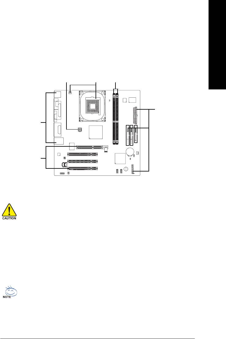
To set up your computer, you must complete the following steps:
Step 1- Install the Central Processing Unit (CPU)
Step 2- Installation of Memory
Step 3- Installation of Expansion Cards
Step 4- Installation of I/O Peripherals Cables
Step 1
Step 2Step 4
Step 4
Step 4
Step 3
Step 1: Install the Central Processing Unit (CPU)
Before installing the CPU, please comply with the following conditions:
1. Please make sure that the motherboard supports the CPU.
2. Please take note of the one indented corner of the CPU. If you install the CPU in the
wrong direction, the CPU will not insert properly. If this occurs, please change the insert
direction of the CPU.
3. Please add an even layer of heat sink paste between the CPU and heatsink.
4. Please make sure the heatsink is installed on the CPU prior to system use, otherwise
overheating and permanent damage of the CPU may occur.
5. Please set the CPU host frequency in accordance with the processor specifications. It is
not recommended that the system bus frequency be set beyond hardware specifications
since it does not meet the required standards for the peripherals. If you wish to set the
frequency beyond the proper specifications, please do so according to your hardware
specifications including the CPU, graphics card, memory, hard drive, etc.
HT functionality requirement content :
Enabling the functionality of Hyper-Threading Technology for your computer system
requires all of the following platform components:
®
- CPU: An Intel
Pentium 4 Processor with HT Technology
®
- Chipset: An Intel
Chipset that supports HT Technology
- BIOS: A BIOS that supports HT Technology and has it enabled
- OS: An operation system that has optimizations for HT Technology
- 9 -
Hardware Installation Process

Step 1-1: Installation of the CPU
Fig. 1
Socket lever
Position lever at a 90 degree angle.
English
Fig. 2
A gold-colored triangle is marked one edge of the CPU. Please align
this edge with the socket edge closest to the CPU lever. Gently place
the CPU into position making sure that the CPU pins fit perfectly into their
holes. Once the CPU is positioned into it socket, place one finger down
on the middle of the CPU and gently press the metal lever back into its
original position.
Please use extra care when installing the CPU. The CPU will not fit if positioned
incorrectly. Rather than applying force, please change the positioning of the
CPU.
Step 1-2: Installation of the Heatsink
Fig.1
Before installing the heat sink, please first add an even layer of heat sink
paste on the surface of the CPU.
Fig.2
Install all the heat sink components (Please refer to the heat sink manual
for detailed installation instructions).
Fig.3
Please connect the heat sink power connector to the CPU_FAN con-
nector located on the motherboard so that the heat sink can properly
function to prevent CPU overheating.
The heat sink may adhere to the CPU as a result of hardening of the heat sink
paste. To prevent such an occurrence, it is suggested that either thermal tape
rather than heat sink paste be used for heat dissipation or using extreme care
when removing the heat sink.
- 10 -8S661FXME-RZ Motherboard
Оглавление
- Features Summary
- 8S661FXME-RZ Motherboard Layout
- Block Diagram
- Hardware Installation Process
- Step 2: Installation of Memory
- Step 3: Installation of Expansion Cards
- The Main Menu (For example: BIOS Ver. : F1)
- Standard CMOS Features
- Advanced BIOS Features
- Integrated Peripherals
- Power Management Setup
- PnP/PCI Configurations
- PC Health Status
- MB Intelligent Tweaker(M.I.T.)
- Select Language
- Set Supervisor/User Password
- Save & Exit Setup
- Revision History


