Ardo DP36 – страница 2
Инструкция к Плите Ardo DP36

FR
Pour l'utilisateur
inverse à la marche des aiguilles d’une
veut allumer.
montre jusqu’à la position "maximum";
Si l'allumage électrique est difficile pour
- approcher une allumette du trou central de
quelques types de gaz, il est conseillé
la sole du four et appuyer à fond sur la
d'effectuer l'opération avec la manette sur
manette (voir fig. 9);
position "minimum" (flamme au ralenti).
- vérifier l'allumage par le trou central de la
- Pour les cuisinières équipées de
sole en continuant à appuyer sur la manette;
dispositif d'allumage électrique des
- après 10 secondes environs, lâcher la ma-
brûleurs du four et grilloir, il faut
nette et s’assurer que le brûleur reste
absolument allumer ces brûleurs avec
allumé. Dans le cas contraire, répéter
la porte du four complètement ouverte;
l’opération.
- Pendant l'allumage des brûleurs de four et
grilloir qui sont équipés d'un dispositif
ALLUMAGE DU BRULEUR DE GRILLOIR
d'allumage électrique, ce dispositif ne doit
(GRILLOIR A GAZ)
pas être actionné pendant plus de 10
- Placer la protection manette selon la figure
secondes. Si au bout de 10 secondes le
12;
brûleur ne s'est pas allumé, cesser d'agir
- appuyer sur la manette du four et la tourner
sur le dispositif, laisser la porte ouverte et
vers la droite jusqu'à l'arrêt;
attendre au moins une minute avant toute
- approcher une allumette du tuyau perforé
nouvelle tentative d'allumage du brûleur. Si
du brûleur et appuyer à fond sur la manet-
le disfonctionnement se répète, il faut
te (voir fig. 10);
allumer le brûleur manuellement et
- vérifier l'allumage du brûleur en continuant
consulter votre service après-vente.
à appuyer sur la manette;
ATTENTION
- après 10 secondes environs, lâcher la ma-
- Après une certain période d'inactivité de la
nette et s’assurer que le brûleur reste
cuisinière il peut arriver que l'allumage des
allumé. Dans le cas contraire, répéter
brûleurs ne soit pas instantané, c'est
l’opération.
normal. Quelques secondes sont
nécessaires pour que l'air accumulé dans
DISPOSITIF DE SECURITE
les tubes soit expulsé;
Les brûleurs qui sont équipés de ce dispositif
- en tous cas, il faut éviter une fuite excessive
ont l'avantage d'être protégés en cas
du gaz non brûlé. Si l’allumage n'a pas lieu
d'extinction accidentelle. En effet, dans ce
pendant un temps relativement court, il faut
cas, le dispositif bloque l'alimentation en gaz
positionner de nouveau la manette sur le
du brûleur, évitant de cette façon une
repère de fermeture ( ) et répéter
accumulation dangereuse de gaz non brûlé:
l'opération;
dès l'extinction, il ne doit pas s'écouler plus
- lorsqu'on emploie le four et le grilloir pour
de 60 secondes pour les brûleurs du four et
la première fois, il peut y avoir dégagement
du grilloir ou 90 secondes pour les brûleurs
de fumée et une odeur particulière. Cela
de la table de cuisson.
est dû au traitement des surfaces et aux
résidus huileux sur les brûleurs.
CUISINIERES AVEC ALLUMAGE
ELECTRIQUE
UTILISATION DES FEUX DE LA TABLE DE
Se reporter aux instructions ci-dessus, sauf
CUISSON
que l’allumette est remplacée par une
Utiliser des récipients qui ont un diamètre
étincelle qui jaillit en appuyant, même
approprié pour le type du brûleur. En effet
plusieurs fois, sur le bouton sur le bandeau,
les flammes ne doivent pas dépasser le fond
ou en appuyant la manette du brûleur, qu'on
des casseroles. On conseille:
21
FR
Pour l'utilisateur
- pour brûleur auxiliaire = récipient de 8 cm
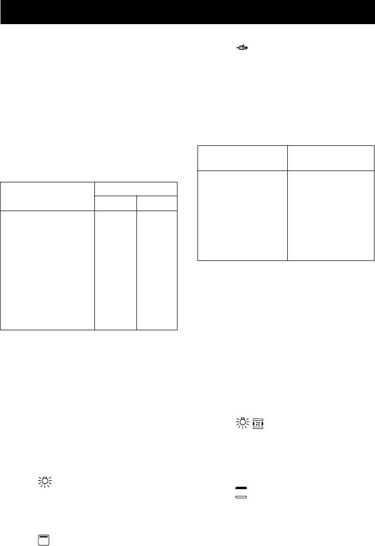
Position manette Température
au moins
thermostat en°C
- pour brûleur semi-rapide= récipient de 14
1 150
cm au moins
2 170
- pour brûleur rapide = récipient de 22 cm
3 190
au moins
4 210
NOTE: Il ne faut pas laisser la manette entre
5 230
les repères
et ( ).
6 250
7 270
UTILISATION DES PLAQUES
ELECTRIQUES
IMPORTANT: Ne pas utiliser la lèche-frite
Les différentes allures de chauffe
comme plat à cuire, elle sert uniquement
s’obtiennent de la façon suivante:
pour contenir l'huile ou la graisse tombant
- posit. 1 = intensité minimum pour toutes
des mets pendant la cuisson au grilloir.
les plaques;
NOTE: Pour cuisinières sans thermostat:
- posit. 6 = intensité maximum pour plaques
- manette en position "maximum" = 270°C
normales et plaques rapides (avec disque
- manette en position "minimum"
= 150°C
rouge);
- Toutes les autres températures entre 150°C
- posit. 0 = fermé
et 270°C sont à rechercher entre les
Les récipients utilisés doivent avoir un
repères de minimum et maximum.
diamètre suffisamment grand pour couvrir la
Il ne faut pas laisser la manette entre les
surface des plaques et un fond plat (voir fig.
repères
et ( ).
11).
ATTENTION:
UTILISATION DU GRILLOIR A GAZ OU
- Il ne faut pas faire fonctionner les plaques
ELECTRIQUE
sans casseroles au dessus, sauf la
- placer la protection manettes (voir fig. 12);
première fois, pour 10 minutes environ pour
- allumer le brûleur et attendre quelques
faire sécher les résidus d’huile ou
minutes afin que le brûleur se réchauffe ou
d’humidité;
mettre en marche la résistance;
- si la plaque doit rester inutilisée pour
- poser les mets à cuire sur la grille-support
longtemps, enduire modérément la surface
du four;
vernie;
- introduire le tout dans le four en utilisant le
- éviter les encrassements pour ne pas avoir
gradin le plus haut;
à utiliser d'abrasif.
- placer la lèche-frite sur le gradin le plus bas;
- fermer doucement la porte en l'adossant à
UTILISATION DU FOUR A GAS
la protection manettes;
- Après l’allumage du brûleur, préchauffer le
- après quelques minutes retourner les mets
four pendant 10 minutes;
pour exposer l’autre côté aux rayons
- placer les mets à cuire dans un plat et le
infrarouges émis par le brûleur.
mettre sur la grille chromée;
NOTE: Lorsqu’on emploie le grilloir pour la
- introduire le tout dans le four en utilisant le
première fois il peut y avoir dégagement de
troisième gradin et tourner la manette sur
fumée, il faut donc attendre que tous les
la graduation désirée;
résidus d’huile soient brûlés avant
- on peut contrôler la cuisson à travers le
d’introduire les mets.
hublot de la porte et avec le four éclairé.
Le grilloir doit seulement être utilisé à son
Eviter d’ouvrir la porte, sauf pour
débit calorifique nominal.
assaisonner les mets.
22
FR
Pour l'utilisateur
ATTENTION: les parties accessibles peuvent
plafond du four).
être chaudes pendant le fonctionnement
- repère : chauffage du grilloir avec
du grilloir! Eloigner les jeunes enfants.
fonctionnement du tournebroche.
En tournant la manette du thermostat dans
La remise à 0 (éteint) s’effectue en tournant
le sens des aiguilles d’une montre jusqu'au
la manette dans le sens inverse des aiguilles
repère du grilloir sur le bandeau, la résistance
d’une montre.
du grilloir, placée en haut dans le four, se met
NOTE - Le voyant jaune s’allume lorsque le
en marche.
thermostat intervient.
Le voyant rouge s'allume pour signaler que
Avant d'introduire les mets à cuire, préchauffer
la résitance est sous tension.
le four pendant 10 minutes au moins.
Le tableau ci-dessous est donné à titre indicatif
(une adaptation est à réaliser en fonction de
Position manette Température
la qualité, la quantité et les goûts de chacun):
thermostat en°C
1 60
Mets à griller Temps en minutes
2 80
3110
1° Côté 2° Côté
4 140
5 170
Viande mince 6 4
6 200
Viande modérément
7 220
épaisse 8 5
8 250
Poisson mince et
sans écailles 10 8
FOUR ELECTRIQUE A CHALEUR
Poisson modérément
TOURNANTE
volumineux 15 12
- La grille du four sert pour supporter les plats
Saucisse 12 10
ou directement la viande à cuire.
Toasts 5 2
- la lèche-frite sert uniquement pour recueillir
Petits oiseaux 20 15
le jus ou la graisse tombant des mets. Ne
pas l'utiliser directement pour cuire.
FOUR ELECTRIQUE STATIQUE
La mise en marche du four ou du grilloir
- La grille du four sert pour supporter les plats
s’effectue au moyen d’une seule manette.
ou directement la viande à cuire.
Partant de la position 0 (fermé) et en tournant
- la lèche-frite sert uniquement pour recueillir
la manette dans le sens des aiguilles d’une
le jus ou la graisse tombant des mets. Ne
montre, on assure successivement les
pas l'utiliser directement pour cuire.
opérations suivantes:
La mise en marche du four ou du grilloir
- repère : éclairage de la lampe du
s’effectue au moyen d’une seule manette.
Partant de la position 0 (fermé) et en tournant
four (elle restera toujours allumée sur toutes
la manette dans le sens des aiguilles d’une
les différentes positions de la manette) e
montre, on assure successivement les
et fonctionnement du ventilateur.
opérations suivantes:
- repères de 60 à 220°C: chauffage du four
avec régulation par thermostat.
- repère
: éclairage de la lampe du four
(elle restera toujours allumée sur toutes les
- repère
: allumage du grilloir (sur le
différentes positions de la manette).
plafond du four).
- repères 1 à 8 (ou de 60 à 250°C): chauffage
La remise à 0 (éteint) s’effectue en tournant
du four avec régulation par thermostat.
la manette dans le sens inverse des aiguilles
- repère
: allumage du grilloir (sur le
d’une montre.
NOTE - Le voyant jaune s’allume lorsque le
23
FR
Pour l'utilisateur
thermostat intervient.
REMARQUE: Le voyant jaune s’allume
Avant d'introduire les mets à cuire,
lorsque le thermostat intervient.
préchauffer le four pendant 10 minutes au
Avant d'introduire les mets à cuire,
moins.
préchauffer le four pendant 10 minutes au
moins.
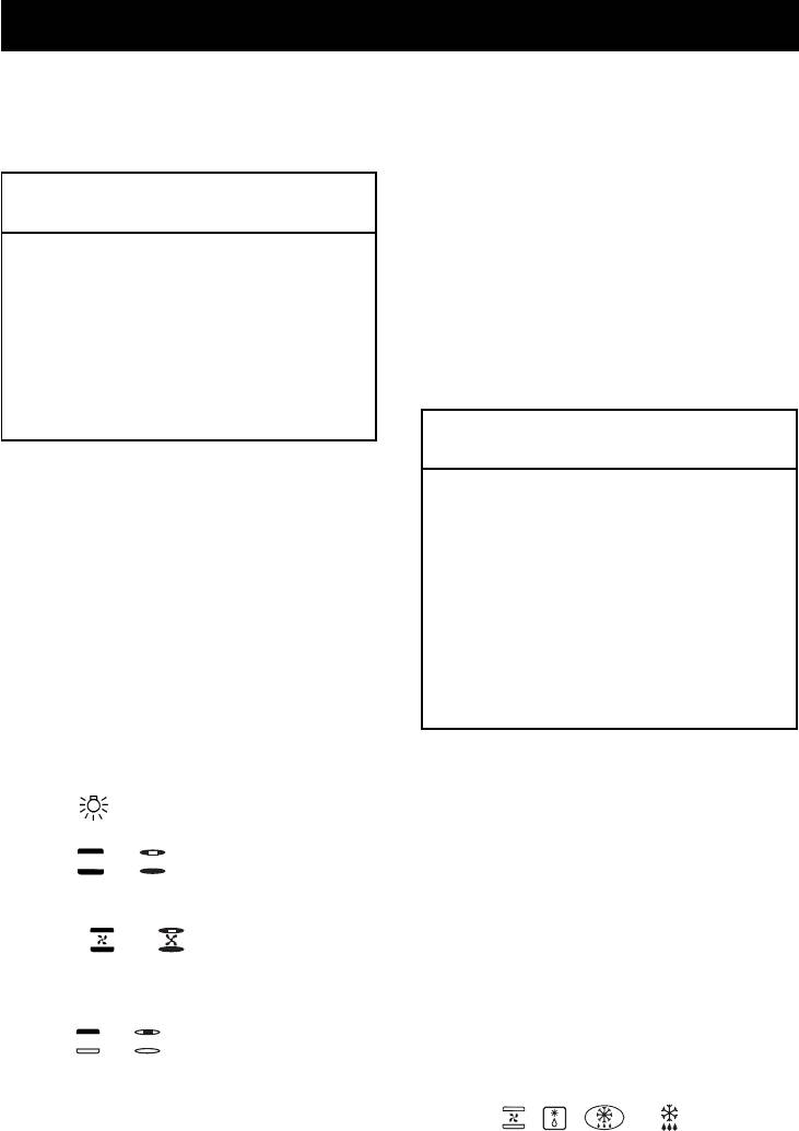
Position manette thermostat
- La grille du four sert pour supporter les plats
(Température en °C)
ou directement la viande à cuire.
- Ne pas utiliser la lèche-frite comme plat à
60
cuire, elle sert uniquement pour recueillir
80
le jus ou la graisse tombant des mets
100
pendant la cuisson avec le grilloir.
120
- Si on cuit simultanément sur deux gradins
150
il faut tenir compte que les temps peuvent
180
être différents.
200
220
Position manette thermostat
(Température en °C)
FOUR ELECTRIQUE MULTIFOUR
Grâce aux différents éléments chauffants,
50
commandés par un sélecteur et reglés par
80
un thermostat, le four offre différents modes
110
de cuisson, fondés sur 3 sources de chaleur:
130
a) Propagation forcée de la chaleur
150
(ventilation).
170
b) Propagation spontanée de chaleur
190
(convection ou four statique).
210
c) Rayons infra-rouges (grilloir).
230
Partant de la position 0 (éteint) et en tournant
250
la manette du sélecteur dans le sens des
aiguilles d’une montre, on assure
successivement les opérations suivantes:
FOUR ELECTRIQUE MULTIFONCTION
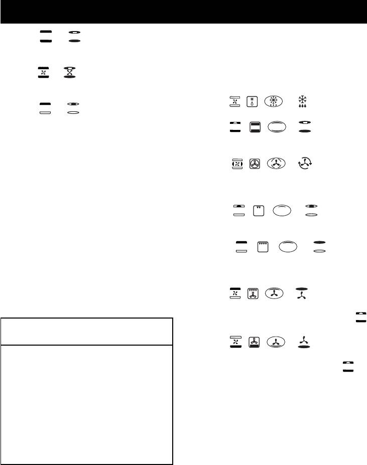
- repère : allumage de la lampe du four
Grâce aux différents éléments chauffants,
commandés par un sélecteur et reglés par
et du voyant rouge.
un thermostat, le four offre différents modes
- repère
ou : cuisson conventionelle
de cuisson, fondés sur 3 sources de chaleur:
four "statique", les températures du four se
a) Propagation forcée de la chaleur
réglent tournant la manette du thermostat.
(ventilation).
- repère
ou : cuisson avec four
b) Propagation spontanée de chaleur
"ventilé", sur un ou deux niveaux, les
(convection ou four statique).
températures du four se réglent tournant
c) Rayons infra-rouges (grilloir).
la manette du thermostat.
Partant de la position 0 (éteint) et en tournant
- repère
ou : allumage du grilloir (sur
la manette du sélecteur dans le sens des
le plafond du four), la manette du
aiguilles d’une montre, on assure
thermostat doit être en position de tempe-
successivement les opérations suivantes:
rature maximale.
- repère
, , ou : allumage de
Dans toutes les positions (excepté le 0) le
la lampe du four et du voyant rouge, mise
voyant rouge et la lampe du four s'allument.
24

FR
Pour l'utilisateur
en marche du ventilateur.
UTILISATION DU TOURNEBROCHE
- Placer la protection manette selon la figu-
- repère
, , ou : cuisson
re 13;
conventionelle four "statique", les
- allumer le brûleur de grilloir, ou mettre en
températures du four se réglent tournant
marche le grilloir électrique;
la manette du thermostat.
- enfiler la broche bien au centre du morceau
- repère , , ou : cuisson avec
à rôtir en la fixant par les deux fourchettes
four "ventilé", sur un ou deux niveaux, les
mobiles;
températures du four se réglent tournant
- pousser à fond la broche dans son
la manette du thermostat.
logement sur le moteur;
- repère
, , ou : allumage du
- dévisser la poignée de la broche;
grilloir (sur le plafond du four), la manette
- placer la lèche-frite sur le gradin inférieur
du thermostat doit être en position d'aper-
du four;
ture maximale.
- fermer doucement la porte du four en
l'adossant à la protection manettes;
- repère , , ou : cuisson à
- mettre en marche le moteur à l’aide de
rayons infra-rouges avec grilloir "renforcé"
l’interrupteur repéré avec le symbole.
pour grillades étendues, la manette du
- arroser la viande de temps en temps. Une
thermostat doit être en position de tempe-
fois la cuisson terminée, visser la poignée
rature maximale.
et enlever la broche.
- repère , , ou : cuisson rapi-
de avec four "ventilé", les températures du
Position manette thermostat
four corrispondent à celles du repère
(Température en °C)
dans le tableau.
- repère
, , ou : cuisson douce
avec four "ventilé", les températures du four
corrispondent à celles du repère
dans
60 50
80 80
le tableau.
110 110
Dans toutes les positions (excepté le 0) le
140 130
voyant rouge et la lampe du four s'allument.
170 150
REMARQUE: Le voyant jaune s’allume
200 170
lorsque le thermostat intervient.
220 190
Avant d'introduire les mets à cuire,
250 210
préchauffer le four pendant 10 minutes au
230
moins.
250
- La grille du four sert pour supporter les plats
ou directement la viande à cuire.
FOURS AVEC THERMOSTAT
- Ne pas utiliser la lèche-frite comme plat à
Si, au cours de la cuisson, on remarque une
cuire, elle sert uniquement pour recueillir
température anormale, consulter un
le jus ou la graisse tombant des mets
technicien pour un contrôle du thermostat.
pendant la cuisson avec le grilloir.
UTILISATION DE LA MINUTERIE (Fig. 14)
- Si la cuisson est effectuée avec un four
Programmer la durée de cuisson souhaitée
ventilé, il est possible de charger en même
en tournant la manette de la minuterie dans
temps les deux grilles. De toute façon si
le sens des aiguilles d'une montre. A la fin
les mets se diffèrent entre eux par quantité
du temps programmé un signal sonore se
ou nature, les temps de cuisson aussi
met en marche.
seront différents.
25

FR
Pour l'utilisateur
UTILISATION DU PROGRAMMATEUR DE
- si les robinets deviennent anormalement
FIN CUISSON MONOCOMMANDE (SANS
durs, contacter le S.A.V.;
HORLOGE) (fig. 15)
- les parties émaillées ou chromées se
Il permet de programmer la durée de cuisson.
nettoient avec de l’eau savonneuse tiède
Fonctionnement:
ou des détersifs non abrasifs. Pour les
- Positionner la manette sur le temps de
brûleurs supérieurs et les chapeaux de
cuisson souhaitée (120 minutes maxi pour
brûleurs on peut employer une brosse
four électrique; 100 minutes maxi pour four
métallique en cas de salissures importantes.
à gaz).
Essuyer soigneusement;
- Choisir la température en utilisant la manette
- ne pas utiliser de détersifs abrasifs pour
du thermostat et positionner la manette du
nettoyer les parties émaillées ou chromées;
sélecteur sur le type de cuisson choisi.
- lorsqu’on nettoie la table de cuisson, éviter
- Quand la manette du programmateur se
toute inondation. Faire attention pour que
positionnera sur le répère 0 la cuisson sera
l’eau ou autre n’entrent pas dans les trous
terminée. L’interruption de la cuisson est
de logement des brûleurs, ce qui pourrait
automatique.
être dangereux;
- Positionner de nouveau la manette du
- les bougies d’allumage électrique doivent
thermostat sur le répère .
tou-jours être propres et sèches; les
- Positionner aussi la manette du sélecteur
nettoyer après chaque utilisation et en cas
sur le répère 0.
de débordement;
N.B.: L’utilisation du four sans program-
- couvercles en verre: Ne pas les fermer tant
mation ne peut s’effectuer qu’en positionnant
que les brûleurs ou les plaques de la table
la manette du programmateur sur le répère
de cuisson sont chauds, parce qu'ils
(fonctionnement manuel).
peuvent s'ébrécher ou se casser;
- ne pas heurter les parties émaillées ou les
bougies d'allumage (si la cuisinière en est
COFFRE CHAUFFE-PLATS
équipée);
Pour ouvrir le coffre chauffe-plats, lever
- quand la cuisinière est éteinte, le robinet
l’abattant avec une main (voir fig. 16).
central (ou mural) du gaz doit être fermé.
Refermer en poussant l’abattant dans son
- ne soulever jamais la cuisinère par la
logement.
poignée de la porte de four.
CONSEILS ET AVERTISSEMENTS
Notre Société ne sera pas responsable pour
D’ORDRE GENERAL
les dommages causés aux personnes ou aux
- Avant toute intervention, à l’intérieur du four
choses qui sont provoqués par une
ou sur des pièces sous tension, il faut
installation incorrecte ou un mauvaise
débrancher la cuisinière;
utilisation de l’appareil.
- ne pas utiliser le coffre chauffe-plats pour
En cas d’anomalies et surtout s’il y a des
y mettre des liquides inflammables ou
fuites de gaz ou de courant, consulter
objets qui craignent la chaleur, tel que bois,
immédiatement un technicien.
papier, bombes à pression, allumettes, etc.;
- contrôler souvent le tube de raccordement
en caoutchouc pour qu’il soit loin de parois
chaudes, qu’il ne soit pas replié et qu'il soit
toujours en bonnes conditions. Le tuyau
doit être remplacé au plus tard avant la date
indiquée et fixé aux extrémités par des
colliers de serrage normalisés;
26

GB
Index
Introduction
Technical data and
- Thank you for choosing one of our quality
products, capable of giving you the very
specifications.........................28
best service. To make full use of its perfor-
Installation ..................... 29 - 32
mance features, read the parts of this
Ventilation................................ 29
manual which refer to your appliance
Positioning............................... 29
carefully. The Manufacturer declines all
Gas connection ....................... 29
responsibility for injury or damage
caused by poor installation or improper
Adapting to different types
use of the appliance.
of gas....................................... 30
- To ensure its appliances are always at the
Replacing the injectors............ 30
state of the art, and/or to allow constant
Regulating the air .................... 30
improvement in quality, the manufacturer
reserves the right to make modifications
Minimum setting ...................... 30
without notice, although without creating
Electrical connection ............... 31
difficulties for users.
Electric ignition ........................ 31
- When ordering spare parts, inform your
Safety device........................... 31
dealer of the model number and serial
For the user.................. 32 - 38
number punched on your appliance’s
nameplate, visible inside the warming
Ventilation................................ 32
compartment or on the back of the cooker.
Igniting the burners................. 32
- APPLIANCE COMPLYING WITH THE
Igniting the gas oven .............. 32
FOLLOWING DIRECTIVES:
Igniting the gas grill ................. 33
- EEC 90/396
Safety device........................... 33
- EEC 73/23 and 93/88
- EEC 89/336 (radio-frequency inter-
Electrical switch-on.................. 33
ference)
Using the gas hob ................... 33
- EEC 89/109 (contact with foods)
Using the electric hot-plates.... 33
Using the gas oven.................. 34
FOREWORD
Using the gas or electric grill ... 34
- Refer only to the headings and sections
covering accessories actually installed on
Using the static electric oven... 35
your cooker.
Using the electric fan oven...... 35
Using the multifunction electric
oven with 4 cooking programs. 35
Using the multi-function
electric oven ............................ 36
Using the rotisserie.................. 37
Oven with thermostat .............. 37
Using the minute minder ......... 37
Using the single-control
cooking timer........................... 37
Warming compartment ............ 37
Advice and precautions........... 37
Figures ......................... 78 - 80
27

GB
Technical data and specifications
TOTAL ELECTRIC OVEN POWER
Nominal external Cookers Cookers
static oven 2.21 kW
dimensions 50x50 54x54
Height at hob cm 85,0 cm 85,0
fan oven 2.0 kW
Height with lid raised cm 133,0 cm 137,0
multi-oven 2.21 kW
Height w. glass lid raised cm 133,3 cm 137,5
multifunction oven 2.7 kW
Depth with door closed cm 50,0 cm 54,0
Depth with door open cm 96,0 cm 100,0
Cat.: see nameplate on cover; Class 1 or 2.1
Width cm 50,0 cm 54,0
Type “X” cookers
Usable Oven Fan
dimensions oven
EQUIPMENT
Width cm. 39,5 cm. 39,5
All models are equipped with safety device
Depth cm. 42,0 cm. 40,0
for oven and grill burners.
Height cm. 31,5 cm. 31,5
Depending on the models, cooker may also
Volume l. 52,0 l. 50,0
have:
- Safety device for one or more hob burners
- Electric ignition on top burners
GAS BURNERS (injectors and flow-rates)
- Electric ignition on oven and grill burners
Gas Burner Injector low nominal
- Oven thermostat (or tap)
flow-rate flow-rate
- Electric oven lighting
(kW) (kW)
G20 auxiliary 70 0,40 0,90
- Rotisserie
20 semi-rapid 99 0,40 1,85
- Grill burner
mbar rapid 126 0,85 3,00
- Mechanical timer
oven 130 1,00* 3,00
- Single-control end of cooking timer
grill 110 2,00
- One or more electric hotplates
G30 auxiliary 48 0,40 0,90
28-30 semi-rapid 68 0,40 1,85
For the LAYOUT OF HOB BURNERS see
mbar rapid 86 0,85 3,00
G31 oven 86 1,00* 3,00
the models illustrated in figure 1 at the back
37 grill 70 2,00
of this manual.
mbar
* For thermostat. In case of oven with tap: 1.3 kW
For the ELECTRIC WIRING DIAGRAM see
figure 2 at the back of this manual.
ELECTRIC HOTPLATES
The electrical power is stated on the name-
ø 145 1,0 kW - Normal hotplate
plate visible inside the warming compartment
1,5 kW - Rapid hotplate
(if present) or on the back of the cooker.
A copy of the nameplate is glued to the cover
ø 180 1,5 kW - Normal hotplate
of this manual (for gas or gas-electric prod-
2,0 kW - Rapid hotplate
ucts only).
HEATING ELEMENT POWERS
bottom element 1.5 kW
top element 0.7 kW
oven circular element 2.0 kW
grill 2.0 kW
fan 25 W
oven light 15 W
28

GB
Installation
INSTALLATION
about 50°C.
The appliance must be installed by qualified
- Rigid connection (see fig. 3 A + B)
staff working in accordance with the regula-
The connection to the mains gas supply
tions in force.
may be made using a rigid metal pipe or
Before installing, ensure that the appliance
with a metal hose. Remove the hose
is correctly preset for the local distribution
connector (if already fitted) and screw the
conditions (gas type and pressure).
rigid union onto the threaded connection
The presettings of this appliance are indi-
of the gas train (see fig. 3A). The union for
cated on the nameplate shown on the cover.
rigid connection may already be fitted on
This appliance is not connected to a flue gas
the gas train, or may be amongst the cooker
extractor device. It must be installed and
accessories. Otherwise, it can be obtained
connected in accordance with the regulations
from your dealer.
in force.
If national regulations permit, a metal hose
This appliance may only be installed and may
complying with the national standards can
only operate in rooms permanently ventilated
be screwed directly onto the threaded
in accordance with national regulations in
connection of the gas train, fitting a seal
force.
(see fig. 3B). However, users are strongly
recommended always to fit the rigid union.
VENTILATION
- Connection using a rubber hose (see fig.
The rooms in which gas appliances are in-
3C). (For butane/propane gas only).
stalled must be well ventilated in order to al-
Connect a rubber hose carrying the
low correct gas combustion and ventilation.
conformity mark currently in force to the hose
The air flow necessary for combustion is at
connector. The hose must be replaced at
3
least 2 m
/h for each kW of rated power.
the date indicated at the latest, and must
be secured at both ends using standard
POSITIONING
hose clamps. It must be absolutely
Remove the packaging accessories, includ-
accessible to allow its condition to be
ing the films covering the chrome-plated and
checked along its entire length.
stainless steel parts, from the cooker.
CAUTION:
Position the cooker in a dry, convenient and
- Use of the hose connector is only
draft-free place. Keep at an appropriate dis-
permitted for free-standing installation.
tance from walls which may be damaged by
If the appliance is installed between two
heat (wood, linoleum, paper, etc.).
class 2 st. 2-1 unions, the rigid union is
The cooker may be free-standing (class 1)
the only form of connection permitted.
or between two units (in class 2 st 2-1) the
IMPORTANT:
sides of which must withstand a temperatu-
- After installation, check that the
re of 100°C and which must not be higher
connections are airtight.
than the working table.
- For operation with butane/propane, check
that the gas pressure is as indicated on the
CONNECTING TO THE GAS SUPPLY
nameplate.
Before connecting the cooker, check that it
- Use only standard rubber hoses. For LPG,
is preset for the gas to be used. Otherwise,
use a hose which complies with the national
make the conversion as described in the
regulations in force.
section headed “Adapting to different gas
- Avoid sharp bends in the pipe and keep it
types”. The connection is on the right; if the
well way from hot surfaces.
pipe has to pass behind the cooker, it must
References to the regulations covering the
be kept low down where the temperature is
gas connection to the appliance: ISO 7-1.
29

GB
Installation
ADAPTING TO DIFFERENT TYPES OF
REGULATING THE BURNER AIR
GAS
Refer to the table below (indicative values)
If the cooker is not already preset to operate
for regulation of the gap H in mm (fig. 4 for
with the type of gas available, it must be con-
the hob, fig. 6 for the grill).
verted. Proceed as follows:
Burner G20 20mbar G30 28-30mbar
- Replace the injectors (see table on page
G31 37mbar
24);
Auxiliary 3 4
- regulate the primary air flow;
Semi-rapid 3 3
- regulate the minimum settings.
Rapid 4 6
N.B.: every time you change the type of gas,
Oven - -
indicate the new type of gas on the serial
Grill 3 8
number label.
Check operation of the burner:
REPLACING THE HOB BURNER INJEC-
- Ignite the burner at maximum flame;
TORS (fig. 4)
- the tongue of the flame must be clear and
- Remove the lid of the cooker by lifting it off
with no yellow tip, and must adhere closely
its supports;
to the burner. If too much air is supplied,
- remove the grids, burner caps and burners,
the flame detaches from the burner and
lifting them off;
may be dangerous. If the air supply is in-
- unscrew the 2 screws (above) or nuts
sufficient, the flame has a yellow tip and
(below) at the back which secure the work
soot may form.
top, and pull it out forward.
- remove the mixer pipes and replace the
SETTING HOB BURNER MINIMUM LEV-
injectors using a 7 mm socket wrench.
ELS
If the cooker is to work on bottled gas (bu-
REPLACING THE OVEN BURNER INJEC-
tane/propane), the tap by-pass must be
TOR (Fig. 5)
screwed right down.
- Loosen the screw which secures the bottom
The cooker may be equipped with type A
of the oven;
taps, with by-pass inside (accessed by in-
- remove the oven bottom (pulling it forward);
serting a small screwdriver into the rod) or
- remove the oven burner, after taking out
type B taps, with by-pass on the outside on
the screw which secures it;
the right (accessed directly). See figure 7.
- replace the injector using a 7 mm socket
If the cooker is to work on natural gas, pro-
wrench.
ceed as follows for both types of tap:
- Ignite the burner at maximum flame;
REPLACING THE GRILL BURNER INJEC-
- pull off the knob, without using a lever
TOR (Fig. 6)
against the control panel, which might be
- Remove the burner after taking out the two
damaged;
screws which secure it;
- access the by-pass with a small screwdriver
- replace the injector using a 7 mm socket
and back off by about 3 turns (turning the
wrench.
screwdriver anti-clockwise);
- turn the tap rod anti-clockwise again until it
IMPORTANT:
stops: the burner will be at maximum flame;
- Never over-tighten the injectors;
- screw the by-pass slowly back in, without
- after replacing, check that all the injectors
pushing the screw-driver, until the flame has
are airtight.
apparently shrunk to 1/4 of the maximum
size, checking that it is sufficiently stable
30

GB
Installation
even in quite strong draughts.
- the lead must never touch hot surfaces over
about 75 degrees C;
SETTING OVEN BURNER MINIMUM LEV-
- replacement leads must be of type H05RR-
ELS
F or H05V2V2-F of suitable size (see dia-
If the cooker is to work on bottled gas (bu-
grams in fig. 2).
tane/propane), the thermostat by-pass must
- if the appliance is supplied without lead,
be screwed right down.
using type H05RR-F or H05V2V2-F cable
If the cooker is to work on natural gas, pro-
of suitable size (see diagrams in fig. 2).
ceed as follows:
IMPORTANT: the manufacturer declines all
- Remove the oven bottom (loosen the screw
liability for damage due to failure to comply
to remove the bottom);
with the regulations and standards in force.
- ignite the oven burner, turning the knob
Check that the appliance is correctly con-
pointer to the maximum setting;
nected to the earth (see diagrams in fig. 2 at
- shut the oven door;
the back of the manual).
- access the thermostat or tap by-pass (see
fig. 8);
FOR COOKERS WITH ELECTRIC IGNI-
- back off the thermostat by-pass by about 3
TION
turns;
The correct gaps between the electrode and
- after 5 or 6 minutes, turn the knob pointer
the burner are shown in figures 4, 5 and 6.
to the minimum setting;
If no spark is generated, do not keep on try-
- slowly re-tighten the by-pass, watching the
ing as this might damage the generator.
flame decrease in size through the window
Possible causes of malfunctions:
in the closed oven door until the tongue of
- spark plug damp, dirty or broken;
the flame is about 4 mm long. Never keep
- electrode-burner gap not correct;
the flame too low. It must be stable even
- spark plug wire broken or without sheath-
when the oven door is opened or closed
ing;
quickly;
- spark discharging to earth (to other parts
- turn off the burner and replace the oven
of the cooker);
bottom.
- generator or microswitch damaged;
- air has built up in the pipes (particularly if
CONNECTING TO THE ELECTRICAL
the cooker has been out of use for a long
MAINS
time);
Before making the connection, check that:
- air-gas mixture incorrect (poor fuel setting).
- the mains voltage is as indicated on the
nameplate;
THE SAFETY DEVICE
- the earth connection is in good working or-
The correct gap between the end of the ther-
der.
mocouple sensor and the burner is shown in
If the socket is not easily accessible, the in-
figures 4, 5 and 6.
stallation engineer must provide a switch with
To check that the valve is working properly,
a contact breaking gap of 3 mm or more.
proceed as follows:
If the appliance power lead is not fitted with
- ignite the burner and leave it to work for
a plug, use an approved standard type, re-
about 3 minutes;
membering that:
- turn off the burner by returning the knob to
- the green-yellow wire must be used for the
off position ( );
earth connection;
- after 90 seconds for hob burners, 60 sec-
- the blue wire is the neutral;
onds for oven and grill burners, turn the
- the brown wire is live;
knob pointer to the "on" position;
31
GB
Installation
For the user
- release the knob in this position and move
HOW TO USE THE COOKER
a burning match towards the burner; IT
MUST NOT IGNITE.
VENTILATION
Time needed to excite the magnet during
All gas cooking appliances produce heat and
ignition: 10 seconds approx.
moisture in the rooms where they are
Automatic tripping time, after flame has been
installed. Take care to ensure that the kitchen
turned off: not more than 90 seconds for hob
is well ventilated; keep the ventilation
burners; not more than 60 seconds for oven
openings unobstructed or install an extractor
and grill burners.
hood with fan.
In case of intensive or prolonged use,
IMPORTANT
additional ventilation may be required; open
- Before doing any work inside the cooker,
a window, or increase the extractor fan power.
disconnect the mains plug and shut the gas
tap.
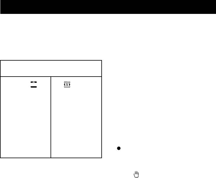
IGNITING THE HOB BURNERS
- Never use matches to check the gas cir-
- Press the knob and turn it anti-clockwise
cuit for leaks. If a specific control device is
until it reaches the
symbol on the control
not available, foam or very soapy water can
panel (maximum flame position);
be used.
- at the same time, move a burning match
- When re-closing the hob, check that the
towards the burner head;
electrical wires of the spark plugs (if
- to reduce the flame, turn the knob further
present) are not close to the injectors, so
in the same direction until its pointer is
that they cannot run across them.
against the
symbol (minimum flame po-
sition).
FOR HOB BURNERS EQUIPPED WITH
SAFETY DEVICE
- Press the knob and turn it anti-clockwise
until it reaches the
symbol on the control
panel (maximum flame position);
- move a burning match towards the burner,
keeping the knob pressed right dow for
about 10 seconds;
- then release the knob and check that the
burner remains on. Otherwise, repeat the
operation.
IGNITING THE OVEN BURNER
- Open the oven door;
- press the knob and turn it anti-clockwise to
the maximum flame position;
- move a burning match towards the hole in
the centre of the oven bottom and press
the knob right down (see fig. 9);
- check that the burner has ignited, looking
through the hole in the centre of the bot-
tom, keeping the knob pressed all the time;
32
GB
For the user
- after about 10 seconds, release the knob
these 10 seconds, stop using the device,
and check that the burner remains on. Oth-
leave the door open and wait one minute
erwise, repeat the operation.
before trying again to ignite the burner. If
the ignition device malfunctions again, light
IGNITING THE GRILL BURNER (GAS
the burner with a match and call the after-
GRILLS)
sales service.
- Fit the control knob guard as shown in fig.
IMPORTANT
12;
- Difficulty in igniting burners is normal if the
- press the oven knob and turn it to the right
cooker has been out of use for some time.
until it reaches the stop;
The air accumulated in the pipes will be
- move a burning match towards the perfo-
expelled in a few seconds;
rated burner pipe and press the knob right
- Never allow too much unburnt gas to flow
down (see fig. 10);
from the burners. If ignition is not achieved
- check that the burner has ignited, keeping
within a relatively short time, repeat the pro-
the knob pressed down;
cedure after returning the knob to the off
- after about 10 seconds, release the knob
position ( );
and check that the burner remains on. Oth-
- when the oven and grill are lit for the first
erwise, repeat the operation.
time, a smell may be noticed and smoke
may come out of the oven. This is because
SAFETY DEVICE
of the surface treatment and oily residues
Burners equipped with this device have the
on the burners.
advantage that they are protected if they
accidentally go out. If this occurs, the supply
HOW TO USE THE HOB BURNERS
of gas to the burner concerned is automati-
Use pans of diameter suitable for the burner
cally cut off, preventing the hazards deriving
type. The flames must not project beyond
from a leak of unburnt gas. The gas supply
the base of the pan. Recommended sizes:
must be cut off within no more than 60 sec-
- for auxiliary burners = pans of at least 8 cm
onds for the oven and grill burners or 90 sec-
- for semi-rapid burners = pans of at least
onds for the hob burners.
14 cm
- for rapid burners = pans of at least 22 cm.
FOR COOKERS WITH ELECTRIC IGNI-
N.B.: Never keep the knob at settings be-
TION
tween the maximum flame symbol
and the
All the above applies, except that the match
off position
( ).
is no longer required; a spark is obtained by
pressing the button on the control panel once
FOR COOKERS EQUIPPED WITH ELEC-
or more, or by pressing the knob of the burner
TRIC HOTPLATES
to be ignited.
The different heat settings are obtained as
If electronic ignition is difficult with some
follows:
types of gas, set the knob on the low (small
- 1 = minimum setting for all hotplates;
flame) setting.
- 6 = maximum setting for normal and rapid
- For cookers with electric ignition of the
hotplates (with red disc);
oven and grill burners, ensure the oven
- 0 = off.
door is completely open when these
Pans must never be smaller in diameter than
burners are ignited;
the hotplates and their bottoms must be as
- Do not operate the ignition device for more
flat as possible (see fig. 11).
than 10 seconds when igniting the oven and
IMPORTANT:
grill burners. If the burner has not lit after
- Never leave hotplates on without pans,
33
GB
For the user
except when first used; leave for about 10
HOW TO USE THE GAS OR ELECTRIC
minutes to dry oil or moisture residues;
GRILL
- if the hotplate is to be out of use for a long time,
- fit the knob guard (see fig. 12);
apply a little grease to its painted surface;
- ignite the burner and wait a few minutes to
- do not allow spills to burn onto the hotplate,
allow it to warm up, or switch on the heat-
requiring the use of abrasive cleaners.
ing element;
- place the foods on the chrome-plated shelf;
HOW TO USE THE GAS OVEN
- insert on the highest runner;
- After igniting the burner, leave the oven to
- insert the drip tray on the bottom runner;
heat up for about 10 minutes;
- gently close the oven door, resting it against
- place the food for cooking in an ordinary oven
the knob guard;
dish and place it on the chrome-plated shelf;
- after a few minutes, turn the food to expose
- place the food in the oven, using the shelf
the other side to the infrared radiation (the
on the third pair of runners whenever pos-
cooking time depends on the type of food
sible, and turn the knob pointer to the de-
and personal taste).
sired setting;
N.B.: the first time the grill is used smoke
- cooking can be observed through the win-
will come out of the oven. Before inserting
dow in the door with the oven light on. This
foods for cooking, wait until any oil residues
will avoid opening and closing the door fre-
on the burner have completely burnt away.
quently, unless oil or fat has to be added to
The grill must only be used at its full rated heat.
the dish.
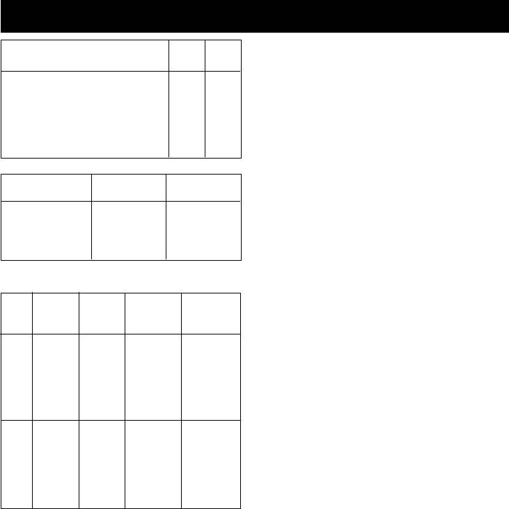
IMPORTANT: accessible parts may be hot
when the grill is in use! Keep children well
Thermostat Temperature
away.
knob setting in°C
The grill element in the top of the oven is
1 150
switched on by turning the thermostat knob
2 170
clockwise to the grill symbol on the control
3 190
panel.
4 210
The red light will come on to show the ele-
5 230
ment is in operation.
6 250
The table below will serve as a guide; bear-
7 270
ing in mind that cooking times and tempera-
tures may vary depending on the type and
IMPORTANT: never place foods directly on
amount of foods cooked and personal taste.
the drip tray for cooking; it is there only to
collect any drips of fat during grilling.
Food to be Time (minutes)
N.B.: For cookers without thermostat:
grilled 1st side 2nd side
- with the knob on the maximum setting
=
270 degrees C
Thin pieces of meat 6 4
- with the knob on the minimum setting
=
Fairly thick pieces of
150 degrees C
meat 8 5
- All other temperatures between 150 and
Thin fish or fish
270 degrees C are obtained approximately
without scale 10 8
by positioning the knob between the maxi-
Fairly thick fish 15 12
mum and minimum settings.
Sausages 12 10
Never leave the knob in positions between
Toasted sandwiches 5 2
Small poultry 20 15
the maximum symbol
and the off setting
(
).
34
GB
For the user
STATIC ELECTRIC OVEN
There is a single control knob for the oven
- The oven shelf is designed to take normal
or grill.
oven dishes for cooking sweets or roasts,
Starting from the 0 (off) position, the knob
or is used without a pan for cooking foods
can be turned clockwise to the following set-
under the grill.
tings:
- The drip tray is only there to collect any juice
-
symbol: oven lamp on (it will re-
from foods and must never be used as a
main on even if the knob pointer is turned
cooking surface.
to the other settings) and operation of the
There is a single control knob for the oven
fan.
or grill.
- Setting from 60 to 220 degrees C: oven
Starting from the 0 (off) position, the knob
heat settings, with thermostat control.
can be turned clockwise to the following set-
- symbol: grill on (in roof of oven)
tings:
Turn the knob anti-clockwise to return to the
- symbol: oven lamp on (it will remain on
0 (off) position.
even if the knob pointer is turned to the
N.B. - The yellow light switches on and off
other settings).
as the thermostat is tripped.
- Setting from 1 to 8 (or from 60 to 250 de-
Before placing food inside, allow the oven to
grees C): oven heat settings, with thermo-
heat up for at least 10 minutes.
stat control.
-
symbol: grill on (in roof of oven)
Thermostat knob setting
-
symbol: rotisserie start with grill on.
Temperature in°C
Turn the knob anti-clockwise to return to the
0 (off) position.
60
N.B. - The yellow light switches on and off
80
as the thermostat is tripped.
100
Before placing food inside, allow the oven to
120
heat up for at least 10 minutes.
150
180
Thermostat Temperature
200
knob setting in°C
220
1 60
2 80
MULTIFUNCTION ELECTRIC OVEN WITH
3 110
4 COOKING PROGRAMS
4 140
With different heating elements controlled
5 170
using a selector switch and regulated by a
6 200
thermostat, this oven offers various cooking
7 220
programs. There are three principle sources
8 250
of heat:
a) Forced heat diffusion (fan oven)
ELECTRIC FAN OVEN
b) Spontaneous heat diffusion (static oven)
- The oven shelf is designed to take normal
c) Infra-red rays (grill)
oven dishes for cooking sweets or roasts,
Starting from the position 0 (off) the selector
or is used without a pan for cooking foods
knob can be turned clockwise to the follow-
under the grill.
ing positions:
- The drip tray is only there to collect any juice
- symbol
: oven light and red warning
from foods and must never be used as a
light on
cooking surface.
35
GB
For the user
a) Forced heat diffusion (fan oven)
- symbol or : conventional "static"
b) Spontaneous heat diffusion (static oven)
oven cooking, the oven temperature is con-
c) Infra-red rays (grill)
trolled using the thermostat knob.
Starting from the position 0 (off) the selector
- symbol
or : cooking with fan oven,
knob can be turned clockwise to the follow-
on one or two levels, the oven temperature
ing positions:
is controlled using the thermostat knob.
- symbol , , or : oven light and
- symbol
or : grill on (on oven top
red warning light on, operation of fan.
element), the thermostat knob must be set
- symbol
, , or : conventional
at maximum temperature.
"static" oven cooking, the oven tempera-
In all positions except zero (0) the red warn-
ture is controlled using the thermostat knob.
ing light and the oven light are on.
NOTE: The yellow warning light comes on
- symbol , , or : cooking with
according to thermostat variations. Before
fan oven, on one or two levels, the oven
putting food in to be cooked, the oven should
temperature is controlled using the ther-
be pre-heated for at least 10 minutes.
mostat knob.
- The oven shelf is designed to take normal
- symbol
, , or : grill on (on
oven dishes for cooking sweets or roasts,
oven top element), the thermostat knob
or is used without a pan for cooking foods
must be set at the maximum temperature.
under the grill.
- symbol , , or : infra-red
- The drip tray is only there to collect any juice
cooking with fast grill, advised for long
from foods and must never be used as a
grilling: the thermostat knob should be set
cooking surface.
at the maximum temperature.
- Remember that cooking times may vary if
food is cooked on two shelves at the same
- symbol , , or : quick cooking
time.
using the fan oven, the oven temperatures
correspond to those under the symbol
Thermostat knob setting
in the table.
Temperature in°C
- symbol
, , or : slow cooking
using fan oven, the oven temperatures cor-
50
respond to those under the symbol
in
80
the table.
110
In all positions except zero (0) the red warn-
130
ing light and the oven light are on.
150
NOTE: The yellow warning light comes on
170
according to thermostat variations. Before
190
putting food in to be cooked, the oven should
210
be pre-heated for at least 10 minutes.
230
- The oven shelf is designed to take normal
250
oven dishes for cooking sweets or roasts,
or is used without a pan for cooking foods
MULTI-FUNCTION ELECTRIC OVEN
under the grill.
With different heating elements controlled
- The drip tray is only there to collect any juice
using a selector switch and regulated by a
from foods and must never be used as a
thermostat, this oven offers various cooking
cooking surface.
methods. There are three principle sources
- Remember that cooking times may vary if
of heat:
36
GB
For the user
food is cooked on two shelves at the same
HOW TO USE THE MINUTE MINDER (Fig. 14)
time.
Set the cooking time considered necessary
The table below will serve as a guide, bear-
by turning the timer knob clockwise. An alarm
ing in mind that cooking times and tempera-
will sound at the end of the preset time.
tures may vary depending on the type and
amount of foods cooked and personal taste.
USE OF SINGLE-CONTROL END OF COOK-
ING TIMER (WITHOUT CLOCK) (fig. 15)
Thermostat knob setting
This allows the cooking time to be pro-
Temperature in°C
grammed.
Operation:
- Move the knob to the desired cooking time
(120 mins max. for the electric oven; 100
60 50
mins max. for the gas oven).
80 80
- Choose the temperature using the thermo-
110 110
stat knob and move the selector knob to
140 130
the required cooking method.
170 150
- When the programming knob is at the 0
200 170
position the oven will switch itself off. This
220 190
is automatic.
250 210
- Move the thermostat knob back to symbol
230
.
250
- Move the selector knob to symbol 0.
N.B. If the timer is not used, the oven pro-
HOW TO USE THE ROTISSERIE
gramming knob is to be set to the manual
- fit the control knob guard as shown in fig-
position .
ure 13.
- ignite the grill burner, or switch on the grill
WARMING COMPARTMENT
element;
To open the warming compartment, open the
- impale the meat for cooking on the spit and
flap door with one hand (see figure 15).
fix it in the centre of the two forks;
To close the warming compartment, simply
- insert the end of the spit into the motor drive
press the flap door back into place.
socket;
- remove the handle from the spit;
GENERAL PRECAUTIONS
- place the drip tray on the bottom runner of
- Always disconnect the power supply before
the oven;
any work inside the oven or where live parts
- gently close the oven door, resting it against
may be accessed.
the knob guard;
- Never use the warming compartment for
- start the rotisserie motor by pressing the
storing inflammable liquids or items which
switch on the symbol.
do not withstand heat, such as wood, pa-
- baste the meat from time to time. When
per, aerosol cans, matches, etc.
cooked, screw the handle onto the spit and
- Make frequent checks on the rubber con-
remove from the motor drive socket.
nection hose, ensuring that it is well away
from hot surfaces, that there are no sharp
OVENS WITH THERMOSTAT
bends or kinks, and that it is in good condi-
If cooking temperatures are not as set, call
tion. The hose must be replaced at the lat-
in an engineer to check the thermostat.
est at the indicated date and must be se-
37

GB
For the user
cured at both ends using a standard hose
clamp.
- If taps become stiff to operate over time,
contact the After-Sales service.
- Wash enamelled or chrome-plated parts
with soapy lukewarm water or non-abrasive
detergents. A metal brush may be used to
remove deposits from hob burners and
flame caps. Dry thoroughly.
- Never use abrasives to clean enamelled or
chrome-plated parts.
- Do not use too much water when washing
the hob. Take care that no water or other
substances enter the burner housing holes,
as this may be dangerous.
- The spark plugs for electric ignition must
be kept clean and dry; always check after
use, particularly if there have been drips or
overflows from pans.
- Never close glass lids until the hob burn-
ers or hotplates have cooled completely; it
might shatter or crack.
- Never knock enamelled parts or ignition
spark plugs (where present).
- The main or wall gas tap should be turned
off when the cooker is not in use.
- Never lift the cooker by taking hold of the
oven door handle.
No liability is accepted for injury or damage
caused by poor installation or improper use
of the cooker.
In case of malfunctions, particularly gas
leaks or short-circuits, contact your en-
gineer without delay.
38

RU
Soder'anieSoder'anie
Soder'anie
Soder'anieSoder'anie
Vstuplenie
VstuplenieVstuplenie
VstuplenieVstuplenie
Texniheskie dannye i
- Nawa firma blagodarit Vas za vybor i
pokupku odnogo iz nawix
xarakteristiki .................................... 40
vysokokahestvennyx izdelij. My gorqho
Ustanovka ...................................... 41 - 44
nadeemsq, hto v Vawix rukax nawi plity
Ventilqciq pome]eniq .......................... 41
budut funkcionirovat; s maksimal;noj
Razme]enie ................................................. 41
otdahej i nailuhwimi rezul;tatami,
Podkl[henie k gazoraspredelitel;noj
opravdyvaq vse Vawi o'idaniq. S `toj
seti ............................................................... 41
cel;[ predlagaem Vam vnimatel;no
Nastrojka na
prohitat; nastoq]ee rukovodstvo i
razlihnye tipy gaza ................................ 42
Zamena 'iklerov ....................................... 42
prider'ivat;sq tex ego ukazanij, gde
Regulirovka podahi vozduxa ................ 42
reh; idet o priborax i sistemax,
Regulirovka
kotorymi osna]ena Vawa plita.
Fabrika
FabrikaFabrika
FabrikaFabrika
minimal;nogo plameni .......................... 42
- izgotovitel; snimaet s sebq vsqku[- izgotovitel; snimaet s sebq vsqku[
- izgotovitel; snimaet s sebq vsqku[- izgotovitel; snimaet s sebq vsqku[
- izgotovitel; snimaet s sebq vsqku[
Podkl[henie k `lektroseti ................... 43
otvetstvennost; za povre'deniq,
otvetstvennost; za povre'deniq,otvetstvennost; za povre'deniq,
otvetstvennost; za povre'deniq,otvetstvennost; za povre'deniq,
~lektriheskoe za'iganie ....................... 44
neispravnosti i neshastnye sluhai,
neispravnosti i neshastnye sluhai,neispravnosti i neshastnye sluhai,
neispravnosti i neshastnye sluhai,neispravnosti i neshastnye sluhai,
Predoxranitel;noe gazokontrol;noe
vyzvannye nesobl[deniem rekomendacij
vyzvannye nesobl[deniem rekomendacijvyzvannye nesobl[deniem rekomendacij
vyzvannye nesobl[deniem rekomendacijvyzvannye nesobl[deniem rekomendacij
ustrojstvo .................................................. 44
po ustanovke i `kspluatacii plity.po ustanovke i `kspluatacii plity.
po ustanovke i `kspluatacii plity.po ustanovke i `kspluatacii plity.
po ustanovke i `kspluatacii plity.
Informaciq dlq
- Dlq togo, htoby vypuskat; plity v
potrebitelej ............................... 45 - 52
sootvetstvii s sovremennymi
Ventilqciq pome]eniq .......................... 45
texnologiheskimi reweniqmi i#ili dlq
Za'iganie gorelok ................................... 45
postoqnnogo povyweniq kahestva nawix
Vkl[henie gazovoj duxovki .................. 45
izdelij, fabrika ostavlqet za soboj
Vkl[henie gazovogo grilq ..................... 45
pravo vneseniq kakix-libo izmenenij
Predoxranitel;noe
da'e bez predvaritel;nogo
ustrojstvo gazokontrolq ....................... 45
predupre'deniq, hto, odnako, ne
~lektriheskoe za'iganie ....................... 46
vyzyvaet problem ili zatrudnenij pri
Ispol;zovanie gazovyx gorelok
`kspluatacii.
rabohej poverxnosti plity ................. 46
- Esli vozniknet neobxodimost; zakaza
Ispol;zovanie
zaphastej, nado sdelat; zapros Vawemu
`lektriheskix konforok ........................ 46
prodavcu, gde sleduet ukazat; nomer
Ispol;zovanie gazovoj duxovki .......... 47
modeli i nomer serii plity,
Ispol;zovanie gazovogo
^prowtampovannye na fabrihnoj
ili `lektriheskogo grilq ..................... 47
opoznavatel;noj tablihke. ~ta tablihka
Ispol;zovanie konvekcionnoj
mo'et byt; raspolo'ena vnutri
`lektriheskoj duxovki ........................... 48
otdeleniq razogreva tarelok (esli est;)
Ispol;zovanie `lektriheskoj
ili na zadnej storone plity.
duxovki s sistemoj ventilqcii .......... 48
- Plita sootvetstvuet normativam%
Ispol;zovanie `lektriheskoj
-CEE 90/396
kombinirovannoj
duxovki .................... 49
-CEE 73/23 i 93/68
Ispol;zovanie `lektriheskoj
-CEE 89/336 (po urovn[ radiopomex)
mnogofunkcional;noj
duxovki ........... 49
-CEE 89/109 (kontaktirovanie s
Ispol;zovanie vertela ........................... 50
pi]evymi produktami)
Duxovki s termoregulqtorom ............... 51
Ispol;zovanie tajmera .......................... 51
POQSNENIE
Ispol;zovanie programmiru[]ego
- V nastoq]em rukovodstve predstavlq[t
ustrojstva bez hasov ............................... 51
interes tol;ko te paragrafy ili
Otdelenie razogreva tarelok ............... 51
razdely, gde govorit;sq o priborax,
Rekomendacii po
kotorymi osna]ena Vawa plita.
texnike bezopasnosti .............................. 51
Risunki ......................................... 93 - 95
39
RU
Texniheskie dannye i xarakteristikiTexniheskie dannye i xarakteristiki
Texniheskie dannye i xarakteristikiTexniheskie dannye i xarakteristiki
Texniheskie dannye i xarakteristiki
Nomin. naru'n. razmery Nomin. naru'n. razmery
Nomin. naru'n. razmery Nomin. naru'n. razmery
Nomin. naru'n. razmery
Plity
PlityPlity
PlityPlity
PlityPlity
PlityPlity
Plity
POLNAQ MO}NOST: ~LEKTRIHESKOJ
50x5050x50
50x5050x50
50x50
54x54
54x5454x54
DUXOVKI
54x5454x54
statiheskaq duxovka 2,21 kVt
Vysota do rabohej poverxnosti sm 85,0sm 85,0
duxovka s sistemoj ventilqcii 2,0 kVt
Vysota s podnqtoj krywkoj sm133,0 sm137,0
kombinirovannaq
duxovka 2,21 kVt
Vysota so stekl. krywkoj sm133,3 sm137,3
mnogofunkcional;naq
duxovka 2,7 kVt
Glubina s zakrytoj dvercoj duxovki
sm 50,0sm 54,0
Glubina s otkrytoj dvercoj duxovki
sm 96,0sm100,0
Kat.% smotri fabrihnu[ tablihku na
Wirina sm 50,0sm 54,0
oblo'ke
Klass 1 ili 'e 2-1
Poleznye
Poleznye Poleznye
Poleznye Poleznye
Duxovka
DuxovkaDuxovka
DuxovkaDuxovka
Duxovka
Duxovka Duxovka
Duxovka Duxovka
Stepen; teplizolqcii ^X&
razmery
razmery razmery
razmery razmery
s vozduxod. s vozduxod.
s vozduxod.
s vozduxod. s vozduxod.
Wirina sm 39,5 sm 39,5
KOMPLEKTACIQKOMPLEKTACIQ
KOMPLEKTACIQKOMPLEKTACIQ
KOMPLEKTACIQ
Glubina sm 42,0 sm 40,0
Plity vsex modelej ukomplektovany
Vysota sm 31,5 sm 31,5
predoxranitel;nym ustrojstvom dlq
Ob=em L. 52,0 L. 50,0
gorelok duxovki i grilq.
Krome togo, v zavisimosti ot modeli, v
GAZOVYE GORELKI ('iklery i mo]nosti)
GAZOVYE GORELKI ('iklery i mo]nosti)GAZOVYE GORELKI ('iklery i mo]nosti)
GAZOVYE GORELKI ('iklery i mo]nosti)GAZOVYE GORELKI ('iklery i mo]nosti)
komplektaci[ plity vxodit%
Gaz Gorelka "ikler Mo]nost; Mo]nost;
- Predoxranitel;noe ustrojstvo
sokra]en.
gazokontrolq dlq odnoj ili neskol;kix
nominal;n.
gorelok rabohej poverxnosti plity
(kVt) (kVt)
- ~lektriheskoe za'iganie gorelok
G20 malaq 70 0,40 0,90
rabohej poverxnosti
20 srednqq 99 0,40 1,85
- ~lektriheskoe za'iganie gorelok
mbar bol;waq 126 0,85 3,00
duxovki i grilq
duxovka 130 1,00* 3,00
- Termoregulqtor (ili kran) dlq duxovki
gril; 110 2,00
- ~lektriheskoe osve]enie duxovki
- Vertel
G30 malaq 48 0,40 0,90
- Gorelka dlq grilq
28-30 srednqq 68 0,40 1,85
- Mexaniheskij tajmer
mbar bol;waq 86 0,85 3,00
- Ispol;zovanie programmiru[]ego
G31 duxovka 86 1,00* 3,00
ustrojstva bez hasov
37 gril; 70 2,00
mbar
- Odna ili neskol;ko `lektriheskix
*
ÑÎfl ÚÂÏÓÒÚ‡Ú‡. Ç ÒÎÛ˜‡Â ͇̇ ‰ÛıÓ‚ÍË: 1,3 ÍÇÚ.
konforok
~LEKTRIHESKIE KONFORKI
RASPOLO"ENIE GORELOK NA RABOHEJ
ø 145 1,0 kVt - Obyhnaq konforka
POVERXNOSTI smotri modeli na risunke 1
1,5 kVt - Bystraq konforka
v konce nastoq]ego rukovodstva.
ø 180 1,5 kVt - Obyhnaq konforka
SXEMU PODKL{HENIQ K ~LEKTROSETI
2,0 kVt - Bystraq konforka
smotri na risunke 2 v konce nastoq]ego
rukovodstva.
MO}NOSTI ~LEMENTOV
~lektriheskaq mo]nost; ukazana na
soprotivlenie poda 1,5 kVt
fabrihnoj opoznavatel;noj tablihki. ~ta
soprotivlenie svoda 0,7 kVt
tablihka mo'et byt; raspolo'ena vnutri
krugovoe soprotivlenie duxovki 2,0 kVt
otdeleniq razogreva tarelok (esli est;)
gril; 2,0 kVt
ili na zadnej storone plity.
kryl;hatka 25 Vt
Odin `kzemplqr `toj tablihki nakleen na
osve]enie duxovki 15 Vt
oblo'ke nastoq]ego rukovodstva (tol;ko
dlq gazovyx ili kombinirovannyx plit).
40
