ASRock X79 Extreme7: инструкция
Раздел: Компьютерная техника, комплектующие, аксессуары
Тип: Материнская Плата
Инструкция к Материнской Плате ASRock X79 Extreme7
1
ASRock X79 Extreme7 Motherboard
English
Copyright Notice:
No part of this installation guide may be reproduced, transcribed, transmitted, or trans-
lated in any language, in any form or by any means, except duplication of documentation
by the purchaser for backup purpose, without written consent of ASRock Inc.
Products and corporate names appearing in this guide may or may not be registered
trademarks or copyrights of their respective companies, and are used only for identi
fi
ca-
tion or explanation and to the owners’ bene
fi
t, without intent to infringe.
Disclaimer:
Speci
fi
cations and information contained in this guide are furnished for informational use
only and subject to change without notice, and should not be constructed as a commit-
ment by ASRock. ASRock assumes no responsibility for any errors or omissions that may
appear in this guide.
With respect to the contents of this guide, ASRock does not provide warranty of any kind,
either expressed or implied, including but not limited to the implied warranties or condi-
tions of merchantability or
fi
tness for a particular purpose. In no event shall ASRock, its
directors, of
fi
cers, employees, or agents be liable for any indirect, special, incidental, or
consequential damages (including damages for loss of pro
fi
ts, loss of business, loss of
data, interruption of business and the like), even if ASRock has been advised of the pos-
sibility of such damages arising from any defect or error in the guide or product.
This device complies with Part 15 of the FCC Rules. Operation is subject to the following
two conditions:
(1) this device may not cause harmful interference, and
(2) this device must accept any interference received, including interference that
may cause undesired operation.
CALIFORNIA, USA ONLY
The Lithium battery adopted on this motherboard contains Perchlorate, a toxic substance
controlled in Perchlorate Best Management Practices (BMP) regulations passed by the
California Legislature. When you discard the Lithium battery in California, USA, please
follow the related regulations in advance.
“Perchlorate Material-special handling may apply, see
www.dtsc.ca.gov/hazardouswaste/perchlorate”
ASRock Website: http://www.asrock.com
Published October 2011
Copyright
©
2011 ASRock INC. All rights reserved.
2
ASRock X79 Extreme7 Motherboard
English
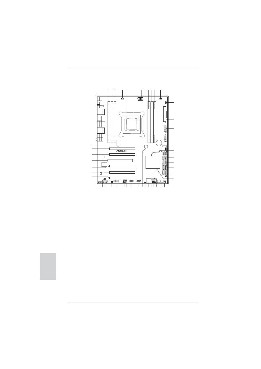
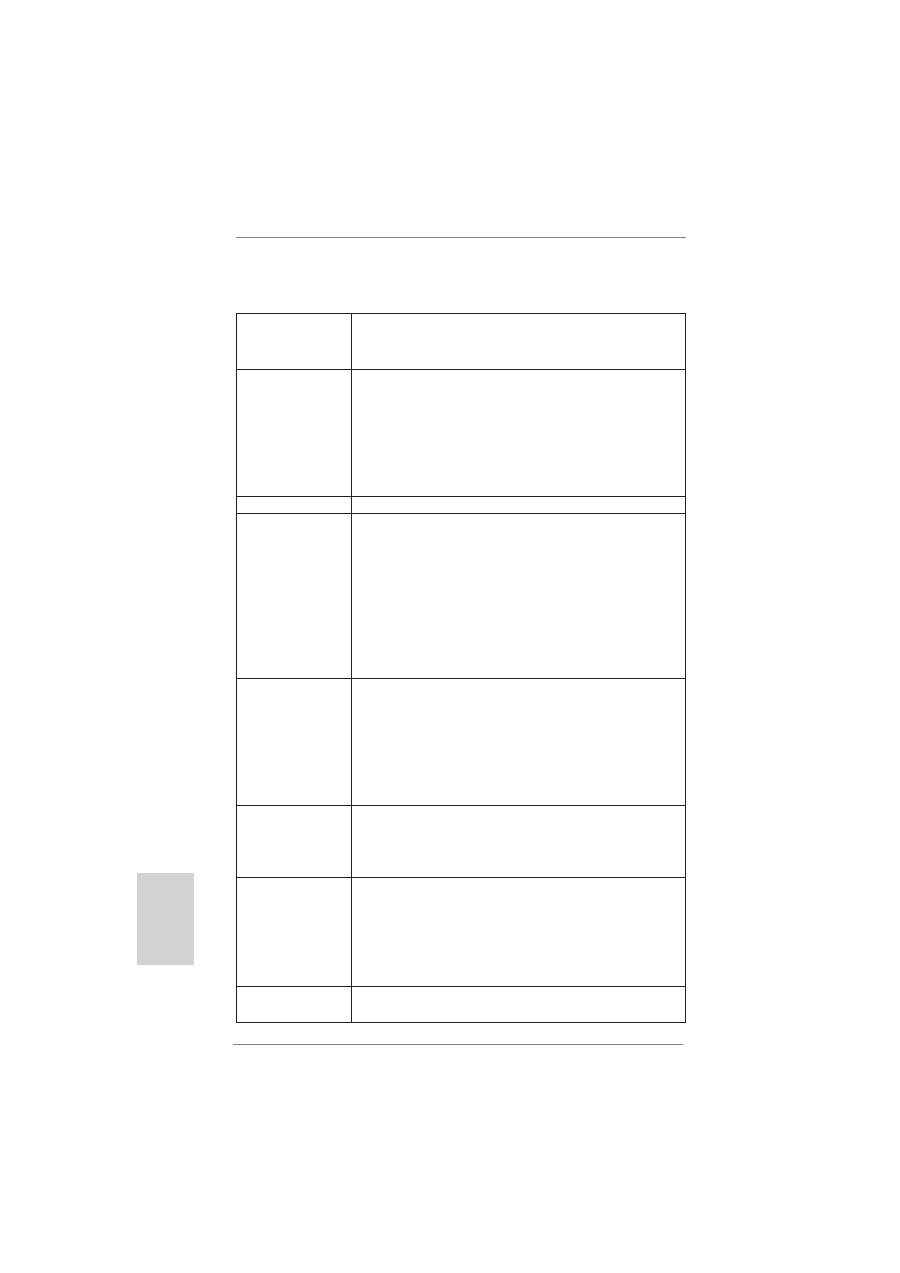
Motherboard Layout
1
240-pin DDR3 DIMM Slot (DDR3_A1, Black)
28
Chassis Speaker Header (SPEAKER1, Black)
2
240-pin DDR3 DIMM Slot (DDR3_B2, Black)
29
System Panel Header (PANEL1, Black)
3
240-pin DDR3 DIMM Slot (DDR3_B1, Black)
30
Power LED Header (PLED1)
4
CPU Fan Connector (CPU_FAN1)
31
Dr. Debug
5
2011-Pin CPU Socket
32
Clear CMOS Jumper (CLRCMOS1)
6
ATX 12V Power Connector (ATX12V1)
33
SPI Flash Memory (64Mb)
7
240-pin DDR3 DIMM Slot (DDR3_D1, Black)
34
USB 2.0 Header (USB_10_11, Black)
8
240-pin DDR3 DIMM Slot (DDR3_D2, Black)
35
USB 2.0 Header (USB_8_9, Black)
9
240-pin DDR3 DIMM Slot (DDR3_C1, Black)
36
USB 2.0 Header (USB_6_7, Black)
10
CPU Fan Connector (CPU_FAN2)
37
Consumer Infrared Module Header
11
Power Fan Connector (PWR_FAN1)
(CIR1, Gray)
12
ATX Power Connector (ATXPWR1)
38
COM Port Header (COM1)
13
USB 3.0 Header (USB3_4_5, Black)
39
Infrared Module Header (IR1)
14
USB 3.0 Header (USB3_2_3, Black)
40
Front Panel IEEE 1394 Header
15
SATA3 Connector (SATA3_M4, Gray)
(FRONT_1394, Black)
16
Chassis Fan Connector (CHA_FAN1)
41
HDMI_SPDIF Header
17
SB Fan Connector (SB_FAN1)
(HDMI_SPDIF1, Black)
18
SATA2 Connectors (SATA2_2_3, Black)
42
Front Panel Audio Header
19
SATA2 Connectors (SATA2_0_1, Black)
(HD_AUDIO1, Black)
20
SATA3 Connectors (SATA3_0_1, Gray)
43
PCI Express 3.0 x16 Slot (PCIE5, Black)
21
SATA3 Connectors (SATA3_M2_M3, Gray)
44
PCI Express 3.0 x16 Slot (PCIE4, Black)
22
SATA3 Connectors (SATA3_M0_M1, Gray)
45
PCI Express 3.0 x16 Slot (PCIE3, Black)
23
Chassis Fan Connector (CHA_FAN3)
46
PCI Slot (PCI1, Black)
24
Intel X79 Chipset
47
PCI Express 3.0 x16 Slot (PCIE2, Black)
25
Chassis Fan Connector (CHA_FAN2)
48
PCI Express 3.0 x16 Slot (PCIE1, Black)
26
Reset Switch (RSTBTN)
49
SLI / XFIRE Power Connector
27
Power Switch (PWRBTN)
DDR3_A1
(64
bit,
240-pin
module)
DDR3_B2
(64
bit,
240-pin
module)
ATX12V1
PS2
Mouse
PS2
Keyboard
Clr
CMOS
Coaxial
SPDIF
Optical
SPDIF
USB 2.0
T: USB2
B: USB3
Top:
RJ-45
USB 3.0
T: USB0
B: USB1
USB
2.0
T:
U
S
B
4
B:
USB5
eSA
TA3
IEEE
1394
T
op:
SIDE
SPK
Center:
REAR
SPK
Bottom:
CTR
BASS
T
op:
LINE
IN
Center:
FRONT
Bottom:
MIC
IN
SLI/XFIRE_PWR1
A
TXPWR1
PWR_FAN1
CPU_FAN1
CPU_FAN2
CHA_F
AN1
1
USB3_2_3
CHA_F
AN3
Intel
X79
PCIE1
PCI1
Super
I/O
LAN
PHY
AUDIO
CODEC
CMOS
Battery
SA
T
A3_M0_M1
64Mb
BIOS
24.4cm (9.6 in)
30.5cm
(12.0
in)
Dr.
Debug
PWRBTN1
RSTBTN1
HDLED RESET
PLED PWRBTN
PANEL1
1
1
SPEAKER1
PLED1
1
SB_FAN1
CLRCMOS1
1
CHA_FAN2
FRONT_1394
1
IR1
1
COM1
1
1
HD_AUDIO1
1
HDMI_SPDIF1
USB_6_7
1
CIR1
1
USB_8_9
1
USB_10_11
1
Designed
in
T
aipei
4
Channels
DDR3
SATA3 6Gb/s
Front
USB
3.0
ErP/EuP Ready
1394a
USB 3.0
3-Way SLI
RoHS
X79 Extreme7
1
2
3
4
5
6
7
8
9
10
11
12
13
14
15
16
17
18
19
20
21
22
23
24
25
26
27
28
29
30
31
32
33
34
35
36
37
38
39
40
41
42
43
44
X
Fast USB
2 oz Copper PCB
PCIE2
PCIE3
PCIE4
PCIE5
X
Fast LAN
LAN
PHY
DDR3_B1
(64
bit,
240-pin
module)
DDR3_D1
(64
bit,
240-pin
module)
DDR3_D2
(64
bit,
240-pin
module)
DDR3_C1
(64
bit,
240-pin
module)
SA
T
A3_M2_M3
SA
T
A3_0_1
SA
T
A2_0_1
SA
T
A2_2_3
SATA3_M4
DDR3
2400+
Top:
RJ-45
USB 2.0
T: USB0
B: USB1
1
USB3_4_5
45
46
47
48
PCI Express 3.0 Ready
49
3
ASRock X79 Extreme7 Motherboard
English
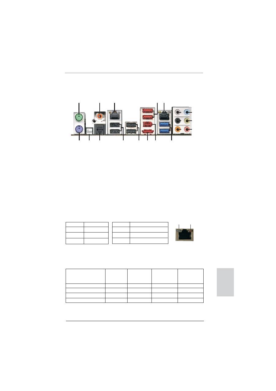
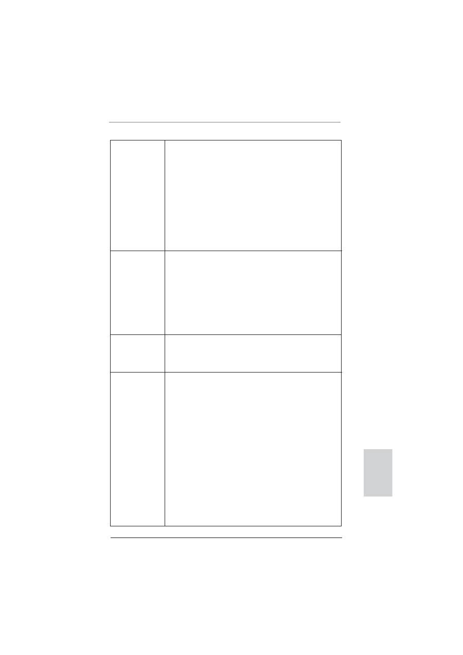
I/O Panel
* There are two LED next to the LAN port. Please refer to the table below for the LAN port LED
indications.
LAN Port LED Indications
Activity/Link LED
SPEED LED
Status Description Status Description
Off No Link Off 10Mbps connection
Blinking Data Activity Orange 100Mbps connection
On Link
Green 1Gbps connection
1
PS/2 Mouse Port (Green)
11 Microphone (Pink)
2
Coaxial SPDIF Out Port
12 USB 3.0 Ports (USB3_0_1)
* 3
LAN RJ-45 Port
13 IEEE 1394 Port (IEEE 1394)
4
USB 2.0 Ports (USB45) *** 14 eSATA3 Connector
* 5
LAN RJ-45 Port
15 USB 2.0 Ports (USB23)
6
Side Speaker (Gray)
16 USB 2.0 Ports (USB01)
7
Rear Speaker (Black)
17 Optical SPDIF Out Port
8
Central / Bass (Orange)
18 Clear CMOS Switch (CLRCBTN)
9
Line In (Light Blue)
19 PS/2 Keyboard Port (Purple)
** 10
Front Speaker (Lime)
ACT/LINK
LED
SPEED
LED
LAN Port
**
If you use 2-channel speaker, please connect the speaker’s plug into “Front Speaker Jack”.
See the table below for connection details in accordance with the type of speaker you use.
TABLE for Audio Output Connection
Audio Output Channels Front Speaker Rear Speaker Central / Bass Side Speaker
(No. 10)
(No. 7) (No. 8) (No. 6)
2
V
-- -- --
4 V
V
--
--
6
V
V V --
8
V
V V V
1
2
3
4
10
5
6
7
8
9
13
11
12
14
15
16
17
18
19
4
ASRock X79 Extreme7 Motherboard
English
To enable Multi-Streaming function, you need to connect a front panel audio cable to the front
panel audio header. After restarting your computer, you will
fi
nd “Mixer” tool on your system.
Please select “Mixer ToolBox” , click “Enable playback multi-streaming”, and click
“ok”. Choose “2CH”, “4CH”, “6CH”, or “8CH” and then you are allowed to select “Realtek HDA
Primary output” to use Rear Speaker, Central/Bass, and Front Speaker, or select “Realtek
HDA Audio 2nd output” to use front panel audio.
*** eSATA3 connector supports SATA Gen3 in cable 1M.
5
ASRock X79 Extreme7 Motherboard
1. Introduction
Thank you for purchasing ASRock
X79 Extreme7
motherboard, a reliable moth-
erboard produced under ASRock’s consistently stringent quality control. It delivers
excellent performance with robust design conforming to ASRock’s commitment to
quality and endurance.
This Quick Installation Guide contains introduction of the motherboard and step-by-
step installation guide. More detailed information of the motherboard can be found
in the user manual presented in the Support CD.
Because the motherboard speci
fi
cations and the BIOS software might be
updated, the content of this manual will be subject to change without no-
tice. In case any modi
fi
cations of this manual occur, the updated version
will be available on ASRock website without further notice. You may
fi
nd
the latest VGA cards and CPU support lists on ASRock website as well.
ASRock website http://www.asrock.com
If you require technical support related to this motherboard, please visit
our website for speci
fi
c information about the model you are using.
www.asrock.com/support/index.asp
1.1 Package Contents
ASRock
X79 Extreme7
Motherboard
(ATX Form Factor: 12.0-in x 9.6-in, 30.5 cm x 24.4 cm)
ASRock
X79 Extreme7
Quick Installation Guide
ASRock
X79 Extreme7
Support CD
6 x Serial ATA (SATA) Data Cables (Optional)
2 x Serial ATA (SATA) HDD Power Cables (Optional)
1 x I/O Panel Shield
1 x Front USB 3.0 Panel
4 x HDD Screws
6 x Chassis Screws
1 x Rear USB 3.0 Bracket
1 x ASRock SLI_Bridge_2S Card
1 x ASRock 3-Way SLI-2S1S Bridge Card
English
ASRock Reminds You...
To get better performance in Windows
®
7 / 7 64-bit / Vista
TM
/ Vista
TM
64-
bit, it is recommended to set the BIOS option in Storage Con
fi
guration to
AHCI mode. For the BIOS setup, please refer to the “User Manual” in our
support CD for details.
6
ASRock X79 Extreme7 Motherboard
English
1.2 Specifications
Platform
- ATX Form Factor: 12.0-in x 9.6-in, 30.5 cm x 24.4 cm
- Premium Gold Capacitor design (100% Japan-made high-
quality Conductive Polymer Capacitors)
CPU
- Supports Intel
®
Core
TM
i7-39xx & 38xx Series Processors in
Socket LGA 2011
- Digi Power Design
- Advanced V12 + 2 Power Phase Design
- Supports Intel
®
Turbo Boost 2.0 Technology
- Supports Hyper-Threading Technology (see
CAUTION 1
)
- Supports Untied Overclocking Technology
Chipset
- Intel
®
X79
Memory
- Quad Channel DDR3 Memory Technology (see
CAUTION 2
)
- 6 x DDR3 DIMM slots (see
CAUTION 3
)
- Supports DDR3 2400+(OC)/1600/1333/1066/800 non-ECC,
un-buffered memory
- Supports DDR3 ECC, un-buffered memory with Intel
®
Workstation 1S Xeon
®
processors E5 2xxx & 4xxx series in
socket LGA 2011
- Max. capacity of system memory: 48GB (see
CAUTION 4
)
- Supports Intel
®
Extreme Memory Pro
fi
le (XMP)1.3/1.2
Expansion Slot
- 5 x PCI Express 3.0 x16 slots (PCIE1/PCIE2/PCIE3/PCIE4/
PCIE5: x8/8/8/8/8 mode or x16/0/16/0/8 mode)
(see
CAUTION 5
)
- 1 x PCI slot
-
Supports
AMD
TM
Quad CrossFireX
TM
, 3-Way CrossFireX
TM
and CrossFireX
TM
- Supports NVIDIA
®
Quad SLI
TM
, 3-Way SLI
TM
and SLI
TM
Audio
- 7.1 CH HD Audio with Content Protection
(Realtek ALC898 Audio Codec)
- Premium Blu-ray audio support
- Supports THX TruStudio
TM
LAN
- PCIE x1 Gigabit LAN 10/100/1000 Mb/s
- Broadcom BCM57781
- Supports Wake-On-LAN
- Supports Energy Ef
fi
cient Ethernet 802.3az
- Supports Dual LAN with Teaming function
- Supports PXE
Rear Panel I/O
I/O Panel
- 1 x PS/2 Mouse Port
7
ASRock X79 Extreme7 Motherboard
English
- 1 x PS/2 Keyboard Port
- 1 x Coaxial SPDIF Out Port
- 1 x Optical SPDIF Out Port
- 6 x Ready-to-Use USB 2.0 Ports
- 1 x eSATA3 Connector
- 2 x Ready-to-Use USB 3.0 Ports
- 2 x RJ-45 LAN Ports with LED (ACT/LINK LED and SPEED
LED)
- 1 x IEEE 1394 Port
- 1 x Clear CMOS Switch with LED
- HD Audio Jack: Side Speaker/Rear Speaker/Central/Bass/
Line in/Front Speaker/Microphone (see
CAUTION 6
)
SATA3
- 2 x SATA3 6.0 Gb/s connectors by Intel
®
X79, support RAID
(RAID 0, RAID 1, RAID 5, RAID 10 and Intel Rapid
Storage 3.0), NCQ, AHCI and "Hot Plug" functions
- 2 x SATA3 6.0 Gb/s connectors by Marvell SE9182, support
RAID (RAID 0 and RAID 1), NCQ, AHCI and “Hot Plug”
functions
- 3 x SATA3 6.0 Gb/s connectors by Marvell SE9172, support
RAID (RAID 0 and RAID 1), NCQ, AHCI and “Hot Plug”
functions
USB3.0
- 2 x Rear USB 3.0 ports by ASMedia ASM1042, support
USB 1.0/2.0/3.0 up to 5Gb/s
- 2 x Front USB 3.0 headers (support 4 USB 3.0 ports) by TI
®
,
supports USB 1.0/2.0/3.0 up to 5Gb/s
Connector
- 4 x SATA2 3.0 Gb/s connectors, support RAID (RAID 0,
RAID 1, RAID 5, RAID 10 and Intel Rapid Storage 3.0),
NCQ, AHCI and Hot Plug functions
- 7 x SATA3 6.0Gb/s connectors
- 1 x IR header
- 1 x CIR header
- 1 x COM port header
- 1 x HDMI_SPDIF header
- 1 x IEEE 1394 header
- 1 x Power LED header
- CPU/Chassis/Power/SB FAN connector
- 24 pin ATX power connector
- 8 pin 12V power connector
- SLI/XFire power connector
- Front panel audio connector
- 3 x USB 2.0 headers (support 6 USB 2.0 ports)
8
ASRock X79 Extreme7 Motherboard
English
- 2 x USB 3.0 headers (support 4 USB 3.0 ports)
- 1 x Dr. Debug with LED
Smart Switch
- 1 x Clear CMOS Switch with LED
- 1 x Power Switch with LED
- 1 x Reset Switch with LED
BIOS Feature
- 64Mb AMI UEFI Legal BIOS with GUI support
- Supports “Plug and Play”
- ACPI 1.1 Compliance Wake Up Events
- Supports jumperfree
- SMBIOS 2.3.1 Support
- CPU, VCCSA, DRAM, VTT, CPU PLL, PCH1.1V, PCH1.5V
Voltage Multi-adjustment
Support CD
- Drivers, Utilities, AntiVirus Software (Trial Version),
CyberLink MediaEspresso 6.5 Trial, ASRock Software Suite
(ASRock MAGIX Multimedia Suite - OEM)
Unique Feature
- ASRock Extreme Tuning Utility (AXTU) (see
CAUTION 7
)
- ASRock Instant Boot
- ASRock Instant Flash (see
CAUTION 8
)
- ASRock APP Charger (see
CAUTION 9
)
- ASRock SmartView (see
CAUTION 10
)
- ASRock XFast USB (see
CAUTION 11
)
- ASRock XFast LAN (see
CAUTION 12
)
- ASRock XFast Charger (see
CAUTION 13
)
- ASRock XFast RAM (see
CAUTION 14
)
- ASRock X-FAN (see
CAUTION 15
)
- ASRock Crashless BIOS (see
CAUTION 16
)
- Hybrid Booster:
- CPU Frequency Stepless Control (see
CAUTION 17
)
- ASRock U-COP (see
CAUTION 18
)
- Boot Failure Guard (B.F.G.)
- Good Night LED
Hardware
- CPU Temperature Sensing
Monitor
- Chassis Temperature Sensing
- CPU/Chassis/Power/SB Fan Tachometer
- CPU/Chassis Quiet Fan (Allows Chassis Fan Speed Auto-
Adjust by CPU Temperature)
- CPU/Chassis/SB Fan Multi-Speed Control
- Voltage Monitoring: +12V, +5V, +3.3V, CPU Vcore
OS
-
Microsoft
®
Windows
®
7 / 7 64-bit / Vista
TM
/ Vista
TM
64-bit
/ XP / XP 64-bit compliant (see
CAUTION 19
)
Certi
fi
cations
- FCC, CE, WHQL

9
ASRock X79 Extreme7 Motherboard
English
CAUTION!
1. About the setting of “Hyper Threading Technology”, please check page
68 of “User Manual” in the support CD.
2. This motherboard supports Quad Channel Memory Technology. Before
you implement Quad Channel Memory Technology, make sure to read
the installation guide of memory modules on page 16 for proper installa-
tion.
3. Due to Intel
®
CPU spec de
fi
nition, the system will not boot if only two
DIMM are installed into DDR3_B2 and DDR3_D2 slots. Please install the
memory modules into DDR3_B1 and DDR3_D1 slots
fi
rst, then DDR3_
B2 and DDR3_D2 slots can work properly.
4. Due to the operating system limitation, the actual memory size may be
less than 4GB for the reservation for system usage under Windows
®
7 /
Vista
TM
/ XP. For Windows
®
OS with 64-bit CPU, there is no such limita-
tion. You can use ASRock XFast RAM to utilize the memory that Win-
dows
®
cannot use.
5. Currently
Intel
®
Socket 2011 Sandy Bridge-E Processor doesn’t support
PCIE 3.0, but this motherboard is already PCIE 3.0 hardware ready. It
depends on Intel’s CPU to enable PCIE 3.0. Please check Intel’s website
for information on future CPU updates and releases.
6. For microphone input, this motherboard supports both stereo and mono
modes. For audio output, this motherboard supports 2-channel, 4-chan-
nel, 6-channel, and 8-channel modes. Please check the table on page 3
for proper connection.
7. ASRock Extreme Tuning Utility (AXTU) is an all-in-one tool to ne-tune dif-
ferent system functions in a user-friendly interface, which includes Hard-
ware Monitor, Fan Control, Overclocking, OC DNA and IES. In Hardware
Monitor, it shows the major readings of your system. In Fan Control, it
shows the fan speed and temperature for you to adjust. In Overclocking,
you are allowed to overclock CPU frequency for optimal system perfor-
mance. In OC DNA, you can save your OC settings as a pro
fi
le and share
it with your friends. Your friends then can load the OC pro
fi
le to their own
system to get the same OC settings. In IES (Intelligent Energy
WARNING
Please realize that there is a certain risk involved with overclocking, including
adjusting the setting in the BIOS, applying Untied Overclocking Technology, or
using the third-party overclocking tools. Overclocking may affect your system
stability, or even cause damage to the components and devices of your system.
It should be done at your own risk and expense. We are not responsible for possible
damage caused by overclocking.
- ErP/EuP Ready (ErP/EuP ready power supply is required)
(see
CAUTION 20
)
* For detailed product information, please visit our website: http://www.asrock.com

10
ASRock X79 Extreme7 Motherboard
English
Saver), the voltage regulator can reduce the number of output phases to
improve ef
fi
ciency when the CPU cores are idle without sacri
fi
cing
computing performance. Please visit our website for the operation proce-
dures of ASRock Extreme Tuning Utility (AXTU).
ASRock website: http://www.asrock.com
8. ASRock Instant Flash is a BIOS
fl
ash utility embedded in Flash ROM.
This convenient BIOS update tool allows you to update system BIOS
without entering operating systems
fi
rst like MS-DOS or Windows
®
. With
this utility, you can press the <F6> key during the POST or the <F2>
key to enter into the BIOS setup menu to access ASRock Instant Flash.
Just launch this tool and save the new BIOS
fi
le to your USB
fl
ash drive,
fl
oppy disk or hard drive, then you can update your BIOS only in a few
clicks without preparing an additional
fl
oppy diskette or other complicated
fl
ash utility. Please be noted that the USB
fl
ash drive or hard drive must
use FAT32/16/12
fi
le system.
9. If you desire a faster, less restricted way of charging your Apple devices,
such as iPhone/iPad/iPod Touch, ASRock has prepared a wonderful solu-
tion for you - ASRock APP Charger. Simply install the APP Charger
driver, it makes your iPhone charge much quickly from your computer and
up to 40% faster than before. ASRock APP Charger allows you to quickly
charge many Apple devices simultaneously and even supports continu-
ous charging when your PC enters into Standby mode (S1), Suspend to
RAM (S3), hibernation mode (S4) or power off (S5). With APP Charger
driver installed, you can easily enjoy the marvelous charging experience.
ASRock website: http://www.asrock.com/Feature/AppCharger/index.asp
10. ASRock SmartView, a new function for internet browsers, is the smart
start page for IE that combines your most visited web sites, your history,
your Facebook friends and your real-time newsfeed into an enhanced
view for a more personal Internet experience. ASRock motherboards are
exclusively equipped with the ASRock SmartView utility that helps you
keep in touch with friends on-the-go. To use ASRock SmartView feature,
please make sure your OS version is Windows
®
7 / 7 64 bit / Vista
TM
/
Vista
TM
64 bit, and your browser version is IE8.
ASRock website: http://www.asrock.com/Feature/SmartView/index.asp
11. ASRock XFast USB can boost USB storage device performance. The
performance may depend on the properties of the device.
12. ASRock XFast LAN provides a faster internet access, which includes
the bene
fi
ts listed below. LAN Application Prioritization: You can con
fi
g-
ure your application’s priority ideally and/or add new programs. Lower
Latency in Game: After setting online game’s priority higher, it can lower
the latency in games. Traf
fi
c Shaping: You can watch Youtube HD videos
and download simultaneously. Real-Time Analysis of Your Data: With
the status window, you can easily recognize which data streams you are
transferring currently.

11
ASRock X79 Extreme7 Motherboard
English
13. ASRock XFast Charger is the best and fastest technology to charge your
mobile devices via PC. With the superb XFast Charger USB port, users
are assured to enjoy the quick charging experience anytime. In addi-
tion to Apple devices, it is also capable of Charging the BC 1.1 standard
smart devices. Please refer to page 32 for details.
14. ASRock XFast RAM is a new function that is included into ASRock Ex-
treme Tuning Utility (AXTU). It fully utilizes the memory space that can-
not be used under Windows
®
OS 32-bit CPU. ASRock XFast RAM also
shortens the loading time of previously visited websites, making web surf-
ing faster than ever. And it also boosts the speed of Adobe Photoshop 5
times faster. Another advantage of ASRock XFast RAM is that it reduces
the frequency of accessing your SSDs or HDDs in order to extend their
lifespan.
15. ASRock X-FAN will be automatically activated only when the system
rises to a certain temperature under heavy-loading or overclocking. Nor-
mally, ASRock X-FAN will remain deactivated to give users the quietest
computing experience. The target temperature and fan speed settings
can be con
fi
gured in the UEFI setup utility.
16. ASRock Crashless BIOS allows users to update their BIOS without fear
of failing. If power loss occurs during the BIOS update process, ASRock
Crashless BIOS will automatically
fi
nish the BIOS update procedure after
regaining power. Please note that BIOS
fi
les need to be placed in the
root directory of your USB disk. Only USB2.0 ports support this feature.
17. Although this motherboard offers stepless control, it is not recommended
to perform over-clocking. Frequencies other than the recommended CPU
bus frequencies may cause instability of the system or damage the CPU.
18. While CPU overheat is detected, the system will automatically shutdown.
Before you resume the system, please check if the CPU fan on the moth-
erboard functions properly and unplug the power cord, then plug it back
again. To improve heat dissipation, remember to spray thermal grease
between the CPU and the heatsink when you install the PC system.
19. Intel Rapid Storage Technology enterprise 3.0 is not supported by Micro-
soft
®
Windows
®
XP / XP 64-bit.
20. EuP stands for Energy Using Product, was a provision regulated by the
European Union to de
fi
ne the power consumption for the completed sys-
tem. According to EuP, the total AC power of the completed system
should be under 1.00W in off mode condition. To meet EuP standards,
an EuP ready motherboard and an EuP ready power supply are required.
According to Intel’s suggestion, the EuP ready power supply must meet
the standard of 5v, and the standby power ef
fi
ciency should be higher
than 50% under 100 mA current consumption. For EuP ready power sup-
ply selection, we recommend you to check with the power supply manu-
facturer for more details.
Оглавление
- 1. Introduction
- 2. Installation
- 3. BIOS Information
- 1. Einführung
- 2. BIOS-Information
- 1. Introduction
- 2. Informations sur le BIOS
- 1. Introduzione
- 2. Informazioni sul BIOS
- 1. Introducción
- 2. BIOS Información
- 1. Введение
- 2.
- 1. Giri ş
- 2. BIOS Bilgileri
- 1. 제품소개
- 2. 시스템 바이오스 정보
- 1. 主板簡介
- 2. BIOS 信息
- 1. 主機板簡介
- 2. BIOS 訊息
- 1. Penjelasan
- Installing OS on a HDD Larger Than 2TB
