ASRock Z87 OC Formula__ac: инструкция
Раздел: Компьютерная техника, комплектующие, аксессуары
Тип: Материнская Плата
Инструкция к Материнской Плате ASRock Z87 OC Formula__ac

Version 1.0
Published May 2013
Copyright©2013 ASRock INC. All rights reserved.
Copyright Notice:
No part of this documentation may be reproduced, transcribed, transmitted, or
translated in any language, in any form or by any means, except duplication of
documentation by the purchaser for backup purpose, without written consent of
ASRock Inc.
Products and corporate names appearing in this documentation may or may not
be registered trademarks or copyrights of their respective companies, and are used
only for identication or explanation and to the owners’ benet, without intent to
infringe.
Disclaimer:
Specications and information contained in this documentation are furnished for
informational use only and subject to change without notice, and should not be
constructed as a commitment by ASRock. ASRock assumes no responsibility for
any errors or omissions that may appear in this documentation.
With respect to the contents of this documentation, ASRock does not provide
warranty of any kind, either expressed or implied, including but not limited to
the implied warranties or conditions of merchantability or tness for a particular
purpose.
In no event shall ASRock, its directors, ocers, employees, or agents be liable for
any indirect, special, incidental, or consequential damages (including damages for
loss of prots, loss of business, loss of data, interruption of business and the like),
even if ASRock has been advised of the possibility of such damages arising from any
defect or error in the documentation or product.
is device complies with Part 15 of the FCC Rules. Operation is subject to the following
two conditions:
(1) this device may not cause harmful interference, and
(2) this device must accept any interference received, including interference that
may cause undesired operation.
CALIFORNIA, USA ONLY
e Lithium battery adopted on this motherboard contains Perchlorate, a toxic substance
controlled in Perchlorate Best Management Practices (BMP) regulations passed by the
California Legislature. When you discard the Lithium battery in California, USA, please
follow the related regulations in advance.
“Perchlorate Material-special handling may apply, see www.dtsc.ca.gov/hazardouswaste/
perchlorate”
ASRock Website: http://www.asrock.com
e terms HDMI™ and HDMI High-Denition Multimedia Interface, and the HDMI
logo are trademarks or registered trademarks of HDMI Licensing LLC in the United
States and other countries.
Manufactured under license under U.S. Patent Nos: 5,956,674; 5,974,380; 6,487,535;
7,003,467 & other U.S. and worldwide patents issued & pending. DTS, the Symbol, &
DTS and the Symbol together is a registered trademark & DTS Connect, DTS Interactive,
DTS Neo:PC are trademarks of DTS, Inc. Product includes soware.
© DTS, Inc., All Rights Reserved.
Z87 OC Formula/ac / Z87 OC Formula
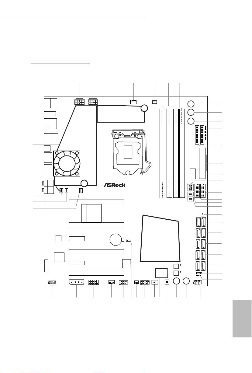
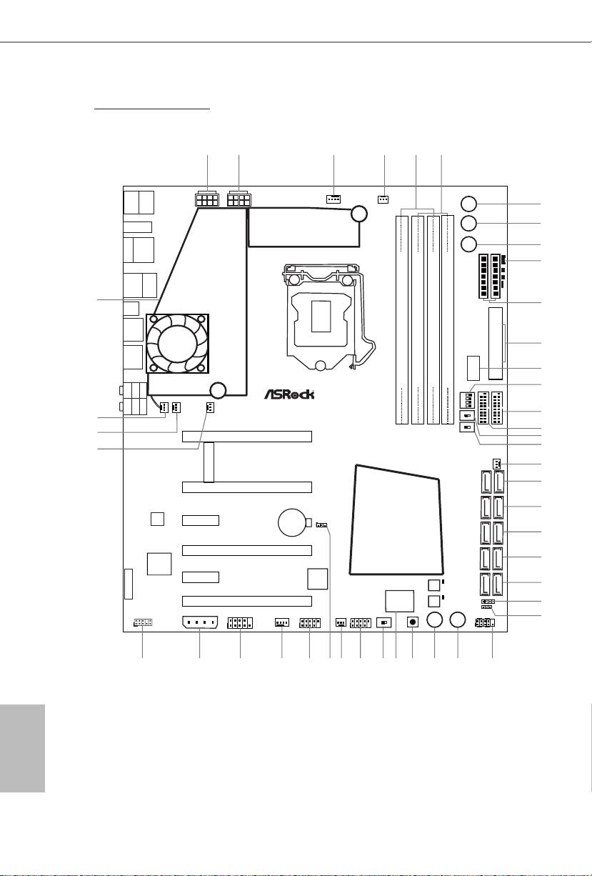
Motherboard Layout
English
PB 1
1
2
3
4
5
6
ATX12V1
ATX12V3
/Mouse
Keyb oa rd
B: USB1
T: USB0
USB 2.0
PS2
CPU_FAN1
CPU_FAN2
7
+
8
HDMI2
-
HDMI1
USB 3.0
MENU
9
T: USB0
B: USB1
10
USB 3.0
T: USB2
Top:
RJ-45
B: USB3
44
CMOS
Clr
11
USB 3.0
T: USB4
B: USB5
12
USB 3.0
USB3_12
T: USB6
B: USB7
ATXPWR1
13
DDR3_A1 (64 bit, 240-pin module)
DDR3_A2 (64 bit, 240-pin module)
DDR3_B1 (64 bit, 240-pin module)
DDR3_B2 (64 bit, 240-pin module)
Verti ca l
Type A US B
SPDI F
Opti cal
Bott om:
REAR S PK
Cent er:
Cent ral/B ass
Top:
14
USB3_10_11
USB3_8_9
1 2 3 4
ON
MIC IN
Bott om:
FRON T
Cent er:
LINE I N
Top:
CHA_FAN4MOS_FAN1
SLOWMODE1
PWR_FAN1
OFF
ON
15
43
OFF
ON
16
42
PCIE1
LN2MODE1
17
WiFi-802.11n
MINI_PCIE1
18
41
Module
CHA_FAN3
19
20
PCIE2
Z87 OC Formula
21
LAN
Intel
PCIE3
CMOS
CLRCMOS1
Battery
1
22
Z87
PCIE4
23
Purity
RoHS
Sound
TM
PCIE5
Super
BIOS_B_LED
I/O
64Mb
24
BIOS
8-La yer P CB
BIOS_B
SATA3 _A 3_ A4 S ATA3_ A1 _A2 SATA 3_ 0_ 1 SATA3 _2 _3 S ATA3 _4 _5
Statu s
BIOS_A_LED
64Mb
PCIE6
BIOS
SPEAKER1
1
OLED
25
BIOS_A
PLED1
1
SLI/XFIRE_PWR1
HD_AUDIO1
COM1
CHA_FAN1
USB4_5
CHA_FAN2
USB2_3
BIOS _SEL1
CLRCBTN2
PANEL1
PLED PWRBTN
26
Reset Power
1
AB
1
1
1
1
HDLED RESET
39
3840
36
35
32
31
30
2829333437
27
Z87 OC Formula/ac
Z87 OC Formula/ac / Z87 OC Formula
English
2 PB
1
2
3
4
5
6
Keyb oa rd
ATX12V1
ATX12V3
/Mouse
B: USB1
T: USB0
USB 2.0
PS2
CPU_FAN1
CPU_FAN2
7
+
8
HDMI2
-
HDMI1
USB 3.0
MENU
9
T: USB0
B: USB1
10
USB 3.0
T: USB2
Top:
RJ-45
B: USB3
44
CMOS
Clr
11
USB 3.0
T: USB4
B: USB5
12
USB 3.0
USB3_12
T: USB6
B: USB7
ATXPWR1
13
DDR3_A1 (64 bit, 240-pin module)
DDR3_A2 (64 bit, 240-pin module)
DDR3_B1 (64 bit, 240-pin module)
DDR3_B2 (64 bit, 240-pin module)
Verti ca l
Type A US B
SPDI F
Opti cal
Bott om:
REAR S PK
Cent er:
Cent ral/B ass
Top:
14
USB3_10_11
USB3_8_9
1 2 3 4
ON
MIC IN
Bott om:
FRON T
Cent er:
LINE I N
Top:
CHA_FAN4MOS_FAN1
SLOWMODE1
PWR_FAN1
OFF
ON
15
43
OFF
ON
16
42
LN2MODE1
PCIE1
17
18
41
CHA_FAN3
19
MINI_ PCIE 1
20
PCIE2
Z87 OC Formula
21
LAN
Intel
PCIE3
CMOS
CLRCMOS1
Battery
1
22
Z87
PCIE4
23
Purity
Sound
TM
RoHS
PCIE5
Super
BIOS_B_LED
I/O
64Mb
24
BIOS
8-La yer P CB
BIOS_B
Statu s
BIOS_A_LED
SATA3 _A 3_ A4 S ATA3_ A1 _A2 SATA 3_ 0_ 1 SATA3 _2 _3 S ATA3 _4 _5
64Mb
PCIE6
BIOS
SPEAKER1
1
OLED
25
BIOS_A
PLED1
1
SLI/XFIRE_PWR1
HD_AUDIO1
COM1
CHA_FAN1
USB4_5
CHA_FAN2
USB2_3
BIOS _SEL1
CLRCBTN2
PANEL1
PLED PWRBTN
26
Reset Power
1
AB
1
1
1
1
HDLED RESET
39
3840
36
35
32
31
30
2829333437
27
Z87 OC Formula

Z87 OC Formula/ac / Z87 OC Formula
No. Description
1 ATX 12V Power Connector (ATX12V1)
2 ATX 12V Power Connector (ATX12V3)
3 CPU Fan Connector (CPU_FAN1)
4 CPU Fan Connector (CPU_FAN2)
5 2 x 240-pin DDR3 DIMM Slots (DDR3_A1, DDR3_B1)
6 2 x 240-pin DDR3 DIMM Slots (DDR3_A2, DDR3_B2)
7 Rapid OC Button (+)
8 Rapid OC Button (–)
9 Menu Button (MENU1)
10 Post Status Checker (PSC)
TM
11 V-Probe
(VOL_CON1, VOL_CON2)
12 ATX Power Connector (ATXPWR1)
13 Vertical Type A USB 3.0 (USB3_12)
14 PCIe ON/OFF Switch
15 USB 3.0 Header (USB3_8_9) (ASMedia Hub)
16 USB 3.0 Header (USB3_10_11) (ASMedia Hub)
17 Slow Mode Switch
18 LN2 Mode Switch(LN2MODE1)
19 Chassis Fan Connector (CHA_FAN3)
20 SATA3 Connectors (SATA3_A3_A4)
21 SATA3 Connectors (SATA3_A1_A2)
22 SATA3 Connectors (SATA3_0_1)
23 SATA3 Connectors (SATA3_2_3)
24 SATA3 Connectors (SATA3_4_5)
25 Chassis Speaker Header (SPEAKER1)
26 Power LED Header (PLED1)
27 System Panel Header (PANEL1)
28 Power Switch (PWRBTN1)
29 Reset Switch (RSTBTN1)
30 Clear CMOS Switch
31 Status OLED
32 BIOS Selection Switch (BIOS_SEL1)
English
33 USB 2.0 Header (USB2_3)
PB 3

Z87 OC Formula/ac / Z87 OC Formula
No. Description
34 Chassis Fan Connector (CHA_FAN2)
35 Clear CMOS Jumper (CLRCMOS1)
36 USB 2.0 Header (USB4_5)
37 Chassis Fan Connector (CHA_FAN1)
38 COM Port Header (COM1)
39 SLI/XFIRE Power Connector (SLI/XFIRE_PWR1)
40 Front Panel Audio Header (HD_AUDIO1)
41 Power Fan Connector (PWR_FAN1)
42 Chassis Fan Connector (CHA_FAN4)
43 MOS Fan Connector (MOS_FAN1)
44 Twin-Power Cooling
English
4 5
Z87 OC Formula/ac / Z87 OC Formula
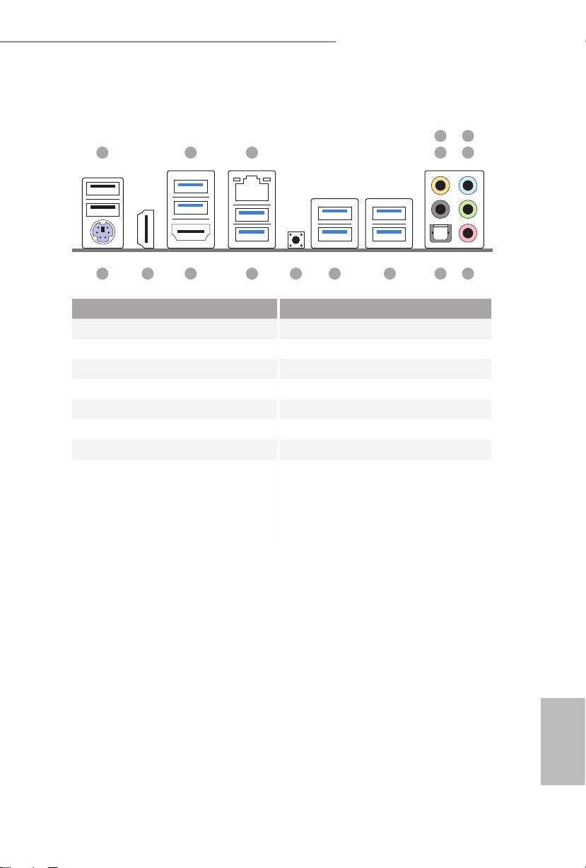
1.5 I/O Panel
4
6
1 2 3 5
7
8910111213141516
No. Description No. Description
1 USB 2.0 Ports (USB01) 9 Optical SPDIF Out Port
2 USB 3.0 Ports (USB3_01) 10 USB 3.0 Ports (USB3_67)
3 LAN RJ-45 Port 11 USB 3.0 Ports (USB3_45)
4 Central / Bass (Orange) 12 Clear CMOS Switch (CLRCBTN)
5 Rear Speaker (Black) 13 USB 3.0 Ports (USB3_23)
6 Line In (Light Blue) 14 HDMI-Out Port
7 Front Speaker (Lime)** 15 HDMI-In Port
8 Microphone (Pink) 16 PS/2 Mouse/Keyboard Port
English
4 5
Z87 OC Formula/ac / Z87 OC Formula
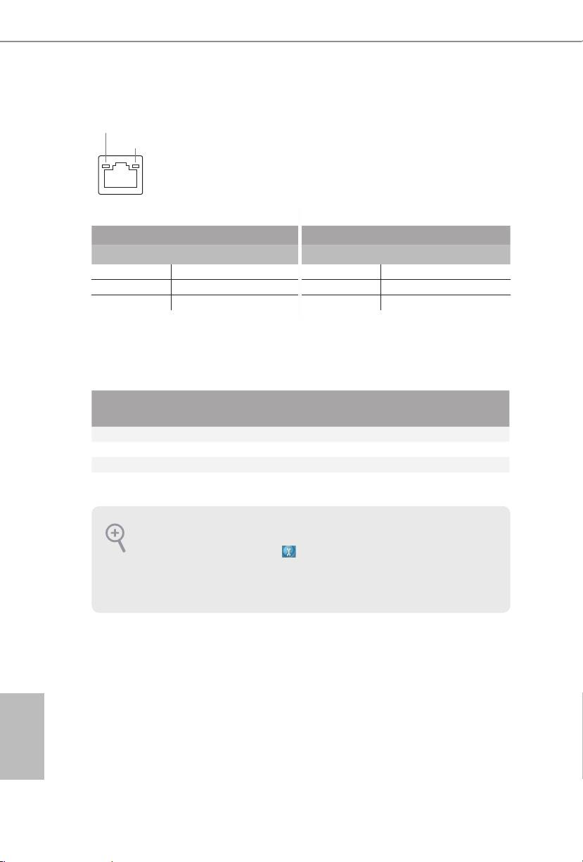
* ere are two LEDs on each LAN port. Please refer to the table below for the LAN port LED indications.
Chapter 1 Introduction
ACT/LINK LED
ank you for purchasing ASRock Z87 OC Formula/ac / Z87 OC Formula
SPEED LED
motherboard, a reliable motherboard produced under ASRock’s consistently
stringent quality control. It delivers excellent performance with robust design
conforming to ASRock’s commitment to quality and endurance.
LAN Port
Activity / Link LED Speed LED
Status Description Status Description
O No Link O 10Mbps connection
Blinking Data Activity Orange 100Mbps connection
On Link Green 1Gbps connection
** If you use a 2-channel speaker, please connect the speaker’s plug into “Front Speaker Jack”. See the table below
1.1 Package Contents
for connection details in accordance with the type of speaker you use.
•
ASRock Z87 OC Formula/ac / Z87 OC Formula Motherboard (EATX Form Factor)
Audio Output
Front Speaker
Rear Speaker
Central / Bass
Line In
•
ASRock Z87 OC Formula/ac / Z87 OC Formula Quick Installation Guide
Channels
(No. 7)
(No. 5)
(No. 4)
(No. 6)
•
ASRock Z87 OC Formula/ac / Z87 OC Formula Support CD
2 V -- -- --
•
10 x Serial ATA (SATA) Data Cables (Optional)
4 V V -- --
•
2 x SATA 1 to 1 Power Cables (Optional)
6 V V V --
•
1 x I/O Panel Shield
8 V V V V
•
1 x ASRock Flexible SLI Bridge Connector Cable
•
1 x Front USB 3.0 Panel with 2.5” HDD/SSD Rack
•
4 x HDD Screws
To enable Multi-Streaming, you need to connect a front panel audio cable to the front
panel audio header. Aer restarting your computer, you will nd the “Mixer” tool on your
•
6 x Chassis Screws
system. Please select “Mixer ToolBox” , click “Enable playback multi-streaming”, and
•
1 x Rear USB 3.0 Bracket
click “ok”. Choose “2CH”, “4CH”, “6CH”, or “8CH” and then you are allowed to select
•
10 x OC Stands
“Realtek HDA Primary output” to use the Rear Speaker, Central/Bass, and Front Speaker,
or select “Realtek HDA Audio 2nd output” to use the front panel audio.
•
GELID Solutions GC-Extreme ermal Compound
•
1 x ASRock WiFi 2.4/5GHz Antenna (for Z87 OC Formula/ac only)
*** e eSATA connector supports SATA3 with cables within 1 meters.
•
2 x SMA Wi-Fi Antenna Cables (for Z87 OC Formula/ac only)
•
1 x WiFi Module Screw (for Z87 OC Formula only)
English
6 7

Z87 OC Formula/ac / Z87 OC Formula
Chapter 1 Introduction
ank you for purchasing ASRock Z87 OC Formula/ac / Z87 OC Formula
motherboard, a reliable motherboard produced under ASRock’s consistently
stringent quality control. It delivers excellent performance with robust design
conforming to ASRock’s commitment to quality and endurance.
Because the motherboard specications and the BIOS soware might be updated, the
content of this documentation will be subject to change without notice. In case any modi-
cations of this documentation occur, the updated version will be available on ASRock’s
website without further notice. If you require technical support related to this mother-
board, please visit our website for specic information about the model you are using. You
may nd the latest VGA cards and CPU support list on ASRock’s website as well. ASRock
website http://www.asrock.com.
1.1 Package Contents
•
ASRock Z87 OC Formula/ac / Z87 OC Formula Motherboard (EATX Form Factor)
•
ASRock Z87 OC Formula/ac / Z87 OC Formula Quick Installation Guide
•
ASRock Z87 OC Formula/ac / Z87 OC Formula Support CD
•
10 x Serial ATA (SATA) Data Cables (Optional)
•
2 x SATA 1 to 1 Power Cables (Optional)
•
1 x I/O Panel Shield
•
1 x ASRock Flexible SLI Bridge Connector Cable
•
1 x Front USB 3.0 Panel with 2.5” HDD/SSD Rack
•
4 x HDD Screws
•
6 x Chassis Screws
•
1 x Rear USB 3.0 Bracket
•
10 x OC Stands
•
GELID Solutions GC-Extreme ermal Compound
•
1 x ASRock WiFi 2.4/5GHz Antenna (for Z87 OC Formula/ac only)
•
2 x SMA Wi-Fi Antenna Cables (for Z87 OC Formula/ac only)
•
1 x WiFi Module Screw (for Z87 OC Formula only)
English
6 7

Z87 OC Formula/ac / Z87 OC Formula
1.2 Specications
Platform
•
EATX Form Factor (12.0-in x 10.5-in, 30.5 cm x 26.7 cm)
•
Premium Gold Capacitor design (100% Japan-made high-
quality Conductive Polymer Capacitors)
A-Style
•
Home Cloud
•
Conformal Coating
TM
•
Purity Sound
•
802.11ac WiFi (for Z87 OC Formula/ac only)
•
HDMI-In
OC
OC Formula Power Kit
Formula
•
12 Power Phase Design
Kit
•
Digi Power
•
Dual-Stack MOSFET (DSM)
•
Multiple Filter Cap (MFC) (Filter dierent noise by 3 dierent
capacitors: DIP solid cap, POSCAP and MLCC)
•
Premium Alloy Choke (Reduce 70% core loss compare to iron
powder choke)
OC Formula Connector Kit
•
Hi-Density Power Connector (8 pin)
•
15μGold Finger (CPU sockets, memory sockets and PCIE x16
slots)
•
Distortion-Free Slot
OC Formula Cooling Kit
•
Twin-Power Cooling (Combine active air cooling and water
cooling)
•
8 Layer PCB
•
4 x 2oz copper
•
Gelid Solution GC-Extreme ermal Compound
OC Formula Monitor Kit
•
Status OLED
•
Multi ermal Sensor
English
CPU
•
Supports 4th Generation Intel® CoreTM i7 / i5 / i3 / Xeon® /
Pentium® / Celeron® in LGA1150 Package
•
12 Power Phase Design
•
Supports Intel® Turbo Boost 2.0 Technology
•
Supports Intel® K-Series unlocked CPU
8 9
•
Supports ASRock BCLK Full-range Overclocking

Z87 OC Formula/ac / Z87 OC Formula
®
Chipset
•
Intel
Z87
Memory
•
Dual Channel DDR3 memory technology
•
4 x DDR3 DIMM slots
•
Supports DDR3 3000+(OC)/2933(OC)/2800(OC)/2400(OC)
/2133(OC)/1866(OC)/1600/1333/1066 non-ECC, un-buered
memory
•
Max. capacity of system memory: 32GB
•
Supports Intel® Extreme Memory Prole (XMP) 1.3 / 1.2
•
Distortion-Free Slot
Expansion
•
3 x PCI Express 3.0 x16 slots (PCIE1/PCIE2/PCIE4: single
Slot
at x16 (PCIE1); dual at x8 (PCIE1) / x8 (PCIE2); triple at x8
(PCIE1) / x4 (PCIE2) / x4 (PCIE4))
•
1 x PCI Express 2.0 x16 slot (PCIE6: x4 mode)
•
2 x PCI Express 2.0 x1 slots
•
1 x mini-PCI Express slot: For WiFi + BT module
*mini-PCI Express slot is shared with PCIE5 slot
•
PLX8605 embedded
TM
TM
•
Supports AMD Quad CrossFireX
, 4-Way CrossFireX
,
TM
TM
3-Way CrossFireX
and CrossFireX
TM
TM
•
Supports NVIDIA® Quad SLI
and SLI
Graphics
•
Intel® HD Graphics Built-in Visuals and the VGA outputs can
be supported only with processors which are GPU integrated.
•
Supports Intel® HD Graphics Built-in Visuals : Intel® Quick
Sync Video with AVC, MVC (S3D) and MPEG-2 Full
TM
HW Encode1, Intel® InTru
3D, Intel® Clear Video HD
TM
Technology, Intel® Insider
, Intel® HD Graphics 4400/4600
•
Pixel Shader 5.0, DirectX 11.1
•
Max. shared memory 1792MB
•
Supports HDMI Technology with max. resolution up to 4K ×
2K (4096x2304) @ 24Hz
•
Supports Auto Lip Sync, Deep Color (12bpc), xvYCC and
HBR (High Bit Rate Audio) with HDMI (Compliant HDMI
monitor is required)
•
Supports HDCP function with HDMI port
•
Supports Full HD 1080p Blu-ray (BD) playback with HDMI
English
port
8 9

Z87 OC Formula/ac / Z87 OC Formula
Audio
•
7.1 CH HD Audio with Content Protection (Realtek ALC1150
Audio Codec)
•
Premium Blu-ray audio support
•
Supports Purity Sound™
- 115dB SNR DAC with dierential amplier
- TI® NE5532 Premium Headset Amplier (supports up to
600 Ohms headsets)
- Direct Drive Technology
- EMI shielding cover
- PCB isolate shielding
•
Supports DTS Connect
LAN
•
Gigabit LAN 10/100/1000 Mb/s
•
Giga PHY Intel® I217V
•
Supports Intell® Remote Wake Technology
•
Supports Wake-On-LAN
•
Supports Energy Ecient Ethernet 802.3az
•
Supports PXE
Rear Panel
•
1 x PS/2 Mouse/Keyboard Port
I/O
•
1 x HDMI-Out Port
•
1 x HDMI-In Port
•
1 x Optical SPDIF Out Port
•
2 x USB 2.0 Ports
•
4 x USB 3.0 Ports (Intel Z87)
* USB3_10_11 is shared with PCIE6. If the PCIE6 slot is
occupied, USB3_10_11 shis to USB 2.0.
•
4 x USB 3.0 Ports (Etron EJ188H)
•
1 x RJ-45 LAN Port with LED (ACT/LINK LED and SPEED
LED)
•
1 x Clear CMOS Button
•
HD Audio Jack: Rear Speaker / Central / Bass / Line in / Front
Speaker / Microphone
English
10 11

Z87 OC Formula/ac / Z87 OC Formula
Storage
•
6 x SATA3 6.0 Gb/s connectors by Intel® Z87, support RAID
(RAID 0, RAID 1, RAID 5, RAID 10, Intel Rapid Storage
Technology 12 and Intel Smart Response Technology), NCQ,
AHCI and Hot Plug
•
4 x SATA3 6.0 Gb/s connectors by ASMedia ASM1061, sup-
port NCQ, AHCI and Hot Plug
Connector
•
1 x COM port header
•
1 x Power LED header
•
2 x CPU Fan connectors (1 x 4-pin, 1 x 3-pin)
•
4 x Chassis Fan connectors (1 x 4-pin, 3 x 3-pin)
•
1 x Power Fan connector (3-pin)
•
1 x MOS Fan connector (3-pin)
•
1 x 24 pin ATX power connector
•
2 x 8 pin 12V power connectors (Hi-Density Power Connec-
tor)
•
1 x SLI/XFire power connector
•
1 x Front panel audio connector
•
2 x USB 2.0 headers (support 6 USB 2.0 ports)
•
1 x Vertical Type A USB 3.0
•
2 x USB 3.0 headers (support 4 USB 3.0 ports) (ASMedia
Hub)
•
1 x Power Switch with LED
•
1 x Reset Switch with LED
•
1 x Clear CMOS Switch
TM
•
V-Probe
: 2 x 7-set of onboard voltage measurement points
laid
•
Rapid OC Button: +/- buttons to adjust OC frequency
•
1 x PCIe ON/OFF Switch
•
1 x Post Status Checker (PSC)
•
1 x Slow Mode Switch
•
1 x LN2 Mode Switch
•
1 x BIOS Selection Switch
BIOS
•
2 x 64Mb AMI UEFI Legal BIOS with Multilingual GUI sup-
Feature
port (1 x Main BIOS and 1 x Backup BIOS)
•
Supports Secure Backup UEFI Technology
•
ACPI 1.1 Compliance Wake Up Events
English
•
SMBIOS 2.3.1 Support
•
CPU, DRAM, PCH 1.05V, PCH 1.5V Voltage Multi-adjust-
ment
10 11
Z87 OC Formula/ac / Z87 OC Formula
Support
•
Drivers, Utilities, AntiVirus Soware (Trial Version), Cyber-
CD
Link MediaEspresso 6.5 Trial, Google Chrome Browser and
Toolbar, Start8, MeshCentral, Splashtop Streamer
Hardware
•
CPU/Chassis/Power/MOS Temperature Sensing
•
CPU/Chassis/Power/MOS Fan Tachometer
•
CPU/Chassis/MOS Quiet Fan (Allows Chassis Fan Speed
Auto-Adjust by CPU Temperature)
•
CPU/Chassis/MOS Fan Multi-Speed Control
•
Multi ermal Sensor
•
Voltage Monitoring: +12V, +5V, +3.3V, CPU Vcore
•
1 x Status OLED
OS
•
Microso® Windows® 8 / 8 64-bit / 7 / 7 64-bit compliant
Certica-
•
FCC, CE, WHQL
tions
•
ErP/EuP Ready (ErP/EuP ready power supply is required)
* For detailed product information, please visit our website:
http://www.asrock.com
Please realize that there is a certain risk involved with overclocking, including adjusting
the setting in the BIOS, applying Untied Overclocking Technology, or using third-party
overclocking tools. Overclocking may aect your system’s stability, or even cause damage to
the components and devices of your system. It should be done at your own risk and expense.
We are not responsible for possible damage caused by overclocking.
Due to limitation, the actual memory size may be less than 4GB for the reservation for sys-
tem usage under Windows® 32-bit operating systems. Windows® 64-bit operating systems
do not have such limitations. You can use ASRock XFast RAM to utilize the memory that
Windows® cannot use.
English
12 13
Z87 OC Formula/ac / Z87 OC Formula
1.3 Unique Features
ASRock Formula Drive
Formula Drive is ASRock’s multi purpose soware suite with a new interface, more
new features and improved utilities, including XFast RAM, Dehumidier, Good
Night LED, FAN-Tastic Tuning, OC Tweaker and a whole lot more.
ASRock Instant Flash
ASRock Instant Flash is a BIOS ash utility embedded in Flash ROM. is conve-
nient BIOS update tool allows you to update the system BIOS in a few clicks without
preparing an additional oppy diskette or other complicated ash utility. Just save
the new BIOS le to your USB storage and launch this tool by pressing <F6> or
<F2> during POST to enter the BIOS setup menu to access ASRock Instant Flash.
Please be noted that the USB ash drive or hard drive must use FAT32/16/12 le
system.
ASRock APP Charger
Simply by installing the ASRock APP Charger makes your iPhone/iPad/iPod Touch
charge up to 40% faster than before on your computer. ASRock APP Charger allows
you to quickly charge many Apple devices simultaneously and even supports
continuous charging when your PC enters into Standby mode (S1), Suspend to RAM
(S3), hibernation mode (S4) or power o (S5).
ASRock XFast USB
ASRock XFast USB can boost the performance of your USB storage devices. e
performance may depend on the properties of the device.
ASRock XFast LAN
ASRock XFast LAN provides faster internet access, which includes the benets
listed below. LAN Application Prioritization: You can congure your application’s
priority ideally and add new programs to the list. Lower Latency in Game: Aer
setting online game’s priority higher, it can lower the latency in games. Trac
Shaping: You can watch Youtube HD videos and download simultaneously. Real-
Time Analysis of Your Data: With the status window, you can easily recognize
which data streams you are currently transferring.
English
12 13
Z87 OC Formula/ac / Z87 OC Formula
ASRock XFast RAM
ASRock XFast RAM is included in A-Tuning. It fully utilizes the memory space
that cannot be used under Windows® 32-bit operating systems. ASRock XFast RAM
shortens the loading time of previously visited websites, making web surng faster
than ever. And it also boosts the speed of Adobe Photoshop 5 times faster. Another
advantage of ASRock XFast RAM is that it reduces the frequency of accessing your
SSDs or HDDs in order to extend their lifespan.
ASRock Crashless BIOS
ASRock Crashless BIOS allows users to update their BIOS without fear of failing. If
power loss occurs during the BIOS updating process, ASRock Crashless BIOS will
automatically nish the BIOS update procedure aer regaining power. Please note
that BIOS les need to be placed in the root directory of your USB disk. Only USB 2.0
ports support this feature.
ASRock OMG (Online Management Guard)
Administrators are able to establish an internet curfew or restrict internet access
at specied times via OMG. You may schedule the starting and ending hours of
internet access granted to other users. In order to prevent users from bypassing
OMG, guest accounts without permission to modify the system time are required.
ASRock Internet Flash
ASRock Internet Flash downloads and updates the latest UEFI rmware version
®
from our servers for you without entering Windows
OS. Please setup network
conguration before using Internet Flash.
ASRock UEFI System Browser
ASRock System Browser shows the overview of your current PC and the devices
connected.
ASRock Dehumidier Function
Users may prevent motherboard damages due to dampness by enabling
“Dehumidier Function”. When enabling Dehumidier Function, the computer
will power on automatically to dehumidify the system aer entering S4/S5 state.
ASRock Easy RAID Installer
English
ASRock Easy RAID Installer can help you to copy the RAID driver from the
support CD to your USB storage device. Aer copying the RAID driver to your
USB storage device, please change “SATA Mode” to “RAID”, then you can start
installing the OS in RAID mode.
14 15
Z87 OC Formula/ac / Z87 OC Formula
ASRock Easy Driver Installer
For users that don’t have an optical disk drive to install the drivers from our support
CD, Easy Driver Installer is a handy tool in the UEFI that installs the LAN driver
to your system via an USB storage device, then downloads and installs the other
required drivers automatically.
ASRock Interactive UEFI
ASRock Interactive UEFI is a blend of system conguration tools, cool sound eects
and stunning visuals. e unprecedented UEFI provides a more attractive interface
and more amusment.
ASRock Fast Boot
With ASRock’s exclusive Fast Boot technology, it takes less than 1.5 seconds to
logon to Windows 8 from a cold boot. No more waiting! e speedy boot will
completely change your user experience and behavior.
ASRock Restart to UEFI
Windows® 8 brings the ultimate boot up experience. e lightning boot up speed
makes it hard to access the UEFI setup. ASRock Restart to UEFI allows users to
enter the UEFI automatically when turning on the PC. By enabling this function,
the PC will enter the UEFI directly aer you restart.
NickShih’s OC Prole
Have you ever wondered how the global OC champion overclocks his
motherboards? Now you’ve got a chance to learn a few tricks from the champion
with NickShih’s OC Prole. It doesn’t matter whether you’re using a K-Series or
No-K Series CPU, NickShih’s OC Prole will automatically detect your CPU and
oer you dierent levels of overclocking. Have a taste of Nick’s secret recipe for
overclocking this motherboard instantly.
Fine-Tuning V-Controller
Fine-Tuning V-Controller is a new collection of voltage ne tuning options in
ASRock UEFI Setup Utility. It provides more than enough voltage conguration
options for overclockers who wish to pursuit extremes.
Timing Congurator
Timing Congurator is a fast and easy tool that provides users with an abundant
collection of subtle DRAM settings for professional tweaking. You won’t even
have to waste time on entering into the UEFI or restarting the system, Timing
English
Congurator is an independent application that runs under Windows® OS and your
changes will take eect immediately.
14 15
Z87 OC Formula/ac / Z87 OC Formula
ASRock Good Night LED
ASRock Good Night LED technology oers you a better sleeping environment by
extinguishing the unessential LEDs. By enabling Good Night LED in the BIOS, the
Power/HDD LEDs will be switched o when the system is powered on. Good night
LED will automatically switch o the Power and Keyboard LEDs when the system
enters into Standby/Hibernation mode as well.
ASRock USB Key
In a world where time is money, why waste precious time everyday typing
usernames to log in to Windows? Why should we even bother memorizing those
foot long passwords? Just plug in the USB Key and let your computer log in to
windows automatically!
ASRock Conformal Coating
Conductive liquids such as water pretty much destroy all kinds of electronics
on contact. at’s why ASRock has implemented a special layer of Conformal
Coating on our motherboards, which makes the motherboards invulnerable to
conductive liquids, corrosion and dust. Users won’t have to worry about spilling
liquid nitrogen, liquid helium or even clam chowder over their motherboards while
overclocking.
*Conformal Coating may protect the motherboard against conductive liquids, but only to a
certain extent. To avoid damaging your computer and other components, we still advise users
to keep liquids a safe distance away.
ASRock Home Cloud
is motherboard supports remote wake with the onboard Intel LAN, so you can connect
with your PC from anywhere in the world. You will be able to power your PC on or turn it
o, monitor and take control of it remotely with another smartphone, tablet or computer.
Status OLED
Status OLED shows various information of the system on a new high resolution
OLED screen. Now you can use three buttons to toggle between information of the
power on self test, debug codes, the current time, temperatures, frequencies and
voltages of various points on the motherboard.
ASRock FAN-Tastic Tuning
ASRock FAN-Tastic Tuning is included in Formula Drive. Congure up to ve dif-
English
ferent fan speeds using the graph. e fans will automatically shi to the next speed
level when the assigned temperature is met.
ASRock Distortion-Free Slot
ASRock's new pin design for the memory slots may appear to be the same as former
designs, but actually eectively reduces distortion and promotes performance,
16 PB
because we strive for perfection even in the most trivial details.
Z87 OC Formula/ac / Z87 OC Formula
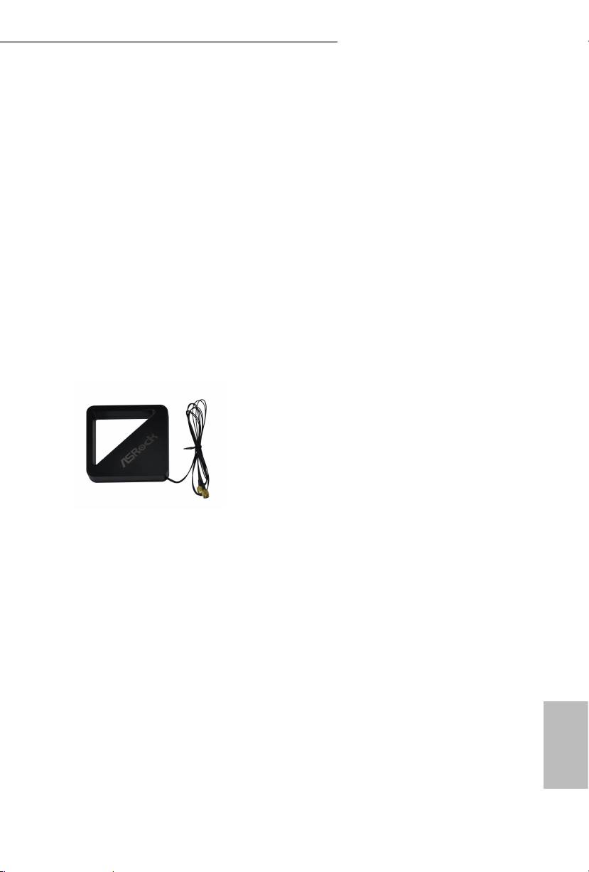
1.4 WiFi-802.11n Module and ASRock WiFi 2.4GHz Antenna
(for Z87 OC Formula/ac only )
WiFi + BT Module
is motherboard comes with an exclusive WiFi 802.11 a/b/g/n/ac + BT v4.0
module that oers support for WiFi 802.11 a/b/g/n/ac connectivity standards and
Bluetooth v4.0. WiFi + BT module is an easy-to-use wireless local area network
(WLAN) adapter to support WiFi + BT. Bluetooth v4.0 standard features Smart
Ready technology that adds a whole new class of functionality into the mobile
devices including Apple’s most recent iPhone 4S. BT 4.0 also includes Low Energy
Technology and ensures extraordinary low power consumption for PCs. e
2T2R WiFi solution sets a WiFi high speed standard and oers max link rate up to
867Mbps.
* e transmission speed may vary according to the environment.
* e WiFi + BT module is supported under Windows® 8 / 8 64-bit / 7 / 7 64-bit
only.
ASRock WiFi 2.4GHz Antenna
English
PB 17
Z87 OC Formula/ac / Z87 OC Formula
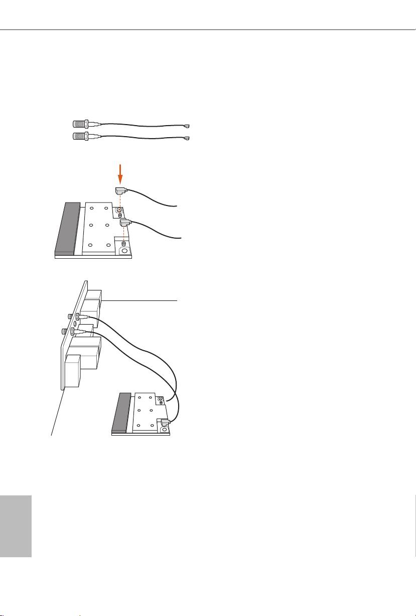
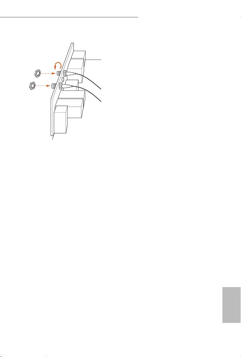
Installing the SMA Wi-Fi Antenna Cables
Step 1
Prepare the SMA Wi-Fi Antenna Cables that
come with the package.
Step 2
Locate the WiFi Module that is installed on the
motherboard's mini-PCIe slot. en attach the
SMA Wi-Fi Antenna Cables to the WiFi Module.
Step3
Insert the RP-SMA Wi-Fi Antenna Connectors
to the antenna ports on the I/O shield
English
18 19
Z87 OC Formula/ac / Z87 OC Formula
Step 4
Fasten the screw nuts to secure the connec-
tors.
English
18 19

Z87 OC Formula/ac / Z87 OC Formula
Chapter 2 Installation
is is an EATX form factor motherboard. Before you install the motherboard,
study the conguration of your chassis to ensure that the motherboard ts into it.
Pre-installation Precautions
Take note of the following precautions before you install motherboard components
or change any motherboard settings.
•
Make sure to unplug the power cord before installing or removing the motherboard.
Failure to do so may cause physical injuries to you and damages to motherboard
components.
•
In order to avoid damage from static electricity to the motherboard’s components,
NEVER place your motherboard directly on a carpet. Also remember to use a grounded
wrist strap or touch a safety grounded object before you handle the components.
•
Hold components by the edges and do not touch the ICs.
•
Whenever you uninstall any components, place them on a grounded anti-static pad or
in the bag that comes with the components.
•
When placing screws to secure the motherboard to the chassis, please do not over-
tighten the screws! Doing so may damage the motherboard.
English
20 21
Z87 OC Formula/ac / Z87 OC Formula
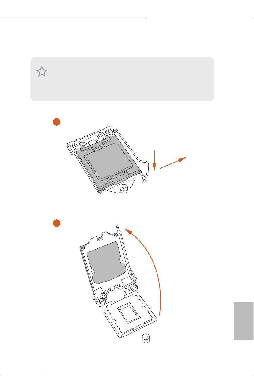
2.1 Installing the CPU
1. Before you insert the 1150-Pin CPU into the socket, please check if the PnP cap is on the
socket, if the CPU surface is unclean, or if there are any bent pins in the socket. Do not
force to insert the CPU into the socket if above situation is found. Otherwise, the CPU
will be seriously damaged.
2. Unplug all power cables before installing the CPU.
1
A
B
2
English
20 21
Z87 OC Formula/ac / Z87 OC Formula
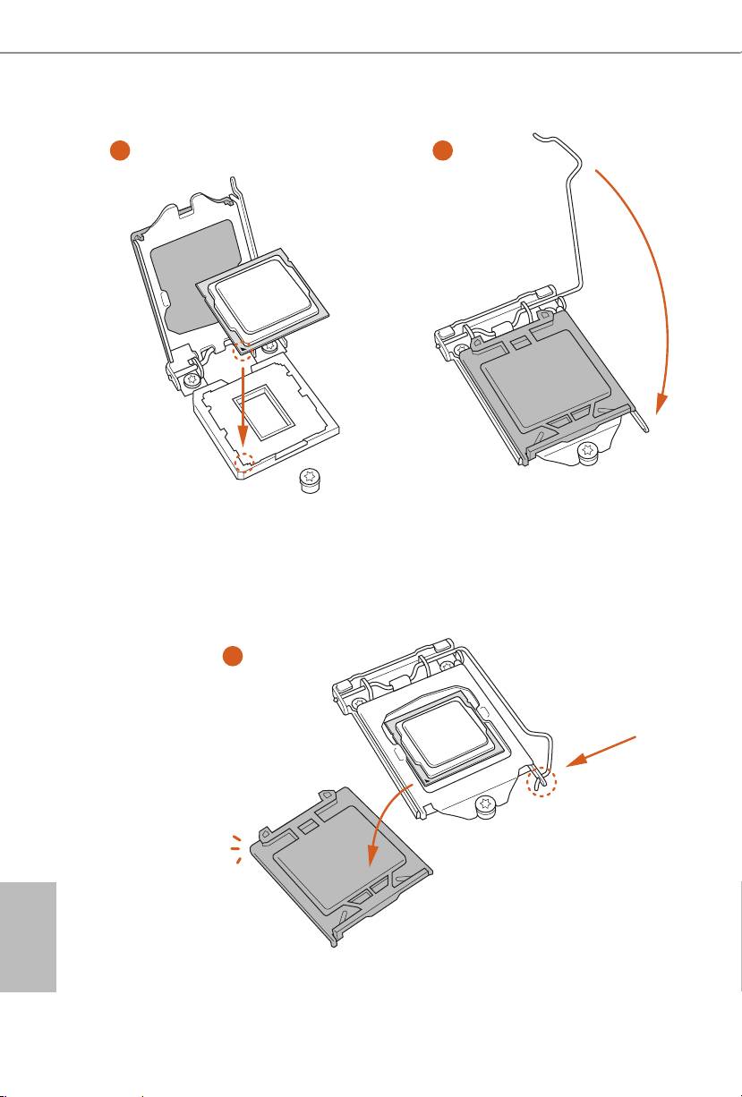
3
4
5
English
22 23

Z87 OC Formula/ac / Z87 OC Formula
Please save and replace the cover if the processor is removed. e cover must be placed if
you wish to return the motherboard for aer service.
English
22 23
Z87 OC Formula/ac / Z87 OC Formula
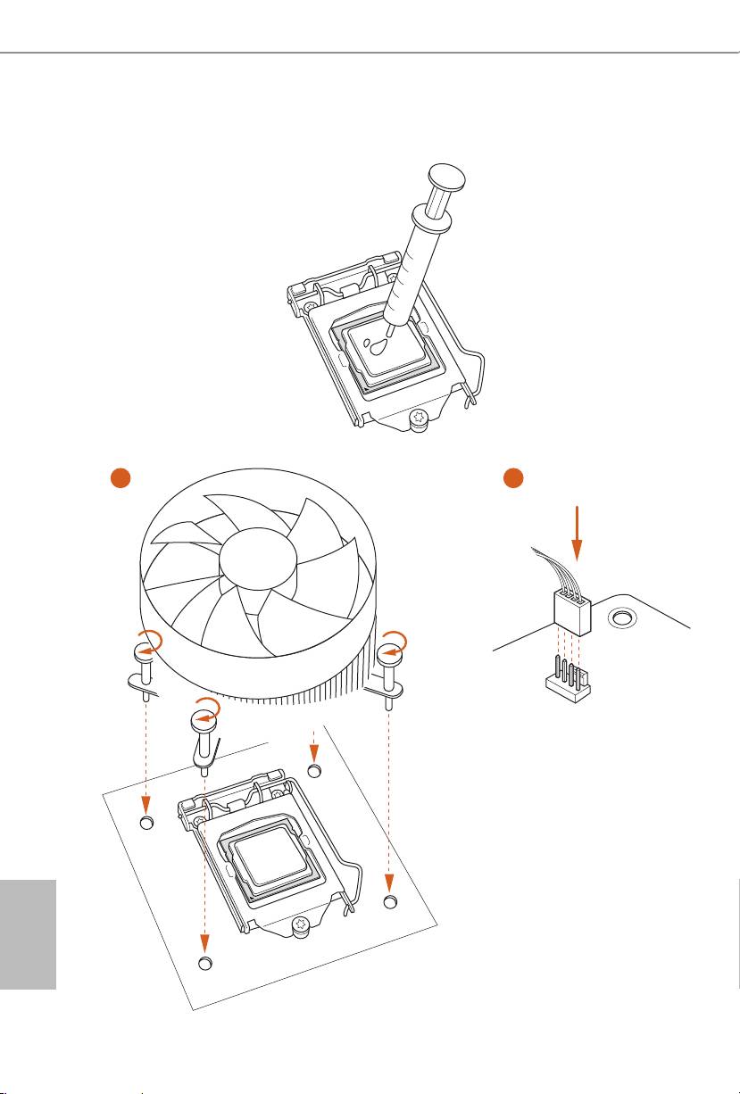
2.2 Installing the CPU Fan and Heatsink
1 2
FAN
CPU_
English
24 25
Z87 OC Formula/ac / Z87 OC Formula
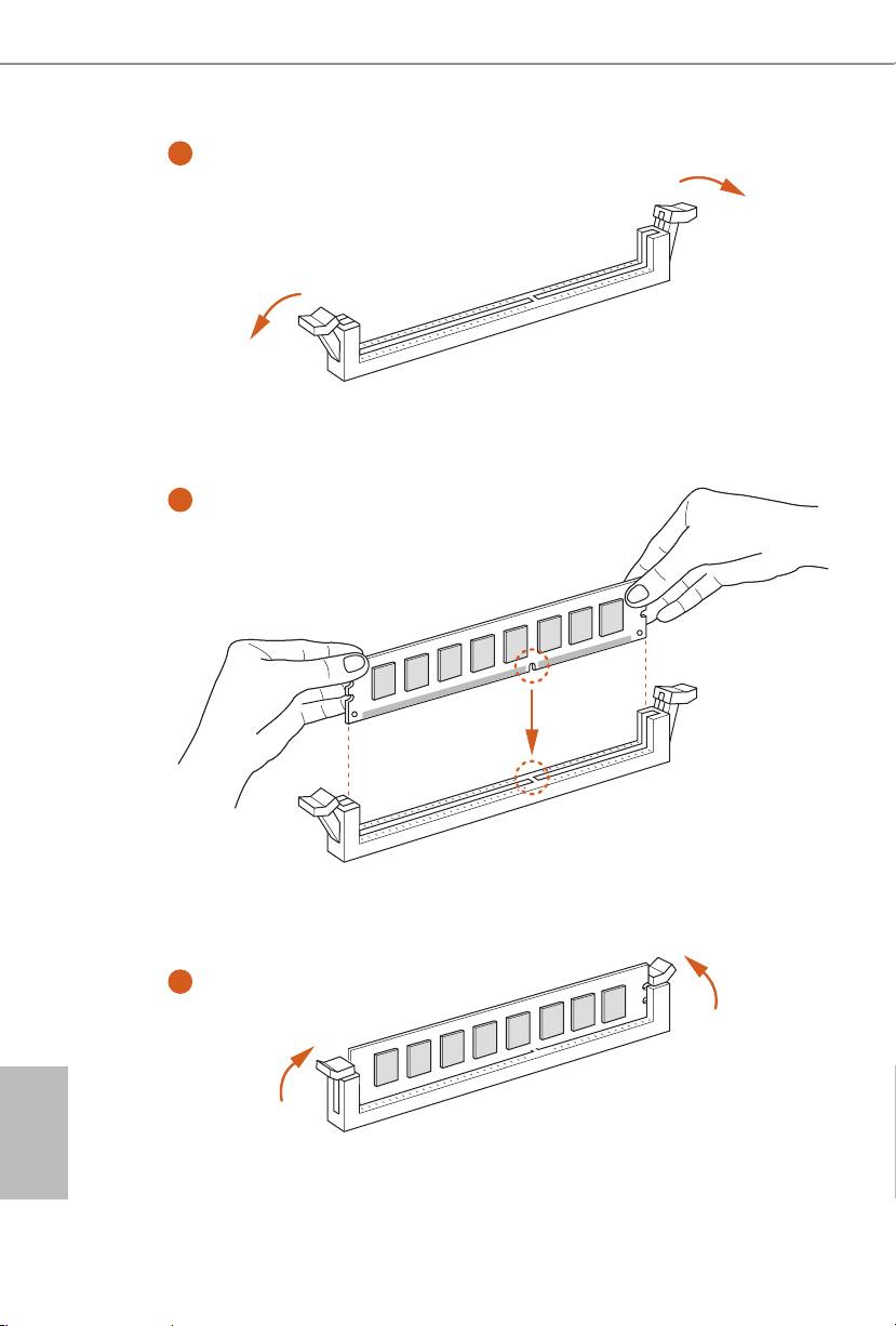
2.3 Installing Memory Modules (DIMM)
is motherboard provides four 240-pin DDR3 (Double Data Rate 3) DIMM slots,
and supports Dual Channel Memory Technology.
1. For dual channel conguration, you always need to install identical (the same brand,
speed, size and chip-type) DDR3 DIMM pairs.
2. It is unable to activate Dual Channel Memory Technology with only one or three memory
module installed.
3. It is not allowed to install a DDR or DDR2 memory module into a DDR3 slot; otherwise,
this motherboard and DIMM may be damaged.
Dual Channel Memory Conguration
Priority DDR3_A1 DDR3_A2 DDR3_B1 DDR3_B2
1 Populated Populated
2 Populated Populated
3 Populated Populated Populated Populated
e DIMM only ts in one correct orientation. It will cause permanent damage to the
motherboard and the DIMM if you force the DIMM into the slot at incorrect orientation.
English
24 25
Z87 OC Formula/ac / Z87 OC Formula
1
2
3
English
26 27

Z87 OC Formula/ac / Z87 OC Formula
2.4 Expansion Slots (PCI and PCI Express Slots)
ere are 6 PCI Express slots and 1 mini-PCI Express slot on the motherboard.
Before installing an expansion card, please make sure that the power supply is switched o
or the power cord is unplugged. Please read the documentation of the expansion card and
make necessary hardware settings for the card before you start the installation.
PCIE slots:
PCIE1 (PCIE 3.0 x16 slot) is used for PCI Express x16 lane width graphics cards.
PCIE2 (PCIE 3.0 x16 slot) is used for PCI Express x8 lane width graphics cards.
PCIE3 (PCIE 2.0 x1 slot) is used for PCI Express x1 lane width cards.
PCIE4 (PCIE 3.0 x16 slot) is used for PCI Express x4 lane width graphics cards.
PCIE5 (PCIE 2.0 x1 slot) is used for PCI Express x1 lane width cards.
PCIE6 (PCIE 2.0 x16 slot) is used for PCI Express x4 lane width graphics cards.
mini-PCIe slots:
MINI_PCIE1 (mini-PCIe slot) is used for WiFi module.
PCIE Slot Congurations
PCIE1 PCIE2 PCIE4 PCIE6
Single Graphics Card x16 N/A N/A N/A
Two Graphics Cards in
x8 N/A x8 N/A
TM
TM
CrossFireX
or SLI
Mode
ree Graphics Cards in
x8 x4 x4 N/A
TM
3-Way CrossFireX
Mode
Four Graphics Cards in
x8 x4 x4 x4
TM
4-Way CrossFireX
Mode
For a better thermal environment, please connect a chassis fan to the motherboard’s chas-
sis fan connector (CHA_FAN1, CHA_FAN2, CHA_FAN3 or CHA_FAN4) when using
multiple graphics cards.
English
26 27
Z87 OC Formula/ac / Z87 OC Formula
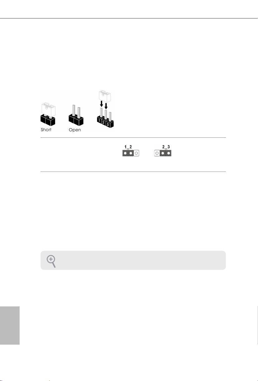
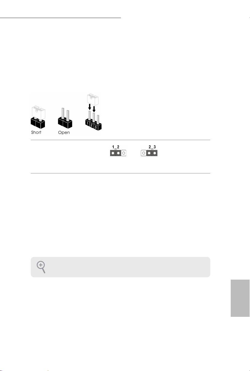
2.5 Jumpers Setup
e illustration shows how jumpers are setup. When the jumper cap is placed on
the pins, the jumper is “Short”. If no jumper cap is placed on the pins, the jumper
is “Open”. e illustration shows a 3-pin jumper whose pin1 and pin2 are “Short”
when a jumper cap is placed on these 2 pins.
Clear CMOS Jumper
(CLRCMOS1)
Clear CMOSDefault
(see p.1 or 2, No. 35)
CLRCMOS1 allows you to clear the data in CMOS. To clear and reset the system
parameters to default setup, please turn o the computer and unplug the power
cord from the power supply. Aer waiting for 15 seconds, use a jumper cap to
short pin2 and pin3 on CLRCMOS1 for 5 seconds. However, please do not clear
the CMOS right aer you update the BIOS. If you need to clear the CMOS when
you just nish updating the BIOS, you must boot up the system rst, and then shut
it down before you do the clear-CMOS action. Please be noted that the password,
date, time, and user default prole will be cleared only if the CMOS battery is
removed.
e Clear CMOS Switch has the same function as the Clear CMOS jumper.
English
28 29
Z87 OC Formula/ac / Z87 OC Formula
2.6 Onboard Headers and Connectors
Onboard headers and connectors are NOT jumpers. Do NOT place jumper caps over these
headers and connectors. Placing jumper caps over the headers and connectors will cause
permanent damage to the motherboard.
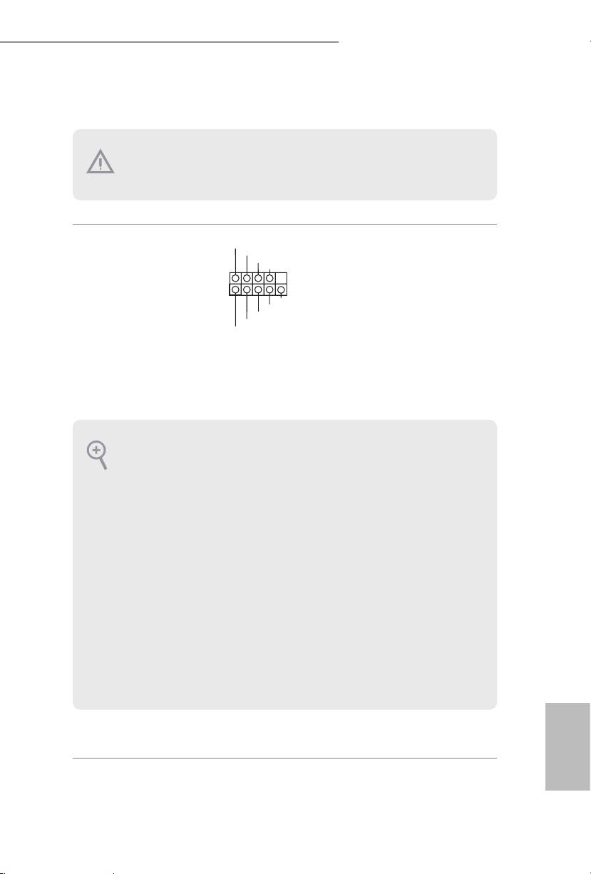
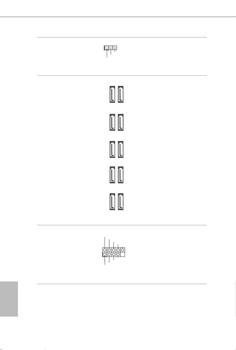
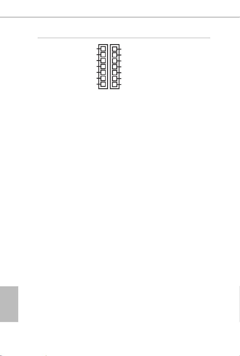
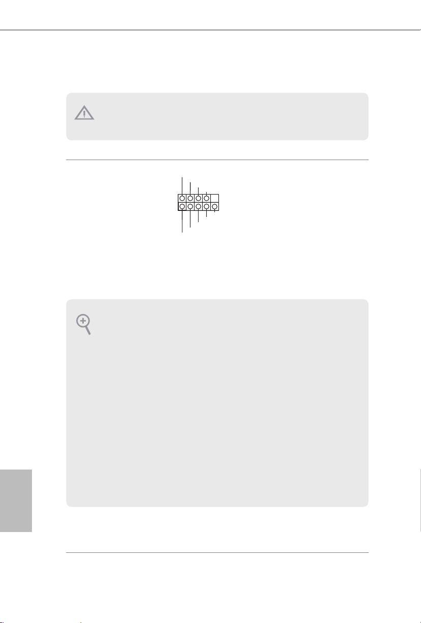
PLED+
System Panel Header
Connect the power
PLED-
PWRBTN#
(9-pin PANEL1)
GND
switch, reset switch and
(see p.1 or 2, No. 27)
system status indicator on
1
GND
the chassis to this header
R ESET#
GND
according to the pin
HDLED-
HDLED+
assignments below. Note
the positive and negative
pins before connecting
the cables.
PWRBTN (Power Switch):
Connect to the power switch on the chassis front panel. You may congure the way to turn
o your system using the power switch.
RESET (Reset Switch):
Connect to the reset switch on the chassis front panel. Press the reset switch to restart the
computer if the computer freezes and fails to perform a normal restart.
PLED (System Power LED):
Connect to the power status indicator on the chassis front panel. e LED is on when the
system is operating. e LED keeps blinking when the system is in S1/S3 sleep state. e
LED is o when the system is in S4 sleep state or powered o (S5).
HDLED (Hard Drive Activity LED):
Connect to the hard drive activity LED on the chassis front panel. e LED is on when the
hard drive is reading or writing data.
e front panel design may dier by chassis. A front panel module mainly consists of power
switch, reset switch, power LED, hard drive activity LED, speaker and etc. When connect-
ing your chassis front panel module to this header, make sure the wire assignments and the
pin assignments are matched correctly.
English
28 29
Z87 OC Formula/ac / Z87 OC Formula
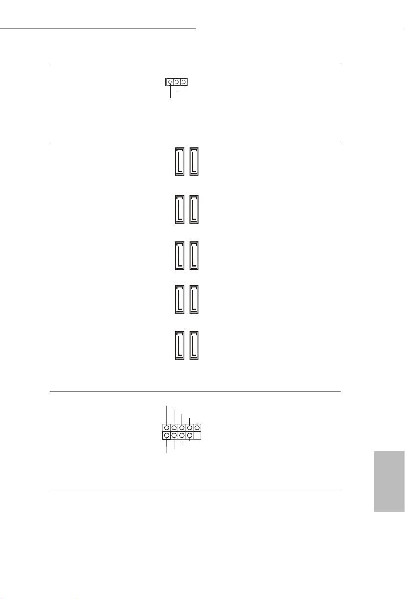
Power LED Header
Please connect the chassis
(3-pin PLED1)
power LED to this header
(see p.12, No. 17)
to
indicate the system’s
power status.
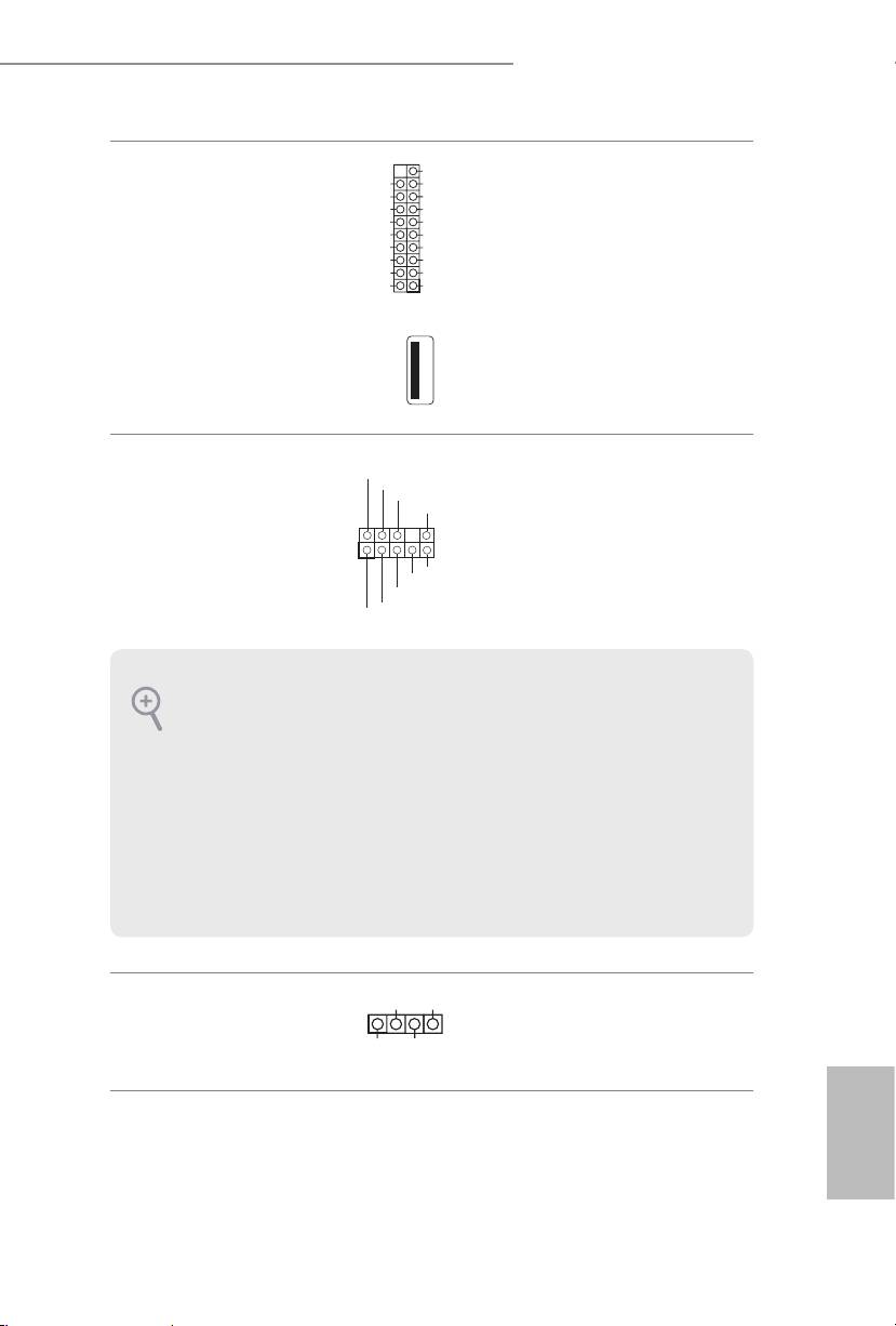
Serial ATA3 Connectors
ese ten SATA3
(SATA3_0_1:
connectors support SATA
see p.1 or 2, No. 22)
data cables for internal
(SATA1_2_3:
storage devices with up to
see p.1 or 2, No. 23)
6.0 Gb/s data transfer rate.
(SATA3_4_5:
To minimize the boot
see p.1 or 2, No. 24)
time, use Intel® Z87 SATA
(SATA3_A1_A2:
ports (SATA3_0) for your
see p.1 or 2, No. 21)
bootable devices.
(SATA3_A3_A4:
see p.1 or 2, No. 20)
USB 2.0 Headers
Besides two USB 2.0 ports
(9-pin USB2_3)
on the I/O panel, there
(see p.1 or 2, No. 33)
are two headers on this
(9-pin USB4_5)
motherboard. Each USB
(see p.1 or 2, No. 36)
2.0 header can support
two ports.
English
30 31
1
PLED-
PLED+
PLED+
SATA3_0_1 SATA3_4_5SATA3_2_3
SATA3_A3_A4 SATA3_A1_A2
USB_PWR
P-
P+
GND
DUMMY
1
GND
P+
P-
USB_PWR
Z87 OC Formula/ac / Z87 OC Formula
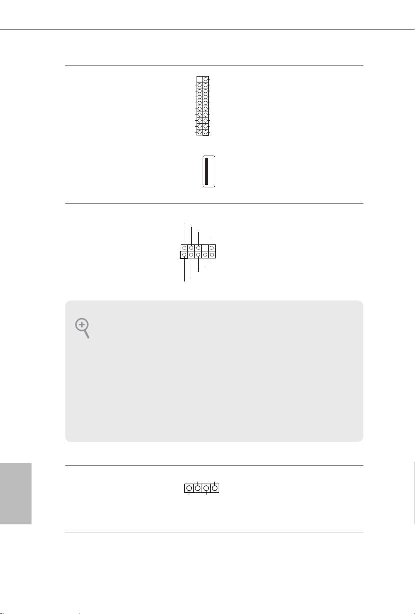
USB 3.0 Headers
Besides four USB 3.0 ports
(19-pin USB3_8_9)
on the I/O panel, there
(see p.1 or 2, No. 15)
are two headers and one
(19-pin USB3_10_11)
port on this motherboard.
(see p.1 or 2, No. 16)
Each USB 3.0 header can
support two ports.
(USB3_12)
(see p.1 or 2, No. 13)
Front Panel Audio Header
is header is for
(9-pin HD_AUDIO1)
connecting audio devices
(see p.1 or 2, No. 40)
to the front audio panel.
Chassis Speaker Header
Please connect the chassis
(4-pin SPEAKER1)
speaker to this header.
(see p.1 or 2, No. 25)
English
30 31
1
VbusVbus
Vbus
IntA_PB_SSRX-
IntA_PA_SSRX-
IntA_PB_SSRX+
IntA_PA_SSRX+
GND
GND
IntA_PB_SSTX-
IntA_PA_SSTX-
IntA_PB_SSTX+
IntA_PA_SSTX+
GND
GND
IntA_PB_D-
IntA_PA_D-
IntA_PB_D+
IntA_PA_D+
Dummy
GND
PRESENCE#
MIC_RET
OUT_RET
1
OUT2_L
J_SENSE
OUT2_R
MIC2_R
MIC2_L
1. High Denition Audio supports Jack Sensing, but the panel wire on the chassis must sup-
port HDA to function correctly. Please follow the instructions in our manual and chassis
manual to install your system.
2. If you use an AC’97 audio panel, please install it to the front panel audio header by the
steps below:
A. Connect Mic_IN (MIC) to MIC2_L.
B. Connect Audio_R (RIN) to OUT2_R and Audio_L (LIN) to OUT2_L.
C. Connect Ground (GND) to Ground (GND).
D. MIC_RET and OUT_RET are for the HD audio panel only. You don’t need to connect
them for the AC’97 audio panel.
E. To activate the front mic, go to the “FrontMic” Tab in the Realtek Control panel and
adjust “Recording Volume”.
1
+5V
DUMMY
DUMMY
SPEAKER
Z87 OC Formula/ac / Z87 OC Formula
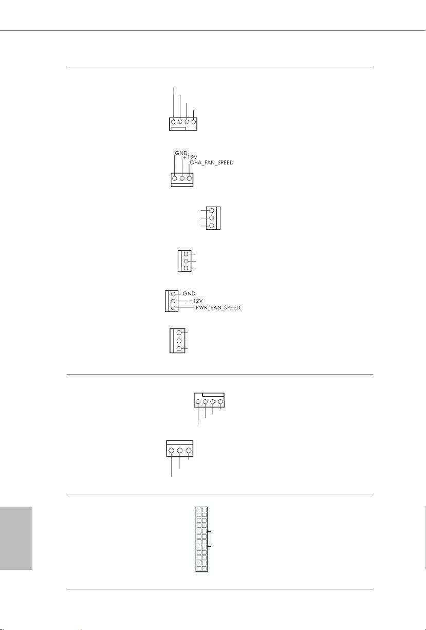
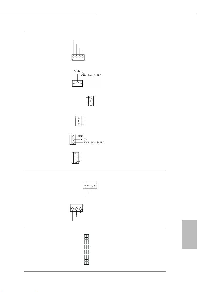
Chassis, Power and MOS
Please connect fan cables
Fan Connectors
to the fan connectors and
(4-pin CHA_FAN1)
match the black wire to
(see p.1 or 2, No. 37)
the ground pin.
(3-pin CHA_FAN2)
(see p.1 or 2, No. 34)
(3-pin CHA_FAN3)
(see p.1 or 2, No. 19)
(3-pin CHA_FAN4)
(see p.1 or 2, No. 42)
(3-pin PWR _FAN1)
(see p.1 or 2, No. 41)
(3-pin MOS_FAN1)
(see p.1 or 2, No. 43)
CPU Fan Connectors
is motherboard pro-
(4-pin CPU_FAN1)
vides a 4-Pin CPU fan
(see p.1 or 2, No. 3)
(Quiet Fan) connector.
If you plan to connect a
3-Pin CPU fan, please
(3-pin CPU_FAN2)
connect it to Pin 1-3.
(see p.1 or 2, No. 4)
ATX Power Connector
is motherboard pro-
English
(24-pin ATXPWR1)
vides a 24-pin ATX power
(see p.1 or 2, No. 12)
connector. To use a 20-pin
ATX power supply, please
plug it along Pin 1 and Pin
13.
32 33
GND
+12V
CHA_FAN_SPEED
FAN_SPEED_CONTR
OL
GND
+ 12V
CHA_ FA
N_SPEED
GND
+12V
MOS_FAN_SPEED
GND
+
12V
FAN_SPEED
GND
+12V
CPU_FAN_SPEED
GN D
+12V
CPU_FA
N_SPEED
FA
4 3 2 1
N_SPEED_CONTROL
12
24
1
13
Z87 OC Formula/ac / Z87 OC Formula
English
32 33
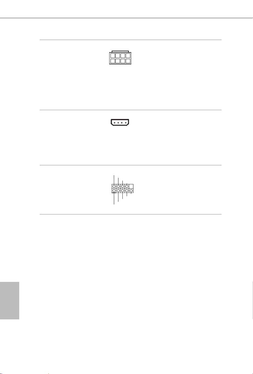
4
1
8
ATX 12V Power
5
is motherboard pro-
Connector
vides an 8-pin ATX 12V
(8-pin ATX12V1)
power connector. To use a
(see p.1 or 2, No. 1)
4-pin ATX power supply,
(8-pin ATX12V3)
please plug it along Pin 1
(see p.1 or 2, No. 2)
and Pin 5.
SLI/XFIRE Power
Please connect this
Connector
connector with a hard
(4-pin SLI/XFIRE_
disk power connector
PWR1)
when two graphics cards
(see p.1 or 2, No. 39)
are installed on this
motherboard.
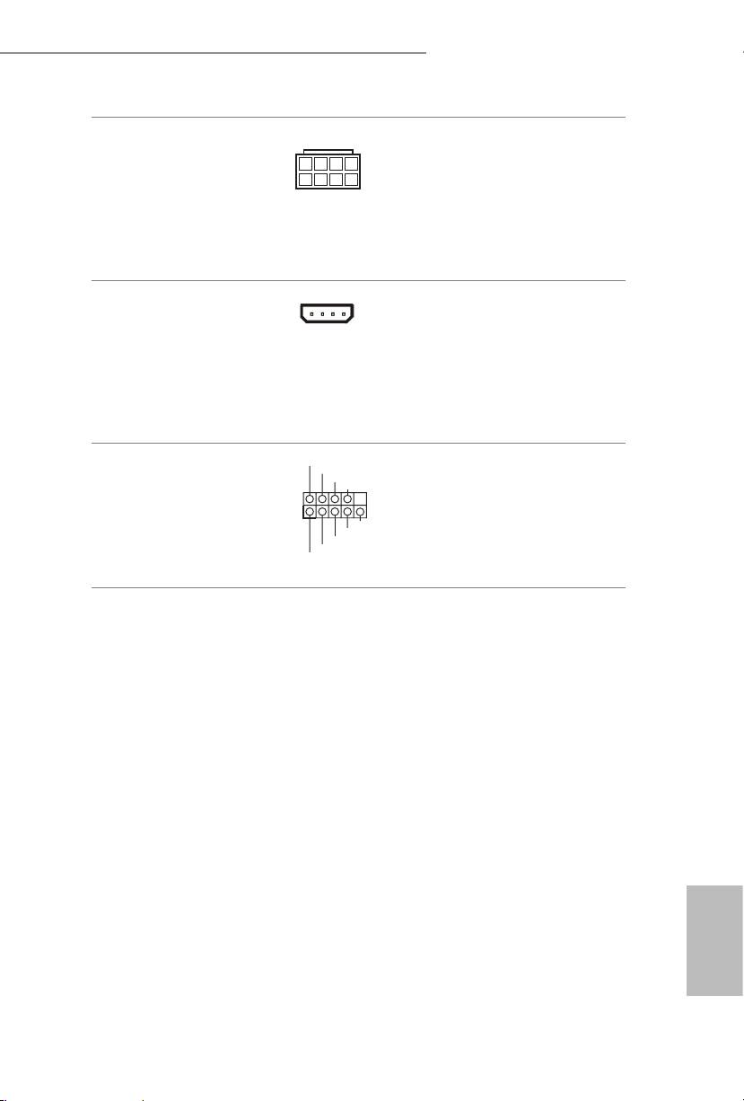
RRXD1
Serial Port Header
DDTR#1
is COM1 header
DDSR#1
CCTS#1
(9-pin COM1)
supports a serial port
(see p.1 or 2, No. 38)
module.
RRTS#1
GND
TTXD1
DDCD#1
1
RRI#1
Z87 OC Formula/ac / Z87 OC Formula
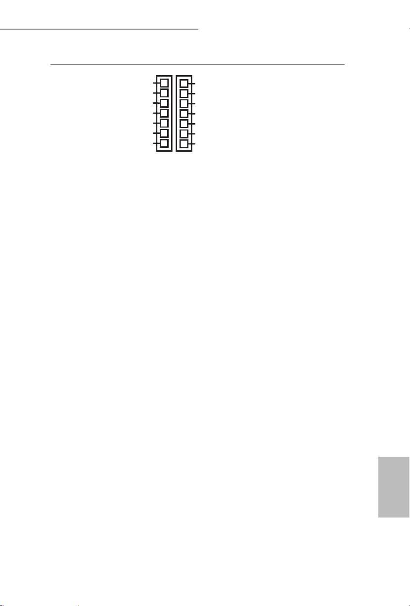
TM
V-Probe
Users are able to measure
IO
PCH_IREF
GFX
VCOMP2
onboard components
(7-pin VOL_
SA
1.5VPCH
voltage.
CON1, 7-pin VOL_
RING
1.05PCH
CON2)
PCH_IREF:
VCOMP
VCCM
(see p.1 or 2, No.
CORE0
VCCin
PCH1.5V IREF voltage
11)
GND
GND
VCOMP2:
CPU 2nd COMP voltage
1.5VPCH:
PCH 1.5V voltage
1.05PCH:
PCH 1.05V voltage
VCCM:
DRAM voltage
VCC-in
:
CPU input voltage
IO:
CPU IO voltage
GFX:
CPU GFX (Graphics)
voltage
SA:
CPU system agent voltage
RING:
CPU Ring (cache) voltage
VCOMP:
CPU COMP voltage
CORE0:
CPU CORE0 voltage
English
34 35
Z87 OC Formula/ac / Z87 OC Formula
2.7 Smart Switches
e motherboard has three smart switches: Power Switch, Reset Switch and Clear
CMOS Switch, allowing users to quickly turn on/o the system, reset the system or
clear the CMOS values.
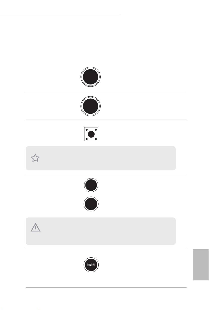
Power Switch
Power Switch allows users to
Power
(PWRBTN)
quickly turn on/o the system.
(see p.1 or 2, No. 28)
Reset Switch
Reset Switch allows users to
(RSTBTN)
Reset
quickly reset the system.
(see p.1 or 2, No. 29)
Clear CMOS Switch
Clear CMOS Switch allows
(CLRCBTN)
users to quickly clear the
(see p.1 or 2, No. 30)
CMOS values.
is function is workable only when you power o your computer and unplug the power
supply.
+ / - Rapid OC
+ / - Rapid OC Buttons allow
Buttons
users to quickly and easily
(MINUS1: see p.1 or
adjust OC frequency in Rapid
2, No. 7)
OC.
(PLUS1: see p.1 or 2,
No. 8)
Menu Button
MENU Button allow users to
(MENU1: see p.1 or 2,
quickly toogle among Date/
No. 9)
Time, Temperature, and Volt-
English
age information shown on
Status OLED.
34 35
+
-
is overclocking behavior depends on the system conguration, such as memory capabil-
ity, thermal solution, etc. Overclocking may aect your system stability, or even cause dam-
age to the components and devices. We are not responsible for possible damage caused by
overclocking.
MENU
Z87 OC Formula/ac / Z87 OC Formula
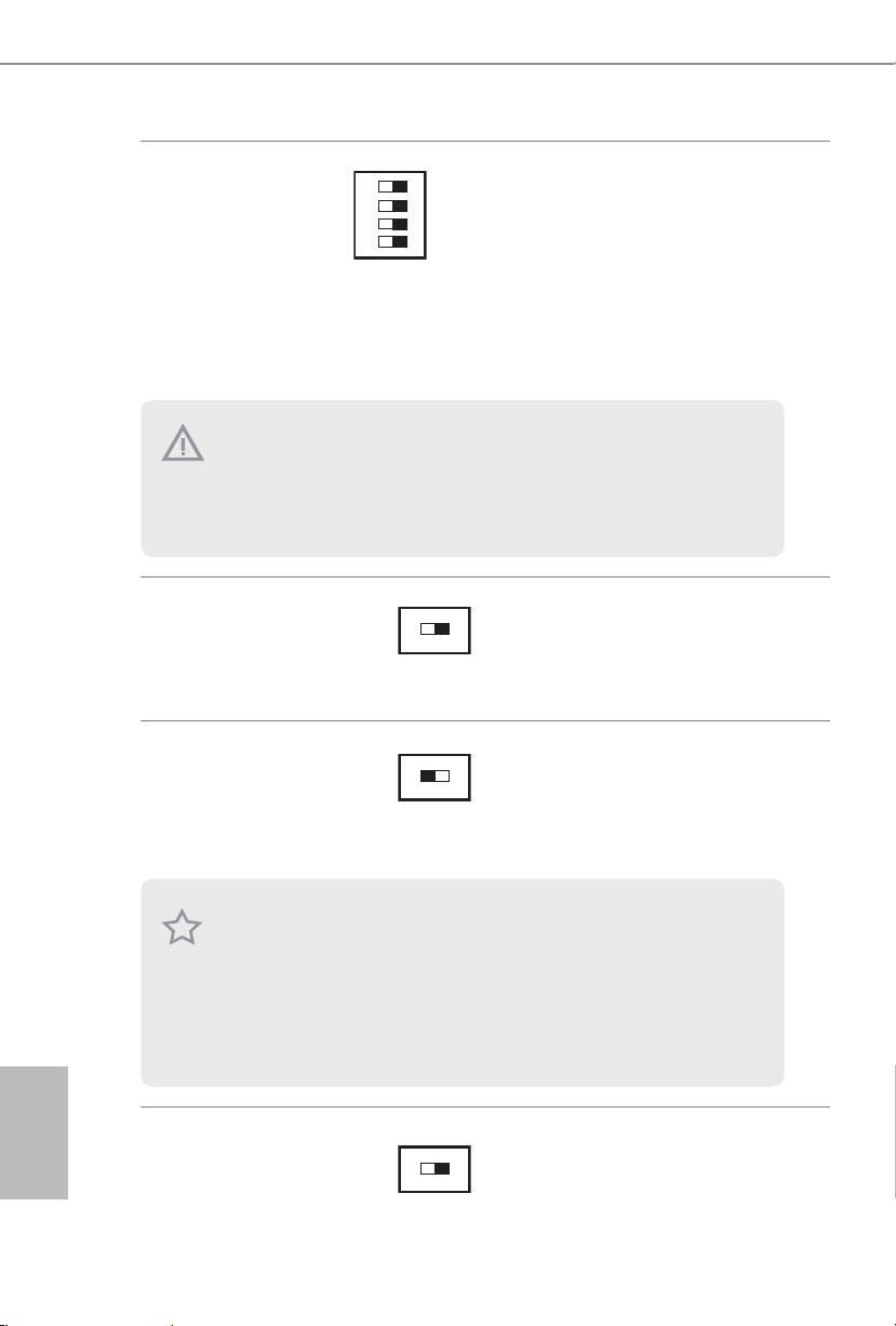
PCIe ON/OFF
1 2 3 4
ON
1: PCIE1
PCIe ON/OFF Switch allows
Switch
2: PCIE2
you to enable and disable the
(SWITCH1)
3: PCIE4
corresponding PCIE x16 slots.
(see p.1 or 2 No. 14)
4: PCIE6
When one of the installed
PCIE x16 cards is out of order,
you can use PCIe ON/OFF
Switch to nd out the faulty
one just with a single click
without removing the cards.
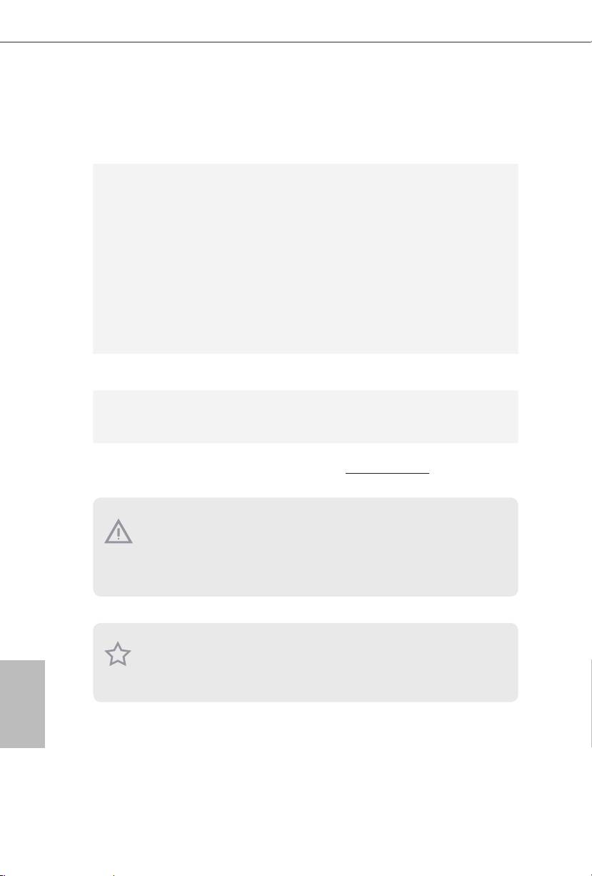
Slow Mode Switch
OFF
ON
If Slow Mode is on, the proces-
(SLOWMODE1)
sor runs at lowest frequency.
(see p.1 or 2 No. 17)
BIOS Selection
BIOS Selection Switch allows
Switch
the system to boot from either
(BIOS_SEL1)
BIOS A or BIOS B.
(see p.1 or 2 No. 32)
English
LN2 Mode Switch
e LN2 mode aids in
OFF
ON
(LN2MODE1)
eliminating the cold-boot bug
(see p.1 or 2, No. 18)
issues in processors during
extreme overclocking with
Liquid Nitrogen.
36 PB
AB
1. Make sure that you power o the system before changing the switch.
2. When you turn o PCIe ON/OFF switch, your PCIE card could be burnt if it was poorly
designed. For more information about your card’s specications please contact the card’s
vendor.
3. PCIe ON/OFF switch is for debug only. If you do not want to use your PCIE card, please
remove it from the motherboard.
is motherboard has two BIOS chips, a primary BIOS (BIOS_A) and a backup BIOS (BIOS_
B), which enhances the safety and stability of your system. Normally, the system will work
on the primary BIOS. However, if the primary BIOS is corrupted or damaged, just ip the
BIOS Selection Switch to “B”, then the backup BIOS will take over on the next system boot.
Aer that, use “Secure Backup UEFI” in the UEFI Setup Utility to duplicate a working copy
of the BIOS les to the primary BIOS to ensure normal system operation. For safety issues,
users are not able to update the backup BIOS manually. Users may refer to the BIOS LEDs
(BIOS_A_LED or BIOS_B_LED) to identify which BIOS is currently activated.

Z87 OC Formula/ac / Z87 OC Formula
1 Einleitung
Vielen Dank, dass Sie sich für das Z87 OC Formula/ac / Z87 OC Formula von ASRock
entschieden haben – ein zuverlässiges Motherboard, das konsequent unter der
strengen Qualitätskontrolle von ASRock hergestellt wurde. Es liefert ausgezeichnete
Leistung mit robustem Design, das ASRocks Streben nach Qualität und Beständigkeit
erfüllt.
Da die technischen Daten des Motherboards sowie die BIOS-Soware aktualisiert werden
können, kann der Inhalt dieser Dokumentation ohne Ankündigung geändert werden. Falls
diese Dokumentation irgendwelchen Änderungen unterliegt, wird die aktualisierte Version
ohne weitere Hinweise auf der ASRock-Webseite zur Verfügung gestellt. Sollten Sie technische
Hilfe in Bezug auf dieses Motherboard benötigen, erhalten Sie auf unserer Webseite spezischen
Informationen über das von Ihnen verwendete Modell. Auch nden Sie eine aktuelle Liste
unterstützter VGA-Karten und Prozessoren auf der ASRock-Webseite: ASRock-Website
http://www.asrock.com.
1.1 Lieferumfang
• ASRock Z87 OC Formula/ac- / Z87 OC Formula-Motherboard (EATX-Formfaktor)
• ASRock Z87 OC Formula/ac- / Z87 OC Formula-Schnellinstallationsanleitung
• ASRock Z87 OC Formula/ac- / Z87 OC Formula-Support-CD
• 10 x Serial-ATA- (SATA) Datenkabel (optional)
• 2 x SATA-1:1-Netzkabel (optional)
• 1 x E/A-Blendenabschirmung
• 1 x Flexibles ASRock-SLI-Bridge-Anschlusskabel
• 1 x Vordere USB 3.0-Blende mit 2,5-Zoll-HDD/SSD-Rack
• 4 x HDD-Schrauben
• 6 x Gehäuseschrauben
• 1 x Hintere USB 3.0-Halterung
• 10 x Übertaktungsständer
• GC-Extreme-Wärmeleitpaste von GELID Solutions
• 1 x ASRock-2,4/5-GHz-WLAN-Antenne (nur beim Z87 OC Formula/ac)
• 2 x SMA-WLAN-Antennenkabel (nur beim Z87 OC Formula/ac)
• 1 x WLAN-Modulschraube (nur beim Z87 OC Formula)
Deutsch
37

1.2 Technische Daten
Plattform
• EATX-Formfaktor (12,0 Zoll x 10,5 Zoll, 30,5 cm x 26,7 cm)
• Premium Gold-Kondensatordesign (100 % in Japan gefertigt,
hochqualitative leitfähige Polymer-Kondensatoren)
A-Stil
• Home Cloud
• Gleichmäßiger Überzug
TM
• Purity Sound
• 802.11ac Wi-Fi (nur beim Z87 OC Formula/ac)
• HDMI-Eingang
OC Formula-
OC Formula-Stromversorgungskit
Kit
• 12-Leistungsphasendesign
• Digipower
• Dual-Stack-MOSFET (DSM)
• Multiple Filter Cap (MFC) (Filterung verschiedener
Störsignale durch drei verschiedene Kondensatoren: DIP-
Feststoondensator, POSCAP und MLCC)
• Erstklassiger Legierungsdrossel (reduziert Kernverlust im
Vergleich zu Eisenpulverdrossel um 70 %)
OC Formula-Anschlusskit
• Hi-Density-Netzanschluss (8-polig)
• 15μGold Finger (CPU-Sockel, Speichersockel und PCIE-x16-
Steckplätze)
• Verzerrungsfreier Steckplatz
OC Formula-Kühlkit
• Twin-Power-Cooling (kombiniert aktive Lukühlung und
Wasserkühlung)
• 8-Layer-PCB
• 4 x 2-oz-Kupfer
• GC-Extreme-Wärmeleitpaste von GELID Solutions
OC Formula-Monitorkit
Deutsch
• Status-OLED
• Multiwärmesensor
Prozessor
• Unterstützt Intel® CoreTM i7 / i5 / i3 / Xeon® / Pentium® /
Celeron® der 4. Generation im LGA1150-Paket
• 12-Leistungsphasendesign
• Unterstützt Intel® Turbo Boost 2.0-Technologie
• Unterstützt CPU mit freiem Multiplikator der Intel® K-Serie
38
• Unterstützt ASRock BCLK-Übertaktung (voller Bereich)

Z87 OC Formula/ac / Z87 OC Formula
®
Chipsatz
• Intel
Z87
Speicher
• Dualkanal-DDR3-Speichertechnologie
• 4 x DDR3-DIMM-Steckplätze
• Unterstützt DDR3 3000+(OC)/2933(OC)/2800(OC)/
2400(OC)/2133(OC)/1866(OC)/1600/1333/1066 non-ECC,
ungepuerter Speicher
• Systemspeicher, max. Kapazität: 32GB
• Unterstützt Intel® Extreme Memory Prole (XMP)1.3/1.2
• Verzerrungsfreier Steckplatz
Erweiter-
• 3 x PCI-Express 3.0-x16-Steckplätze (PCIE1/PCIE2/
ungssteck-
PCIE4:einzeln bei x16 (PCIE1); doppelt bei x8 (PCIE1) / x8
platz
(PCIE2); dreifach bei x8 (PCIE1) / x4 (PCIE2) / x4 (PCIE4))
• 1 x PCI-Express 2.0-x16-Steckplatz (PCIE6:x4-Modus)
• 2 x PCI-Express 2.0-x1-Steckplätze
• 1 x Mini-PCI-Express-Steckplatz: Für WiFi- + BT-Modul*Mini-
PCI-Express-Steckplatz mit PCIE5-Steckplatz geteilt
• PLX8605-integriert
TM
TM
• Unterstützt AMD Quad CrossFireX
, 4-Wege-CrossFireX
,
TM
TM
3-Wege-CrossFireX
und CrossFireX
TM
TM
• Unterstützt NVIDIA® Quad SLI
und SLI
Grakkarte
• Integrierte Intel® HD Graphics-Visualisierung und VGA-
Ausgänge können nur mit Prozessoren unterstützt werden, die
GPU-integriert sind.
• Unterstützt integrierte Intel® HD Graphics-Visualisierung:
Intel® Quick Sync Video mit AVC, MVC (S3D) und MPEG-
TM
2 Full HW Encode1, Intel® InTru
3D, Intel® Clear Video HD
TM
Technology, Intel® Insider
, Intel® HD Graphics 4400/4600
• Pixel Shader 5.0, DirectX 11.1
• Max. geteilter Speicher: 1792 MB
• Unterstützt HDMI-Technologie mit maximaler Auösung von
4K × 2K (4096 x 2304) bei 24 Hz
• Unterstützt Auto-Lippensynchronizität, hohe Farbtiefe (12
bpc), xvYCC und HBR (Audio mit hoher Bitrate) mit HDMI
Deutsch
(konformer HDMI-Monitor erforderlich)
• Unterstützt HDCP-Funktion mit HDMI-Port
• Unterstützt Blu-ray- (BD) Wiedergabe (Full HD/1080p) mit
HDMI-Port
39

Audio
• 7.1-Kanal-HD-Audio mit Inhaltsschutz (Realtek ALC1150-
Audiocodec)
• Erstklassige Blu-ray-Audiounterstützung
• Unterstützt Purity Sound™
- 115-dB-SRV-DAC mit Dierentialverstärker
- TI® NE5532 erstklassiger Headset
-Verstärker (unterstützt Headsets mit bis zu 600 Ohm)
- Direct Drive Technology
- Abdeckung mit EMV-Abschirmung
- PCB-isolierte Abschirmung
• Unterstützt DTS Connect
LAN
• Gigabit LAN 10/100/1000 Mb/s
• Giga PHY Intel® I217V
• Unterstützt Intel® Remote Wake Technology
• Unterstützt Wake-On-LAN
• Unterstützt energieezientes Ethernet 802.3az
• Unterstützt PXE
Rückblende,
• 1 x PS/2-Maus-/Tastaturanschluss
E/A
• 1 x HDMI-Ausgang
• 1 x HDMI-Eingang
• 1 x Optischer SPDIF-Ausgang
• 2 x USB 2.0-Ports
• 4 x USB 3.0-Ports (Intel Z87)
* USB3_10_11 mit PCIE6 geteilt. Falls der PCIE6-Steckplatz belegt
ist, wechselt USB3_10_11 zu USB 2.0.
• 4 x USB 3.0-Ports (Etron EJ188H)
• 1 x RJ-45-LAN-Port mit LED (Aktivität/Verbindung-LED und
Geschwindigkeit-LED)
• 1 x CMOS-löschen-Taste
• HD-Audioanschluss: Hintere Lautsprecher / Zentral / Bass /
Line-in / Vorderer Lautsprecher / Mikrofon
Deutsch
40

Z87 OC Formula/ac / Z87 OC Formula
Speicher
• 6 x SATA-III-6,0-Gb/s-Anschlüsse über Intel® Z87, unterstützt
RAID (RAID 0, RAID 1, RAID 5, RAID 10, Intel Rapid Storage
Technology 12 und Intel Smart Response Technology), NCQ,
AHCI und „Hot-Plugging“-Funktionen
• 4 x SATA-III-6,0-Gb/s-Anschlüsse von ASMedia ASM1061,
unterstützt NCQ, AHCI und „Hot-Plugging“-Funktionen
Anschluss
• 1 x COM-Anschluss-Stileiste
• 1 x Betrieb-LED-Stileiste
• 2 x CPU-Lüeranschlüsse (1 x 4-polig, 1 x 3-polig)
• 4 x Gehäuselüeranschlüsse (1 x 4-polig, 3 x 3-polig)
• 1 x Netzteillüeranschluss (3-polig)
• 1 x MOS-Lüeranschluss (3-polig)
• 1 x 24-poliger ATX-Netzanschluss
• 2 x 8-poliger 12-V-Netzanschlüsse (hochdichter Netzanschluss)
• 1 x SLI/XFire-Netzanschluss
• 1 x Audioanschluss an Frontblende
• 2 x USB 2.0-Stileisten (unterstützt sechs USB 2.0-Ports)
• 1 x Vertikal, Typ A, USB 3.0
• 2 x USB 3.0-Stileisten (unterstützt vier USB 3.0-Ports)
• 1 x Ein-/Austaste mit LED
• 1 x Reset-Taste mit LED
• 1 x CMOS-löschen-Schalter
TM
• V-Probe
: 2 x 7-teilige Spannungsmesspunkte auf Platine
• Schnellübertaktungstaste: Tasten +/- zur Anpassung der
Übertaktungsfrequenz
• 1 x PCIe-Ein-/Ausschalter
• 1 x Post Status Checker (PSC)
• 1 x Langsamer-Modus-Schalter
• 1 x LN2-Modus-Schalter
• 1 x BIOS-Auswahlschalter
BIOS-Funktion
• 2 x 64-Mb-AMI-UEFI-Legal-BIOS mit Unterstützung
mehrsprachiger grascher Benutzerschnittstellen (1 x Haupt-
BIOS und 1 x Ausfall-BIOS)
• Unterstützt UEFI-Technologie (zuverlässige Sicherung)
Deutsch
• ACPI 1.1-konforme Aufweckereignisse
• SMBIOS 2.3.1-Unterstützung
• CPU, DRAM, PCH 1,05 V, PCH 1,5 V /
Mehrfachspannungsanpassung
41
Support-CD
• Treiber, Dienstprogramme, Antivirensoware (Testversion),
CyberLink MediaEspresso 6.5-Testversion, Google Chrome
Browser und Toolbar, Start8, MeshCentral, Splashtop Streamer
Hardware-
• CPU/Gehäuse/Netzteil/MOS-Temperaturerkennung
• CPU/Gehäuse/Netzteil/MOS-Lüertachometer
• Lautloser CPU/Gehäuse/MOS-Lüer (ermöglicht automatische
Anpassung der Geschwindigkeit des Gehäuselüers über die
CPU-Temperatur)
• CPU/Gehäuse/MOS-Lüer-Mehrfachgeschwindigkeitssteueru
ng
• Multiwärmesensor
• Spannungsüberwachung: +12 V, +5 V, +3,3 V, CPU Vcore
• 1 x Status-OLED
Betriebssystem
• Konform mit Microso® Windows® 8 / 8, 64 Bit / 7 / 7, 64 Bit
Zertizierungen
• FCC, CE, WHQL
• ErP/EuP ready (ErP/EuP ready-Netzteil erforderlich)
* Detaillierte Produktinformationen nden Sie auf unserer Webseite: http://www.asrock.com
Bitte beachten Sie, dass mit einer Übertaktung, zu der die Anpassung von BIOS-
Einstellungen, die Anwendung der Untied Overclocking Technology oder die Nutzung von
Übertaktungswerkzeugen von Drittanbietern zählen, bestimmte Risiken verbunden sind. Eine
Übertaktung kann sich auf die Stabilität Ihres Systems auswirken und sogar Komponenten und
Geräte Ihres Systems beschädigen. Sie sollte auf eigene Gefahr und eigene Kosten durchgeführt
werden. Wir übernehmen keine Verantwortung für mögliche Schäden, die durch eine
Übertaktung verursacht wurden.
Aufgrund von Beschränkungen kann die Größe des tatsächlich für die Systemnutzung
reservierten Speichers unter Windows®-Betriebssystemen mit 32 Bit weniger als 4 GB betragen.
Windows®-Betriebssysteme mit 64 Bit haben keine derartigen Beschränkungen. Mit ASRock
Deutsch
XFast RAM können Sie den Speicher einsetzen, den Windows® nicht nutzen kann.
42
Z87 OC Formula/ac / Z87 OC Formula
1.3 Jumpereinstellung
Die Abbildung zeigt, wie die Jumper eingestellt werden. Wenn die Jumper-Kappe auf
den Kontakten angebracht ist, ist der Jumper „kurzgeschlossen“. Wenn keine Jumper-
Kappe auf den Kontakten angebracht ist, ist der Jumper „oen“. Die Abbildung zeigt
einen 3-poligen Jumper, dessen Kontakt 1 und Kontakt 2 „kurzgeschlossen“ sind,
wenn eine Jumper-Kappe auf diesen 2 Kontakten angebracht ist.
CMOS-löschen-Jumper
(CLRCMOS1)
CMOS löschenStandard
(siehe S. 1 oder 2, Nr. 35)
CLRCMOS1 ermöglicht Ihnen die Löschung der Daten im CMOS. Zum Löschen
und Rücksetzen der Systemparameter auf die Standardeinrichtung schalten Sie
den Computer bitte ab und ziehen das Netzkabel aus der Steckdose. Warten Sie 15
Sekunde, schließen Sie dann Kontakt 2 und Kontakt 3 an CLRCMOS1 5 Sekunden
lang mit einer Jumper-Kappe kurz. Löschen Sie den CMOS jedoch nicht direkt nach
der BIOS-Aktualisierung. Falls Sie den CMOS direkt nach Abschluss der BIOS-
Aktualisierung löschen müssen, starten Sie das System zunächst; fahren Sie es dann
vor der CMOS-Löschung herunter. Bitte beachten Sie, dass Kennwort, Datum, Zeit
und Benutzerstandardprol nur gelöscht werden, wenn die CMOS-Batterie entfernt
wird.
Der CMOS-löschen-Schalter hat dieselbe Funktion wie der CMOS-löschen-Jumper.
Deutsch
43
1.4 Integrierte Stiftleisten und Anschlüsse
PLED+
Systemblende-Stileiste
Verbinden Sie
PLED-
PWRBTN#
(9-polig, PANEL1)
GND
Netzschalter, Reset-Taste
(siehe S. 1 oder 2, Nr. 27)
und Systemstatusanzeige
am Gehäuse entsprechend
R ESET#
GND
der nachstehenden
HDLED-
HDLED+
Pinbelegung mit dieser
Stileiste. Beachten Sie vor
Anschließen der Kabel die
positiven und negativen
Kontakte.
Deutsch
44
1
Integrierte Stileisten und Anschlüsse sind KEINE Jumper. Bringen Sie KEINE Jumper-Kappen
an diesen Stileisten und Anschlüssen an. Durch Anbringen von Jumper-Kappen an diesen
Stileisten und Anschlüssen können Sie das Motherboard dauerha beschädigen.
GND
PWRBTN (Ein-/Austaste):
Mit der Ein-/Austaste an der Frontblende des Gehäuses verbinden. Sie können die Abschaltung
Ihres Systems über die Ein-/Austaste kongurieren.
RESET (Reset-Taste):
Mit der Reset-Taste an der Frontblende des Gehäuses verbinden. Starten Sie den Computer
über die Reset-Taste neu, wenn er abstürzt oder sich nicht normal neu starten lässt.
PLED (Systembetriebs-LED):
Mit der Betriebsstatusanzeige an der Frontblende des Gehäuses verbinden. Die LED leuchtet,
wenn das System läu. Die LED blinkt, wenn sich das System im S1/S3-Ruhezustand bendet.
Die LED ist aus, wenn sich das System im S4-Ruhezustand bendet oder ausgeschaltet ist (S5).
HDLED (Festplattenaktivitäts-LED):
Mit der Festplattenaktivitäts-LED an der Frontblende des Gehäuses verbinden. Die LED
leuchtet, wenn die Festplatte Daten liest oder schreibt.
Das Design der Frontblende kann je nach Gehäuse variieren. Ein Frontblendenmodul
besteht hauptsächlich aus Ein-/Austaste, Reset-Taste, Betrieb-LED, Festplattenaktivität-LED,
Lautsprecher etc. Stellen Sie beim Anschließen Ihres Frontblendenmoduls an diese Stileiste
sicher, dass Kabel- und Pinbelegung richtig abgestimmt sind.
Z87 OC Formula/ac / Z87 OC Formula
Betrieb-LED-Stileiste
Bitte verbinden Sie
(3-polig, PLED1)
die Betrieb-LED des
(siehe S. 12, Nr. 17)
Gehäuses zur
Anzeige des
Systembetriebsstatus mit
dieser Stileiste.
Serial-ATA-III-Anschlüsse
Diese zehn SATA-III-
(SATA3_0_1:
Anschlüsse unterstützen
siege S. 1 oder 2, Nr. 22)
SATA-Datenkabel für
(SATA1_2_3:
interne Speichergeräte mit
siehe S. 1 oder 2, Nr. 23)
einer Datenübertragungsge
(SATA3_4_5:
schwindigkeit bis 6,0 Gb/s.
siehe S. 1 oder 2, Nr. 24)
Nutzen Sie zum Minimieren
(SATA3_A1_A2:
der Startzeit Intel® Z87-
siehe S. 1 oder 2, Nr. 21)
SATA-Ports (SATA3_0) für
(SATA3_A3_A4:
Ihre bootfähigen Geräte.
siehe S. 1 oder 2, Nr. 20)
USB 2.0-Stileisten
Neben zwei USB 2.0-Ports
(9-polig, USB2_3)
an der E/A-Blende
(siehe S. 1 oder 2, Nr. 33)
benden sich zwei
(9-polig, USB4_5)
Stileisten an diesem
(siehe S. 1 oder 2, Nr. 36)
Motherboard. Jede USB
2.0-Stileiste kann zwei
Ports unterstützen.
Deutsch
45
1
PLED-
PLED+
PLED+
SATA3_0_1 SATA3_4_5SATA3_2_3
SATA3_A3_A4 SATA3_A1_A2
USB_PWR
P-
P+
GND
DUMMY
1
GND
P+
P-
USB_PWR
USB 3.0-Stileisten
Neben vier USB 3.0-Ports
(19-polig, USB3_8_9)
an der E/A-Blende
(siehe S. 1 oder 2, Nr. 15)
benden sich zwei
(19-polig, USB3_10_11)
Stileisten und ein Port an
(siehe S. 1 oder 2, Nr. 16)
diesem Motherboard. Jede
USB 3.0-Stileiste kann
zwei Ports unterstützen.
(USB3_12)
(siehe S. 1 oder 2, Nr. 13)
Audiostileiste
Diese Stileiste dient
(Frontblende)
dem Anschließen von
(9-polig, HD_AUDIO1)
Audiogeräten an der
(siehe S. 1 oder 2, Nr. 40)
Frontblende.
Deutsch
Gehäuselautsprechersti-
Bitte verbinden Sie den
leiste
Gehäuselautsprecher mit
(4-polig, SPEAKER1)
dieser Stileiste.
(siehe S. 1 oder 2, Nr. 25)
46
1
VbusVbus
Vbus
IntA_PB_SSRX-
IntA_PA_SSRX-
IntA_PB_SSRX+
IntA_PA_SSRX+
GND
GND
IntA_PB_SSTX-
IntA_PA_SSTX-
IntA_PB_SSTX+
IntA_PA_SSTX+
GND
GND
IntA_PB_D-
IntA_PA_D-
IntA_PB_D+
IntA_PA_D+
Dummy
GND
PRESENCE#
MIC_RET
OUT_RET
1
OUT2_L
J_SENSE
OUT2_R
MIC2_R
MIC2_L
1. High Denition Audio unterstützt Anschlusserkennung, der Draht am Gehäuse muss dazu
jedoch HDA unterstützt. Bitte befolgen Sie zum Installieren Ihres Systems die Anweisungen
in unserer Anleitung und der Anleitung zum Gehäuse.
2. Bei Nutzung eines AC’97-Audiopanels dieses bitte anhand folgender Schritte an der
Audiostileiste der Frontblende installieren:
A. Mic_IN (Mikrofon) mit MIC2_L verbinden.
B. Audio_R (RIN) mit OUT2_R und Audio_L (LIN) mit OUT2_L verbinden.
C. Erde (GND) mit Erde (GND) verbinden.
D. MIC_RET und OUT_RET sind nur für das HD-Audiopanel vorgesehen. Sie müssen sie
nicht für das AC’97-Audiopanel verbinden.
E. Rufen Sie zum Aktivieren des vorderen Mikrofons das „FrontMic (Vorderes
Mikrofon)“-Register in der Realtek-Systemsteuerung auf und passen „Recording Volume
(Aufnahmelautstärke)“ an.
1
DUMMY
+5V
DUMMY
SPEAKER
Z87 OC Formula/ac / Z87 OC Formula
Gehäuse-, Netzteil- und
Bitte verbinden Sie die
MOS-Lüeranschlüsse
Lüerkabel mit den
(4-polig, CHA_FAN1)
Lüeranschlüssen; der
(siehe S. 1 oder 2, Nr. 37)
schwarze Draht gehört
zum Erdungskontakt.
(3-polig, CHA_FAN2)
(siehe S. 1 oder 2, Nr. 34)
(3-polig, CHA_FAN3)
(siehe S. 1 oder 2, Nr. 19)
(3-polig, CHA_FAN4)
(siehe S. 1 oder 2, Nr. 42)
(3-polig, PWR_FAN1)
(siehe S. 1 oder 2, Nr. 41)
(3-polig, MOS_FAN1)
(siehe S. 1 oder 2, Nr. 43)
CPU-Lüeranschlüsse
Dieses Motherboard bietet
(4-polig, CPU_FAN1)
einen 4-poligen CPU-
Lüeranschluss (lautloser
(siehe S. 1 oder 2, Nr. 3)
Lüer). Falls Sie einen
3-poligen CPU-Lüer
(3-polig, CPU_FAN2)
anschließen möchten,
(siehe S. 1 oder 2, Nr. 4)
verbinden Sie ihn bitte mit
Kontakt 1 bis 3.
ATX-Netzanschluss
Dieses Motherboard
bietet einen 24-poligen
(24-polig, ATXPWR1)
ATX-Netzanschluss.
Deutsch
(siehe S. 1 oder 2, Nr. 12)
Bitte schließen Sie es zur
Nutzung eines 20-poligen
ATX-Netzteils entlang
Kontakt 1 und Kontakt 13
an.
47
GND
+12V
CHA_FAN_SPEED
FAN_SPEED_CONTR
OL
GND
+ 12V
CHA_ FA
N_SPEED
GND
+12V
MOS_FAN_SPEED
GND
+
12V
FAN_SPEED
GND
+12V
CPU_FAN_SPEED
GN D
+12V
CPU_FA
N_SPEED
FA
4 3 2 1
N_SPEED_CONTROL
12
24
1
13
Deutsch
48
8 5
4 1
ATX-12-V-Netzanschluss
Dieses Motherboard bietet
(8-polig, ATX12V1)
einen 8-poligen ATX-
(siehe S. 1 oder 2, Nr. 1)
12-V-Netzanschluss.
(8-polig, ATX12V3)
Bitte schließen Sie es zur
(siehe S. 1 oder 2, Nr. 2)
Nutzung eines 4-poligen
ATX-Netzteils entlang
Kontakt 1 und Kontakt 5
an.
SLI/XFIRE-Netzanschluss
Bitte verbinden Sie diese
(4-polig, SLI/XFIRE_
Anschluss mit einem
PWR1)
Festplattennetzanschluss,
(siehe S. 1 oder 2, Nr. 39)
wenn zwei Grakkarten
an diesem Motherboard
installiert sind.
Serieller-Port-Stileiste
Diese COM1-Stileiste
DDTR#1
DDSR#1
(9-polig, COM1)
CCTS#1
unterstützt ein Modul für
(siehe S. 1 oder 2, Nr. 38)
serielle Ports.
RRTS#1
RRXD1
GND
TTXD1
DDCD#1
1
RRI#1
Z87 OC Formula/ac / Z87 OC Formula
TM
V-Probe
Benutzer können
IO
PCH_IREF
GFX
VCOMP2
Spannung integrierter
(7-polig, VOL_
SA
1.5VPCH
Komponenten messen.
CON1,
RING
1.05PCH
PCH_IREF:
VCOMP
VCCM
7-polig, VOL_
CORE0
VCCin
PCH-1,5-V-IREF-
CON2)
GND
GND
Spannung
(siehe S. 1 oder 2,
Nr. 11)
VCOMP2:
CPU-2.-COMP-Spannung
1,5VPCH:
PCH-1,5-V-Spannung
1,05PCH:
PCH-1,05-V-Spannung
VCCM:
DRAM-Spannung
VCC-in
:
CPU-Eingangsspannung
IO:
CPU-IO-Spannung
GFX:
CPU-GFX (Grakkarte)
Spannung
SA:
CPU-Systemagent-
Spannung
RING:
CPU-Ring- (Cache)
Spannung
VCOMP:
CPU-COMP-Spannung
CORE0:
CPU-CORE0-Spannung
Deutsch
49
