ASRock 990FX EXTREME3: инструкция
Раздел: Компьютерная техника, комплектующие, аксессуары
Тип: Материнская Плата
Характеристики, спецификации
Инструкция к Материнской Плате ASRock 990FX EXTREME3

990FX Extreme3
User Manual
Version 1.2
Published July 2013
Copyright©2013 ASRock INC. All rights reserved.
1

Copyright Notice:
No part of this manual may be reproduced, transcribed, transmitted, or translated in
any language, in any form or by any means, except duplication of documentation by
the purchaser for backup purpose, without written consent of ASRock Inc.
Products and corporate names appearing in this manual may or may not be regis-
tered trademarks or copyrights of their respective companies, and are used only for
identication or explanation and to the owners’ benet, without intent to infringe.
Disclaimer:
Specications and information contained in this manual are furnished for informa-
tional use only and subject to change without notice, and should not be constructed
as a commitment by ASRock. ASRock assumes no responsibility for any errors or
omissions that may appear in this manual.
With respect to the contents of this manual, ASRock does not provide warranty of
any kind, either expressed or implied, including but not limited to the implied warran-
ties or conditions of merchantability or tness for a particular purpose.
In no event shall ASRock, its directors, ofcers, employees, or agents be liable for
any indirect, special, incidental, or consequential damages (including damages for
loss of prots, loss of business, loss of data, interruption of business and the like),
even if ASRock has been advised of the possibility of such damages arising from
any defect or error in the manual or product.
This device complies with Part 15 of the FCC Rules. Operation is subject to the fol-
lowing two conditions:
(1) this device may not cause harmful interference, and
(2) this device must accept any interference received, including interference that
may cause undesired operation.
CALIFORNIA, USA ONLY
The Lithium battery adopted on this motherboard contains Perchlorate, a toxic
substance controlled in Perchlorate Best Management Practices (BMP) regulations
passed by the California Legislature. When you discard the Lithium battery in Cali-
fornia, USA, please follow the related regulations in advance.
“Perchlorate Material-special handling may apply, see
www.dtsc.ca.gov/hazardouswaste/perchlorate”
ASRock Website: http://www.asrock.com
2

Contents
1. Introduction ................................................................. 5
1.1 Package Contents ..................................................................... 5
1.2 Specications ............................................................................. 6
1.3 Motherboard Layout ................................................................. 12
1.4 I/O Panel .................................................................................. 13
2. Installation ................................................................... 15
Pre-installation Precautions ................................................................ 15
2.1 CPU Installation ......................................................................... 16
2.2 Installation of CPU Fan and Heatsink ...................................... 16
2.3 Installation of Memory Modules (DIMM) .................................... 17
2.4 Expansion Slots (PCI and PCI Express Slots) ........................... 19
TM
TM
2.5 SLI
and Quad SLI
Operation Guide ..................................... 20
TM
TM
TM
2.6 CrossFireX
, 3-Way CrossFireX
and Quad CrossFireX
Operation Guide ........................................................................ 23
2.7 Surround Display Information .................................................... 28
2.8 Jumpers Setup ........................................................................... 29
2.9 Onboard Headers and Connectors ....................................... 30
2.10 Serial ATA3 (SATA3) Hard Disks Installation ......................... 35
2.11 Hot Plug and Hot Swap Functions for SATA3 HDDs ................. 35
2.12 SATA3 HDD Hot Plug Feature and Operation Operation Guide 36
2.13 Driver Installation Guide ............................................................ 38
®
TM
TM
2.14 Installing Windows
7 / 7 64-bit / Vista
/ Vista
64-bit / XP /
XP 64-bit With RAID Functions .................................................. 38
®
2.14.1 Installing Windows
XP / XP 64-bit With RAID
Functions ....................................................................... 38
®
TM
TM
2.14.2 Installing Windows
7 / 7 64-bit / Vista
/ Vista
64-bit
With RAID Functions ..................................................... 39
®
TM
TM
2.15 Installing Windows
7 / 7 64-bit / Vista
/ Vista
64-bit / XP /
XP 64-bit Without RAID Functions ............................................. 40
®
2.15.1 Installing Windows
XP / XP 64-bit Without RAID
Functions ....................................................................... 40
®
TM
TM
2.15.2 Installing Windows
7 / 7 64-bit / Vista
/ Vista
64-bit
Without RAID Functions ................................................ 41
2.16 Untied Overclocking Technology ............................................ 41
3. UEFI SETUP UTILITY.......................................................... 42
3.1 Introduction ................................................................................ 42
3.1.1 UEFI Menu Bar ................................................................ 42
3.1.2 Navigation Keys ............................................................... 43
3

3.2 Main Screen ............................................................................... 43
3.3 OC Tweaker Screen................................................................... 44
3.4 Advanced Screen ...................................................................... 48
3.4.1 CPU Conguration ........................................................... 49
3.4.2 North Bridge Conguration .............................................. 50
3.4.3 South Bridge Conguration ............................................. 51
3.4.4 Storage Conguration ...................................................... 52
3.4.5 Super IO Conguration .................................................... 53
3.4.6 ACPI Conguration .......................................................... 54
3.4.7 USB Conguration ........................................................... 56
3.5 Hardware Health Event Monitoring Screen ............................... 57
3.6 Boot Screen ............................................................................... 58
3.7 Security Screen ......................................................................... 59
3.8 Exit Screen ................................................................................ 60
4. Software Support ......................................................... 61
4.1 Install Operating System ............................................................ 61
4.2 Support CD Information ............................................................. 61
4.2.1 Running Support CD ....................................................... 61
4.2.2 Drivers Menu ................................................................... 61
4.2.3 Utilities Menu ................................................................... 61
4.2.4 Contact Information ......................................................... 61
4
1. Introduction
Thank you for purchasing ASRock 990FX Extreme3 motherboard, a reliable moth-
erboard produced under ASRock’s consistently stringent quality control. It delivers
excellent performance with robust design conforming to ASRock’s commitment to
quality and endurance.
In this manual, chapter 1 and 2 contains introduction of the motherboard and step-
by-step guide to the hardware installation. Chapter 3 and 4 contains the congura-
tion guide to BIOS setup and information of the Support CD.
Because the motherboard specications and the BIOS software might
be updated, the content of this manual will be subject to change without
notice. In case any modications of this manual occur, the updated ver-
sion will be available on ASRock website without further notice. You may
nd the latest VGA cards and CPU support lists on ASRock website as
well. ASRock website http://www.asrock.com
If you require technical support related to this motherboard, please visit
our website for specic information about the model you are using.
www.asrock.com/support/index.asp
1.1 Package Contents
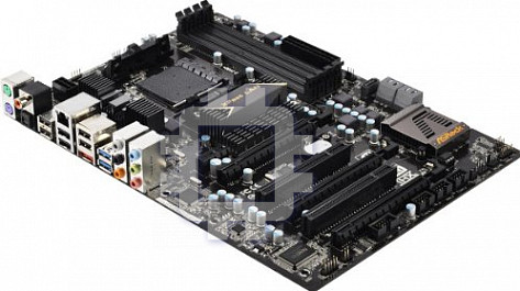
ASRock 990FX Extreme3 Motherboard
(ATX Form Factor: 12.0-in x 8.6-in, 30.5 cm x 21.8 cm)
ASRock 990FX Extreme3 Quick Installation Guide
ASRock 990FX Extreme3 Support CD
1 x ASRock SLI_Bridge_2S Card
2 x Serial ATA (SATA) Data Cables (Optional)
1 x 3.5mm Audio Cable (Optional)
1 x I/O Panel Shield
ASRock Reminds You...
®
TM
TM
To get better performance in Windows
7 / 7 64-bit / Vista
/ Vista
64
bit, it is recommended to set the BIOS option in Storage Conguration
to AHCI mode. For the BIOS setup, please refer to the “User Manual” in
our support CD for details.
5

1.2 Specifications
Platform - ATX Form Factor: 12.0-in x 8.6-in, 30.5 cm x 21.8 cm
- All Solid Capacitor design (100% Japan-made high-quality
Conductive Polymer Capacitors)
CPU - Support for Socket AM3+ processors
TM
- Support for Socket AM3 processors: AMD Phenom
II X6 /
X4 / X3 / X2 (except 920 / 940) / Athlon II X4 / X3 / X2 /
Sempron processors
- Supports 8-Core CPU
- Supports UCC feature (Unlock CPU Core) (see CAUTION 1)
- 4 + 1 Power Phase Design
- Supports CPU up to 140W
TM
- Supports AMD’s Cool ‘n’ Quiet
Technology
- FSB 2600 MHz (5.2 GT/s)
- Supports Untied Overclocking Technology (see CAUTION 2)
- Supports Hyper-Transport 3.0 (HT 3.0) Technology
Chipset - Northbridge: AMD 990FX
- Southbridge: AMD SB950
Memory - Dual Channel DDR3 Memory Technology (see CAUTION 3)
- 4 x DDR3 DIMM slots
- Supports DDR3 2100(OC)/1866/1600/1333/1066/800
non-ECC, un-buffered memory (see CAUTION 4)
- Max. capacity of system memory: 64GB (see CAUTION 5)
Expansion Slot - 3 x PCI Express 2.0 x16 slots (PCIE2/PCIE3: x16 mode;
PCIE4: x4 mode)
- 1 x PCI Express 2.0 x1 slot
- 2 x PCI slots
TM
TM
TM
- Supports AMD
Quad CrossFireX
, 3-Way CrossFireX
TM
and CrossFireX
®
TM
TM
- Supports NVIDIA
Quad SLI
and SLI
Audio - 7.1 CH HD Audio with Content Protection
(Realtek ALC892 Audio Codec)
- Premium Blu-ray audio support
LAN - PCIE x1 Gigabit LAN 10/100/1000 Mb/s
- Broadcom BCM57781
- Supports Wake-On-LAN
- Supports Energy Efcient Ethernet 802.3az
- Supports PXE
6

Rear Panel I/O I/O Panel
- 1 x PS/2 Mouse Port
- 1 x PS/2 Keyboard Port
- 1 x Coaxial SPDIF Out Port
- 1 x Optical SPDIF Out Port
- 6 x Ready-to-Use USB 2.0 Ports
- 2 x Ready-to-Use USB 3.0 Ports
- 1 x eSATA3 Connector
- 1 x RJ-45 LAN Port with LED (ACT/LINK LED and SPEED
LED)
- HD Audio Jack: Side Speaker/Rear Speaker/Central/Bass/
Line in/Front Speaker/Microphone (see CAUTION 6)
SATA3 - 5 x SATA3 6.0 Gb/s connectors, support RAID
(RAID 0, RAID 1, RAID 5, and RAID 10), NCQ,
AHCI and "Hot Plug" functions
USB 3.0 - 2 x Rear USB 3.0 ports by Etron EJ168A, support USB 1.0
/2.0/3.0 up to 5Gb/s
Connector - 5 x SATA3 6.0Gb/s connectors
- 1 x IR header
- 1 x COM port header
- 1 x HDMI_SPDIF header
- 1 x Power LED header
- CPU/Chassis/Power FAN connector
- 24 pin ATX power connector
- 8 pin 12V power connector
- Front panel audio connector
- 3 x USB 2.0 headers (support 6 USB 2.0 ports)
BIOS Feature - 32Mb AMI UEFI Legal BIOS with GUI support
- Supports “Plug and Play”
- ACPI 1.1 Compliance Wake Up Events
- Supports jumperfree
- SMBIOS 2.3.1 Support
- CPU, VCCM, NB, SB Voltage Multi-adjustment
Support CD - Drivers, Utilities, AntiVirus Software (Trial Version),
CyberLink MediaEspresso 6.5 Trial
Unique Feature - ASRock Extreme Tuning Utility (AXTU) (see CAUTION 7)
- ASRock Instant Boot
- ASRock Instant Flash (see CAUTION 8)
- ASRock APP Charger (see CAUTION 9)
- ASRock XFast USB (see CAUTION 10)
- ASRock XFast LAN (see CAUTION 11)
7

- ASRock On/Off Play Technology (see CAUTION 12)
- Hybrid Booster:
- CPU Frequency Stepless Control (see CAUTION 13)
- ASRock U-COP (see CAUTION 14)
- Boot Failure Guard (B.F.G.)
- Turbo 50 / Turbo 60 CPU Overclocking
- Turbo UCC
Hardware - CPU Temperature Sensing
Monitor - Chassis Temperature Sensing
- CPU/Chassis/Power Fan Tachometer
- CPU Quiet Fan
- CPU/Chassis Fan Multi-Speed Control
- Voltage Monitoring: +12V, +5V, +3.3V, Vcore
®
®
TM
TM
OS - Microsoft
Windows
7 / 7 64-bit / Vista
/ Vista
64-bit / XP
/ XP 64-bit compliant
Certications - FCC, CE, WHQL
- ErP/EuP Ready (ErP/EuP ready power supply is required)
(see CAUTION 15)
* For detailed product information, please visit our website: http://www.asrock.com
8

WARNING
Please realize that there is a certain risk involved with overclocking, including adjusting the
setting in the BIOS, applying Untied Overclocking Technology, or using third-party overclock-
ing tools. Overclocking may affect your system’s stability, or even cause damage to the
components and devices of your system. It should be done at your own risk and expense.
We are not responsible for possible damage caused by overclocking.
CAUTION!
1. ASRock UCC (Unlock CPU Core) feature simplies AMD CPU activa-
tion. Via a simple switch in the UEFI option “ASRock UCC”, you can
unlock the extra CPU core to enjoy an instant performance boost. When
UCC feature is enabled, the dual-core or triple-core CPU will boost to
the quad-core CPU, and some CPU, including quad-core CPU, can also
increase L3 cache size up to 6MB, which means you can enjoy the up-
grade CPU performance with a better price. Please be noted that UCC
feature is supported with AM3 CPU only, and in addition, not every AM3
CPU can support this function because some CPU’s hidden core may be
malfunctioned.
2. This motherboard supports Untied Overclocking Technology. Please read
“Untied Overclocking Technology” on page 41 for details.
3. This motherboard supports Dual Channel Memory Technology. Before
you implement Dual Channel Memory Technology, make sure to read the
installation guide of memory modules on page 17 for proper installation.
4. Whether 2100MHz memory speed is supported depends on the AM3/
AM3+ CPU you adopt. If you want to adopt DDR3 2100 memory module
on this motherboard, please refer to the memory support list on our web-
site for the compatible memory modules. Non OC mode’s DDR3 1866 is
supported by AM3+ CPU.
ASRock website http://www.asrock.com
5. Due to the operating system limitation, the actual memory size may be
®
less than 4GB for the reservation for system usage under Windows
7 /
TM
®
Vista
/ XP. For Windows
64-bit OS with 64-bit CPU, there is no such
limitation.
6. For microphone input, this motherboard supports both stereo and mono
modes. For audio output, this motherboard supports 2-channel, 4-chan-
nel, 6-channel, and 8-channel modes. Please check the table on page 13
for proper connection.
7. ASRock Extreme Tuning Utility (AXTU) is an all-in-one tool to ne-tune dif-
ferent system functions in a user-friendly interface, which includes Hard-
ware Monitor, Fan Control, Overclocking, OC DNA and IES. In Hardware
Monitor, it shows the major readings of your system. In Fan Control, it
shows the fan speed and temperature for you to adjust. In Overclocking,
you are allowed to overclock CPU frequency for optimal system per-
formance. In OC DNA, you can save your OC settings as a prole and
9

share it with your friends. Your friends then can load the OC prole to
their own system to get the same OC settings. In IES (Intelligent Energy
Saver), the voltage regulator can reduce the number of output phases to
improve efciency when the CPU cores are idle without sacricing com-
puting performance. Please visit our website for the operation procedures
of ASRock Extreme Tuning Utility (AXTU).
ASRock website: http://www.asrock.com
8. ASRock Instant Flash is a BIOS ash utility embedded in Flash ROM.
This convenient BIOS update tool allows you to update system BIOS
®
without entering operating systems rst like MS-DOS or Windows
. With
this utility, you can press the <F6> key during the POST or the <F2>
key to enter into the BIOS setup menu to access ASRock Instant Flash.
Just launch this tool and save the new BIOS le to your USB ash drive,
oppy disk or hard drive, then you can update your BIOS only in a few
clicks without preparing an additional oppy diskette or other complicated
ash utility. Please be noted that the USB ash drive or hard drive must
use FAT32/16/12 le system.
9. If you desire a faster, less restricted way of charging your Apple devices,
such as iPhone/iPad/iPod Touch, ASRock has prepared a wonderful solu-
tion for you - ASRock APP Charger. Simply install the APP Charger driv-
er, it makes your iPhone charge much quickly from your computer and
up to 40% faster than before. ASRock APP Charger allows you to quickly
charge many Apple devices simultaneously and even supports continu-
ous charging when your PC enters into Standby mode (S1), Suspend to
RAM (S3), hibernation mode (S4) or power off (S5). With APP Charger
driver installed, you can easily enjoy the marvelous charging experience.
ASRock website: http://www.asrock.com/Feature/AppCharger/index.asp
10. ASRock XFast USB can boost USB storage device performance. The
performance may depend on the properties of the device.
11. ASRock XFast LAN provides a faster internet access, which includes
the benets listed below. LAN Application Prioritization: You can cong-
ure your application’s priority ideally and/or add new programs. Lower
Latency in Game: After setting online game’s priority higher, it can lower
the latency in games. Trafc Shaping: You can watch Youtube HD videos
and download simultaneously. Real-Time Analysis of Your Data: With
the status window, you can easily recognize which data streams you are
transferring currently.
12. ASRock On/Off Play Technology allows users to enjoy the great audio ex-
perience from the portable audio devices, such like MP3 player or mobile
phone to your PC, even when the PC is turned off (or in ACPI S5 mode)!
This motherboard also provides a free 3.5mm audio cable (optional) that
ensures users the most convenient computing environment.
13. Although this motherboard offers stepless control, it is not recommended
to perform over-clocking. Frequencies other than the recommended CPU
bus frequencies may cause instability of the system or damage the CPU.
10

14. While CPU overheat is detected, the system will automatically shutdown.
Before you resume the system, please check if the CPU fan on the
motherboard functions properly and unplug the power cord, then plug
it back again. To improve heat dissipation, remember to spray thermal
grease between the CPU and the heatsink when you install the PC sys-
tem.
15. EuP stands for Energy Using Product, was a provision regulated by the
European Union to define the power consumption for the completed
system. According to EuP, the total AC power of the completed system
should be under 1.00W in off mode condition. To meet EuP standards,
an EuP ready motherboard and an EuP ready power supply are required.
According to Intel’s suggestion, the EuP ready power supply must meet
the standard of 5v, and the standby power efciency should be higher
than 50% under 100 mA current consumption. For EuP ready power sup-
ply selection, we recommend you to check with the power supply manu-
facturer for more details.
11
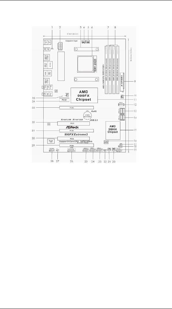
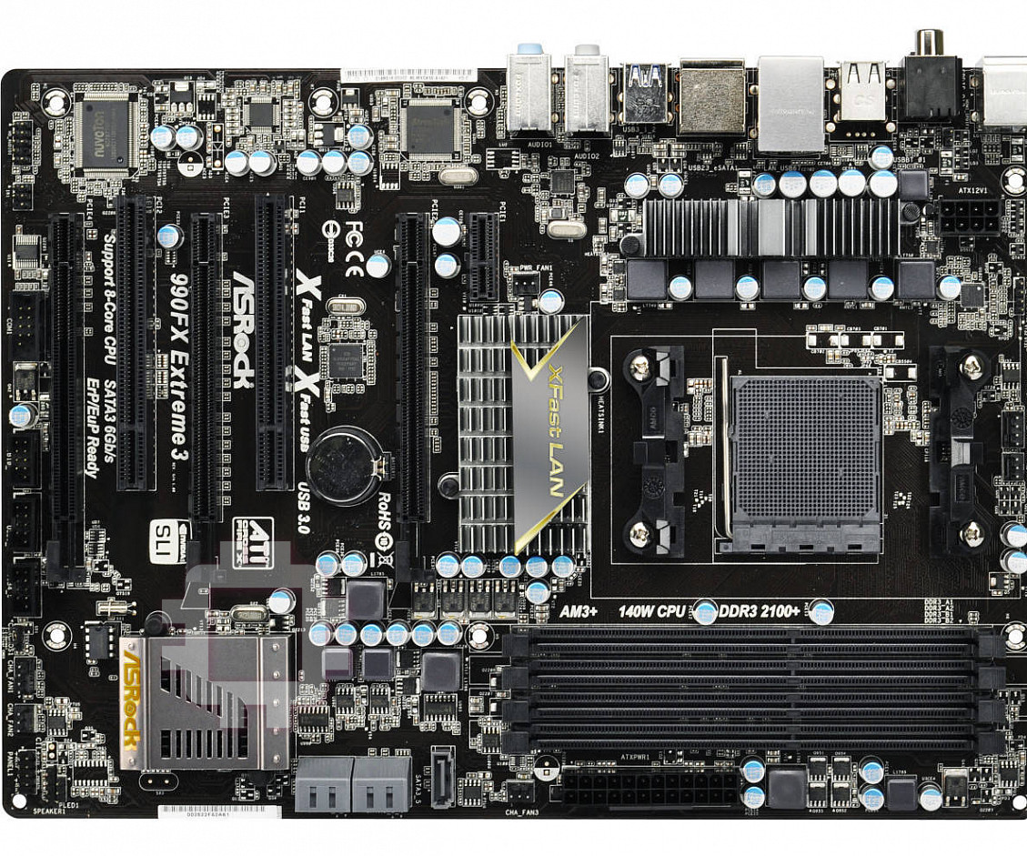
1.3 Motherboard Layout
1 HDMI_SPDIF Header (HDMI_SPDIF1, Black) 19 System Panel Header (PANEL1, Black)
2 ATX 12V Power Connector (ATX12V1) 20 Chassis Fan Connector (CHA_FAN2)
3 CPU Heatsink Retention Module 21 Chassis Fan Connector (CHA_FAN1)
4 CPU Fan Connector (CPU_FAN1) 22 Clear CMOS Jumper (CLRCMOS1)
5 CPU Fan Connector (CPU_FAN2) 23 USB 2.0 Header (USB4_5, Black)
6 AM3+ CPU Socket 24 USB 2.0 Header (USB8_9, Black)
7 2 x 240-pin DDR3 DIMM Slots 25 USB 2.0 Header (USB10_11, Black)
(Dual Channel B: DDR3_A1, DDR3_B1; Black) 26 Serial Port Connector (COM1)
8 2 x 240-pin DDR3 DIMM Slots 27 Infrared Module Header (IR1)
(Dual Channel B: DDR3_A2, DDR3_B2; Black) 28 Front Panel Audio Header
9 ATX Power Connector (ATXPWR1) (HD_AUDIO1, Black)
10 Chassis Fan Connector (CHA_FAN3) 29 PCI Express 2.0 x16 Slot
11 Northbridge Controller (PCIE4; Black)
12 SATA3 Connector (SATA3_5, Gray) 30 PCI Slot (PCI2)
13 SATA3 Connectors (SATA3_3_4, Gray) 31 PCI Express 2.0 x16 Slot
14 SATA3 Connectors (SATA3_1_2, Gray) (PCIE3; Black)
15 Southbridge Controller 32 PCI Slot (PCI1)
16 SPI Flash Memory (32Mb) 33 PCI Express 2.0 x16 Slot
17 Power LED Header (PLED1) (PCIE2; Black)
18 Chassis Speaker Header 34 PCI Express 2.0 x1 Slot (PCIE1; Black)
(SPEAKER 1, Black) 35 Power Fan Connector (PWR_FAN1)
12
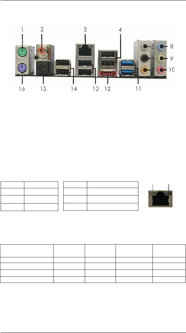
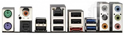
1.4 I/O Panel
1 PS/2 Mouse Port (Green) **9 Front Speaker (Lime)
2 Coaxial SPDIF Out Port 10 Microphone (Pink)
*3 LAN RJ-45 Port 11 USB 3.0 Ports (USB12)
4 USB 2.0 Ports (USB23) ***12 eSATA3 Connector
5 Side Speaker (Gray) 13 USB 2.0 Ports (USB67)
6 Rear Speaker (Black) 14 USB 2.0 Ports (USB01)
7 Central / Bass (Orange) 15 Optical SPDIF Out Port
8 Line In (Light Blue) 16 PS/2 Keyboard Port (Purple)
* There are two LEDs next to the LAN port. Please refer to the table below for the LAN port LED
indications.
LAN Port LED Indications
ACT/LINK
SPEED
Activity/Link LED SPEED LED
LED
LED
Status Description Status Description
Off No Link Off 10Mbps connection
Blinking Data Activity Orange 100Mbps connection
On Link Green 1Gbps connection
LAN Port
**
If you use a 2-channel speaker, please connect the speaker’s plug into “Front Speaker Jack”.
See the table below for connection details in accordance with the type of speaker you use.
TABLE for Audio Output Connection
Audio Output Channels Front Speaker Rear Speaker Central / Bass Side Speaker
(No. 9) (No. 6) (No. 7) (No. 5)
2 V -- -- --
4 V V -- --
6 V V V --
8 V V V V
13

To enable Multi-Streaming function, you need to connect a front panel audio cable to the front
panel audio header. After restarting your computer, you will nd “Mixer” tool on your system.
Please select “Mixer ToolBox” , click “Enable playback multi-streaming”, and click “ok”.
Choose “2CH”, “4CH”, “6CH”, or “8CH” and then you are allowed to select “Realtek HDA Pri-
mary output” to use Rear Speaker, Central/Bass, and Front Speaker, or select “Realtek HDA
Audio 2nd output” to use front panel audio.
*** eSATA3 connector supports SATA Gen3 in cable 1M.
14


