Sharp CV-P10PR: INSTALLATION AND REMOVAL OF EXHAUST HOSE Installation of the exhaust hose 1 2 3
INSTALLATION AND REMOVAL OF EXHAUST HOSE Installation of the exhaust hose 1 2 3: Sharp CV-P10PR
Table of contents
- A. Information on Disposal for Users (private households) B. Information on Disposal for Business Users.
- CONTENTS
- SAFETY PRECAUTIONS WARNINGS CAUTIONS
- LOCATION INCLUDED
- PART NAMES FRONT VIEW REAR VIEW
- REMOTE CONTROL
- INSTALLATION AND REMOVAL OF EXHAUST HOSE Installation of the exhaust hose 1 2 3
- 4 5 Removal of the exhaust hose
- USING THE REMOTE CONTROL LOADING BATTERIES HOW TO USE THE REMOTE CONTROL
- NOTE ON OPERATION NOTES ON OPERATION OPERATING CONDITIONS ENERGY EFFICIENCY TIPS
- USE FOR AIR CONDITIONER COOL MODE DRY MODE
- FAN MODE VENTILATION MODE
- USE FOR AIR CONDITIONER TO CHANGE AIR FLOW DIRECTION UP / DOWN AIR FLOW DIRECTION LEFT / RIGHT AIR FLOW DIRECTION
- TURBO COOL OPERATION TO CANCEL SLEEP OPERATION TO CANCEL
- TIMER ON TO CANCEL USE FOR AIR CONDITIONER TIMER OPERATION TIMER OFF
- USE FOR ION GENERATOR ION GENERATOR MODE
- USE FOR ION GENERATOR TO CHANGE AIR FLOW DIRECTION MAX DENSITY OPERATION
- REFRESH OPERATION TIMER OFF OPERATION
- MAIN UNIT OPERATION DRAINAGE
- MAINTENANCE CLEANING THE FILTER AIR INLET FILTER CLEANING THE UNIT AND THE REMOTE CONTROL WHEN STORING FOR A LONG PERIOD (NOT IN USE)
- BEFORE CALLING FOR SERVICE
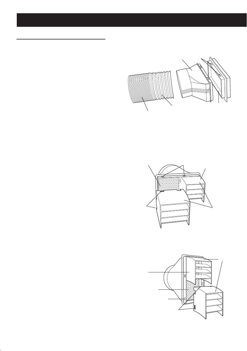
INSTALLATION AND REMOVAL OF EXHAUST HOSE
Installation of the exhaust hose
Attach the insect guard net to the
1
window adapter.
Hole
Window adapter
Push the insect guard net rmly to en-
sure that four projections on the window
adapter t into the four holes on it.
Attach the window adapter to the
2
exhaust hose.
Extend one end of the exhaust hose and
Extend
Insect guard net
insert it into the window adapter, and
Exhaust hose
turn it (approx. three times) until it stops.
Make sure they are securely attached.
Attach the rain guards to the in-
Horizontally placed
3
sect guard net.
Insert all three projections on each rain
Insect guard net
Hole
Rain guard
guard into the holes in the insect guard
net.
Side “A” will now be at the top, as indi-
cated in the diagram.
Projection
"A"
Vertically placed
"A"
Rain guard
Insect guard net
Hole
Projection
GB-6
01_CV-P10PR_OM_EN.indd 6 14/08/29 16:42
