Xylem e-NSC, e-NSCF, e-NSCC: 4 Installation
4 Installation: Xylem e-NSC, e-NSCF, e-NSCC
en - Translation of the original instructions
Installation above liquid source (suction lift)
NOTICE:
The theoretical maximum suction height of any pump is 10.33m. In
If you use a different motor from the standard one supplied with the
practice, the following affect the suction capacity of the pump:
electric-pump, check the relevant instructions to find out the permitted
number of starts per hour.
• Temperature of the liquid
• Elevation above the sea level (in an open system)
• System pressure (in a closed system)
Noise level
• Resistance of the pipes
See the measuring surface sound pressure levels L
pA
in Table 15 .
• Own intrinsic flow resistance of the pump
• Height differences
The following equation is used to calculate the maximum height above
4 Installation
the liquid level which the pump can be installed:
(p
b
*10.2 - Z) ≥ NPSH + H
f
+ H
v
+ 0.5
Precautions
p
b
Barometric pressure in bar (in closed system is system pres-
WARNING:
sure)
• Observe accident prevention regulations in force.
NPSH Value in meter of the pump intrinsic flow resistance
• Use suitable equipment and protection.
H
f
Total losses in meters caused by passage of liquid in the suc-
• Always refer to the local and/or national regulations,
tion pipe of the pump
legislation, and codes in force regarding the selection of
H
v
Steam pressure in meters that correspond to the temperature
the installation site, plumbing, and power connections.
of the liquid T °C
Electrical Hazard:
0.5 Recommended safety margin (m)
• Make sure that all connections are performed by quali-
Z Maximum height at which the pump can be installed (m)
fied installation technicians and in compliance with the
For more information, see Figure 17 .
regulations in force.
• Before starting work on the unit, make sure that the unit
(p
b
*10.2 - Z) must always be a positive number.
and the control panel are isolated from the power sup-
NOTICE:
ply and cannot be energized. This applies to the control
circuit as well.
Do not exceed the pumps suction capacity as this could cause cavita-
tion and damage the pump.
Grounding (earthing)
4.1.2 Piping requirements
Electrical Hazard:
• Always connect the external protection conductor to
Precautions
ground (earth) terminal before making other electrical
connections.
WARNING:
• You must ground (earth) all electrical equipment. This
• Use pipes suited to the maximum working pressure of
applies to the pump equipment, the driver, and any
the pump. Failure to do so can cause the system to
monitoring equipment. Test the ground (earth) lead to
rupture, with the risk of injury.
verify that it is connected correctly.
• Make sure that all connections are performed by quali-
• If the motor cable is jerked loose by mistake, the
fied installation technicians and in compliance with the
ground (earth) conductor should be the last conductor
regulations in force.
to come loose from its terminal. Make sure that the
ground (earth) conductor is longer than the phase con-
NOTICE:
ductors. This applies to both ends of the motor cable.
Observe all regulations issued by authorities having jurisdiction and by
• Add additional protection against lethal shock. Install a
companies managing the public water supplies if the pump is connect-
high-sensitivity differential switch (30 mA) [residual cur-
ed to a public water system. If required, install appropriate backflow-
rent device RCD].
prevention device on the suction side.
4.1 Facility requirements
Piping checklist
4.1.1 Pump location
Check that the following requirements are met:
• All piping is independently supported, piping must not place a bur-
DANGER:
den on the unit.
Do not use this unit in environments that may contain flam-
• Flexible pipes or unions are used, in order to avoid transmission
mable/explosive or chemically aggressive gases or powders.
of pump vibrations to the pipes and vice versa.
• Use wide bends, avoid using elbows which cause excessive flow
resistance.
Guidelines
• The suction piping is perfectly sealed and airtight.
Observe the following guidelines regarding the location of the product:
• If the pump is used in an open circuit, then the diameter of the
• Make sure that no obstructions hinder the normal flow of the cool-
suction pipe is suited to the installation conditions. The suction
ing air that is delivered by the motor fan.
pipe must not be smaller than the diameter of the suction port.
• Make sure that the installation area is protected from any fluid
• If the suction piping must be larger than the suction side of the
leaks, or flooding.
pump, then an eccentric pipe reducer is installed.
• If possible, place the pump slightly higher than the floor level.
• If the pump is placed above liquid level, a foot valve is installed at
• The ambient temperature must be between 0°C (+32°F) and
the end of the suction piping.
+40°C (+104°F).
• The foot valve is fully immersed into the liquid so that air cannot
• The relative humidity of the ambient air must be less than 50% at
enter through the suction vortex, when the liquid is at the mini-
+40°C (+104°F).
mum level and the pump is installed above the liquid source.
• Contact the Sales and Service Department if:
• Appropriately sized on-off valves are installed on the suction pip-
• The relative air humidity conditions exceed the guidelines.
ing and on the delivery piping (downstream to the check valve) for
• The room temperature exceeds +40°C (+104°F).
regulation of the pump capacity, for pump inspection, and for
• The unit is located more than 1000 m (3000 ft) above the
maintenance.
sea level. The motor performance may need to be de-rated
• Appropriately sized on-off valve is installed on the delivery piping
or replaced with a more powerful motor.
(downstream to the check valve) for regulation of the pump ca-
pacity, for pump inspection, and for maintenance.
For information about which value to de-rate the motor with, see Table
• In order to prevent back flow into the pump when pump is turned
16 .
off a check valve is installed on the delivery piping.
Pump positions and clearance
Provide adequate light and clearance around the pump. Make sure
that it is easily accessible for installation and maintenance operations.
e-NSC Installation, Operation, and Maintenance Manual 15
en - Translation of the original instructions
WARNING:
NOTICE:
Do not use the on-off valve on the discharge side in the
• Only use dynamically balanced motors with a half-sized key in the
closed position in order to throttle the pump for more than a
shaft extension (IEC 60034-14) and with normal vibration rate (N).
few seconds. If the pump must operate with the discharge
• The mains voltage and frequency must agree with the specifica-
side closed for more than a few seconds, a bypass circuit
tions on the data plate.
must be installed to prevent overheating of the liquid inside
• Only use single-phase or three-phase motors whose size and
the pump.
power comply with the European standards.
For illustrations that show the piping requirements, see Figure 18 and
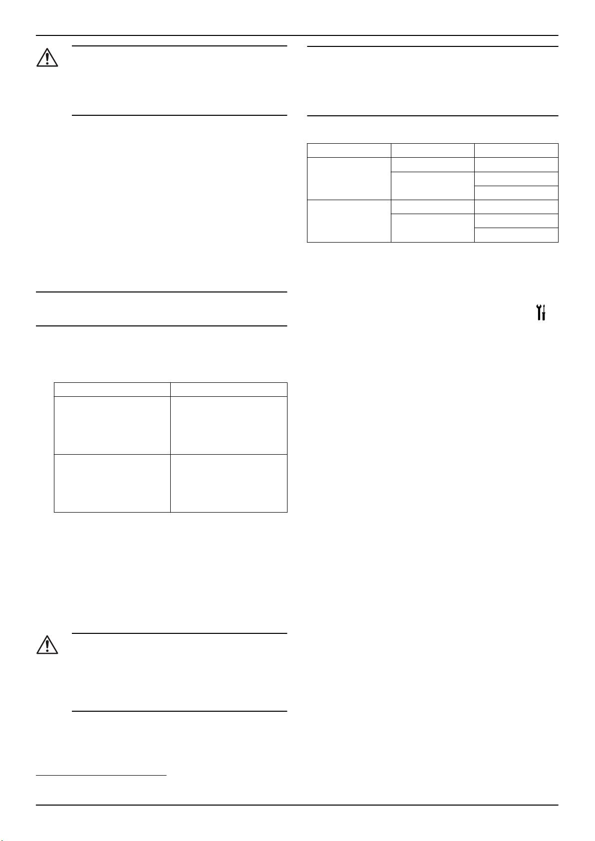
In general, motors can operate under the following mains voltage toler-
Figure 19 .
ances:
4.2 Electrical requirements
Frequency Hz Phase ~ UN [V] ± %
• The local regulations in force overrule these specified require-
50 1 220 – 240 ± 6
ments.
• In the case of fire fighting systems (hydrants and/or sprinklers),
3 230/400 ± 10
check the local regulations in force.
400/690 ± 10
Electrical connection checklist
60 1 220 – 230 ± 6
Check that the following requirements are met:
3 220/380 ± 5
• The electrical leads are protected from high temperature, vibra-
tions, and collisions.
380/660 ± 10
• The power supply line is provided with:
• A short-circuit protection device
Use cable according to rules with 3 leads (2+earth/ground) for single
• A mains isolator switch with a contact gap of at least 3 mm
phase versions and with 4 leads (3+earth/ground) for three phase ver-
sion.
The electrical control panel checklist
4.3 Install the pump
NOTICE:
The control panel must match the ratings of the electric pump. Improp-
4.3.1 Mechanical installation
er combinations could fail to guarantee the protection of the motor.
Check the following before installation:
• Use a concrete of compressive strength class C12/15 which
Check that the following requirements are met:
meets the requirements of exposure class XC1 to EN 206-1.
• The control panel must protect the motor against overload and
• The mounting surface must have set and must be completely hor-
short-circuit.
izontal and even.
• Install the correct overload protection (thermal relay or motor pro-
• Observe the weights indicated.
tector).
Mount the unit to a foundation
Pump Type
Protection
For information about the pump base and anchor holes, see Figure
Single phase standard electric
• Built-in automatic reset
20 .
pump ≤ 1,5 kW
thermal-amperometric pro-
Check that the foundation has been prepared in accordance with the
tection (motor protector)
dimensions given in the outline drawing/general arrangement drawing.
• Short circuit protection
(must be supplied by the
1. Position the pump set on the foundation and level it with the help
3
installer)
of a spirit level that is placed on the shaft and discharge nozzle.
Three phase electric pump and
• Thermal protection (must
The permissible deviation is 0.2 mm/m.
4
other single phase pumps
be supplied by the instal-
2. Remove the plugs covering the ports.
ler)
3. Align the pump and piping flanges on both sides of the pump.
• Short circuit protection
Check the alignment of the bolts.
(must be supplied by the
installer)
4. Fasten the piping with bolts to the pump. Do not force the piping
into place.
• The control panel must be equipped with a dry-running protection
system to which a pressure switch, float switch, probes, or other
5. Use shims (2) for height compensation, if necessary.
suitable device is connected.
Always fit shims, if any, immediately to the left and right of the
• The following devices are recommended for use on the suction
foundation bolts (3) between the baseplate/foundation frame and
side of the pump:
the foundation. For a bolt-to-bolt distance (L) > 800 mm, fit extra
• When the liquid is pumped from a water system, use a pres-
shims (2) halfway between the bolt holes.
sure switch.
6. Make sure that all shims lie perfectly flush.
• When the liquid is pumped from a storage tank or reservoir,
7. Insert the foundation bolts (3) into the holes provided.
use a float switch or probes.
• When thermal relays are used, relays that are sensitive to phase
8. Use concrete to set the foundation bolts (3) into the foundation.
failure are recommended.
9. Wait until the concrete has set firmly, and then level the base-
plate.
The motor checklist
10. Tighten the foundation bolts (3) evenly and firmly.
WARNING:
Note:
• Read the operating instructions in order to ensure
• For baseplates, it is recommended to grout the baseplate with
whether a protection device is provided if another motor
low-shrinkage concrete.
other than the standard is used.
• If the transmission of vibrations can be disturbing, provide vibra-
• If the motor is equipped with automatic thermal protec-
tion-damping supports between the pump and the foundation.
tors, be aware of the risk of unexpected starts in con-
nection to overload. Do not use such motors for fire-
Mount the pump to a base frame
fighting applications and sprinkler systems.
Be sure to check that the following are adhered to:
• Solid base frame which does not twist or vibrate during operation
(resonance).
• Mounting surfaces of the pump feet and the motor on the base
frame must be flat (machining is recommended).
• Safe fastening of pump and motor must be guaranteed.
3
fuses aM (motor starting), or magneto-thermal switch with curve C and Icn ≥ 4,5 kA or other equivalent device.
4
Overload thermal relay with operation class 10A + fuses aM (motor starting) or motor protection magneto-thermal switch with operation class 10A.
16 e-NSC Installation, Operation, and Maintenance Manual
en - Translation of the original instructions
• Adequate space between pump and motor shaft must be left de-
• The radial and axial deviation between the two coupling
pending on the used coupling.
halves must not exceed the values in table xyz, during
• Between pump and base frame must be an adequate shimming,
standstill as well as at operating temperature and under inlet
so that in case of replacement the same height between bottom
pressure.
and centerline can be adjusted (recommended vertical adjust-
ment 4-6 mm).
NOTICE:
Mount coupling guard after alignment and before start-up.
4.3.2 Piping checklist
Check that the following are adhered to:
Note: Control alignment of coupling again in operation warm condition
and on system pressure (if available) and correct, if necessary. Pay at-
• The suction lift line has been laid with a rising slope, at positive
tention to chapter 6 beforehand! It must be possible to turn the unit
suction head line with a downward slope towards the pump.
easily and harmoniously by hand.
• The nominal diameters of the pipelines are at least equal to the
nominal diameters of the pump nozzles.
NOTICE:
• The pipelines have been anchored in close proximity to the pump
Improper alignment of the unit can lead to damages at coupling and
and connected without transmitting any stresses or strains.
unit.
CAUTION:
Welding beads, scale and other impurities in the piping dam-
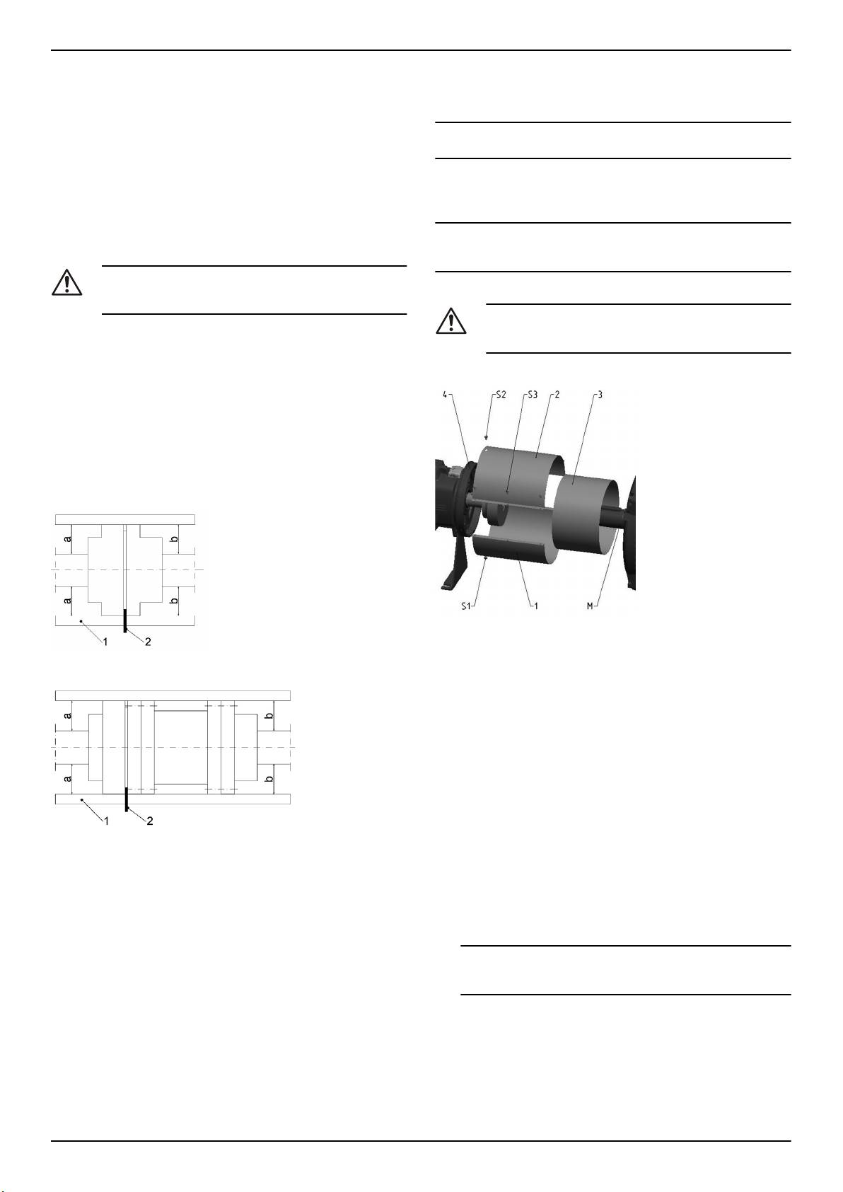
4.3.4 Install the coupling guard
age the pump.
CAUTION:
• Free the piping from any impurities.
Never operate the pump without the coupling guard correctly
• If necessary, install a filter.
installed.
• Follow the “Permitted Forces and torques on the flanges", see
Figure 21 .
Figure 6: Coupling guard parts
The data on forces and moments apply to static pipelines only. The
values are only applicable if the pump is installed on a baseplate and
bolted to a rigid and level foundation.
4.3.3 Coupling alignment
After mounting to the foundation and the connection of the piping, the
coupling must be adjusted again, even if the unit was delivered com-
pletely mounted on the frame.
Figure 4: Alignment of standard coupling
1. Coupling guard lower half
2. Coupling guard upper half
3. Adjusting half
Figure 5: Alignment of spacer coupling
1. Screw coupling guard lower half (1) with screws (S1)to bottom of
bearing cover (4) ring.
2. Insert adjusting piece (3) with slot downward and press it axially
to the motor.
3. Screw coupling guard upper half (1) with screws (S2) to the upper
side of the bearing cover (4) ring.
4. Screw parts 1 and 2 together, which fixes the adjusting piece.
4.3.5 Electrical installation
1. Remove the screws of the terminal box cover.
2. Connect and fasten the power cables according to the applicable
wiring diagram.
1. Coupling guard upper half
For wiring diagrams, see Figure 24 . The diagrams are also avail-
2. Coupling guard lower half
able on the back of the terminal box cover.
3. Adjusting piece
a) Connect the ground (earth) lead.
Remove the coupling guard.
Make sure that the ground (earth) lead is longer than the
1. Loosen the support foot and re-tighten it without transmitting any
phase leads.
stresses and strains.
b) Connect the phase leads.
2. Place the ruler (1) axially on both coupling halves.
3. Mount the terminal box cover.
3. Leave the ruler (1) in this position and turn the coupling by hand.
• The coupling is aligned correctly if the distances a and b to
NOTICE:
the respective shafts are the same at all points around the
Tighten the cable glands carefully to ensure protection against ca-
circumference.
ble slipping and humidity entering the terminal box.
• The radial and axial deviation between the two coupling
halves must not exceed the values in table xyz, during
4. If the motor is not equipped with automatic reset thermal protec-
standstill as well as at operating temperature and under inlet
tion, then adjust the overload protection according to the list be-
pressure.
low.
4. Check the distance (dimension see general arrangement draw-
ing) between the two coupling halves around the circumference
with a gauge (4). The coupling is correctly aligned if the distance
between the two coupling halves is the same at all points around
the circumference.
e-NSC Installation, Operation, and Maintenance Manual 17
Оглавление
- 1 Introduzione e sicurezza
- 2 Movimentazione e stoccaggio
- 4 Installazione
- 5 Messa in funzione, avvio,
- 7 Risoluzione dei problemi
- 1 Introduction and Safety
- 2 Transportation and Storage
- 4 Installation
- 5 Commissioning, Startup,
- 7 Troubleshooting
- 1 Introduction et sécurité
- 2 Transport et stockage
- 4 Installation
- 5 Contrôle de réception, Démarrage, Fonctionnement et Extinction
- 7 Recherche des pannes
- 1 Einführung und Sicherheit
- 2 Transport- und Lagerung
- 4 Montage
- 5 Inbetriebnahme, Anfahren,
- 7 Fehlerbehebung 6 Wartung
- 1 Giriş ve Güvenlik
- 2 Taşıma ve Depolama
- 4 Montaj
- 5 Devreye alma, Başlatma,
- 7 Sorun Giderme
- 1 Подготовка и техника
- 2 Транспортирование и
- 4 Установка
- 5 Ввод в эксплуатацию, запуск,
- 6 Техническое обслуживание
