Xylem ECOCIRC Vario Auto IM rev. B: инструкция
Раздел: Инструмент, электроинструмент, силовая техника
Тип: Насос
Инструкция к Насосу Xylem ECOCIRC Vario Auto IM rev. B
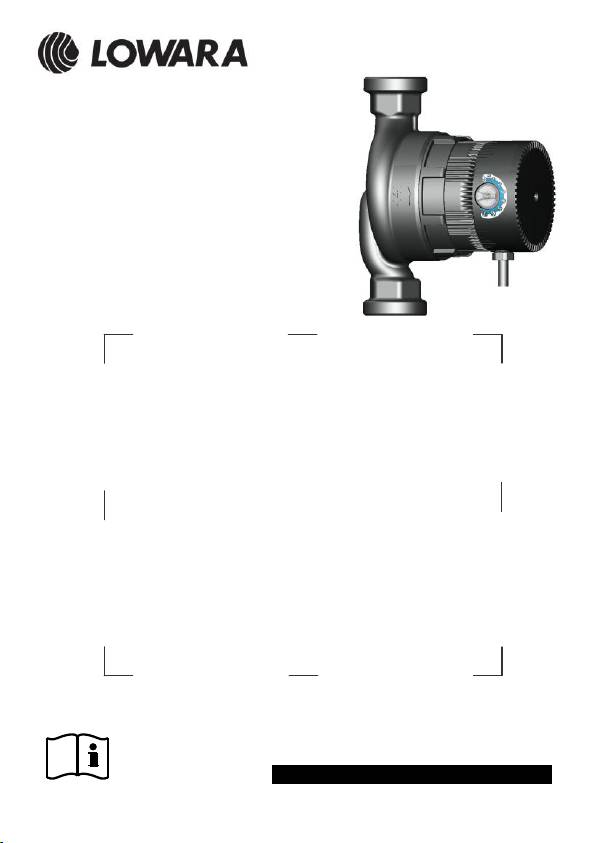
Ecocirc
Applica qui l’adesivo col codice a barre
Here apply the bar code label
- cod. 671075133 rev. B ed. 02/2013-

it
Istruzioni d’installazione ed uso
3
en
Installation and operating instructions
12
fr
Instructions pour l’installation et l’utilisation
21
de
Installations- und Bedienungsanleitungen
31
es
Instrucciones para la instalación y el uso
40
pt
Instruções para instalação e utilização
49
nl
Aanwijzingen voor de installatie en het gebruik
58
da
Instruktioner vedrørende installation og brug
67
no
Instruksjoner for installasjon og bruk
76
sv
Installations- och bruksanvisning
85
fi
Asennus- ja käyttöohjeet
94
cs
Návod na montáž a použití
103
hu
Telepítési és használati kézikönyv
112
ro
Instrucţiuni de instalare şi de funcţionare
121
ru
Инструкция по монтажу и эксплуатации
130
it
Conservate con cura il manuale per future consultazioni
en
Keep this manual for future reference
fr
Conservez avec soin le manuel pour toute consultation future
de
Das Handbuch muss für zukünftige Konsultationen sorgfältig
aufbewahrt werden.
es
Guarde con cuidado el manual para poderlo consultar en el futuro
pt
Conserve cuidadosamente o manual para consultas futuras
nl
Bewaar de handleiding zorgvuldig voor latere raadpleging
da
Gem manualen til senere brug
no
Les håndboken før bruk og oppbevar den med omhu
sv
Spara bruksanvisningen för framtida bruk
fi
Säilytä käyttöopas huolellisesti
cs
Manuál uchovejte pro pozdější použití
hu
Hu Gondosan őrizze meg a kézikönyvet jövőbeni szükség
esetére
ro
Păstraţi acest manual pentru a-l consulta în viitor
ru
Храните это руководство для использования в будущем
3
it
« Traduzione delle istruzioni originali »
Attenersi alle presenti istruzioni d’installazione ed uso durante
l’installazione e l’uso. Leggerle attentamente. Si consiglia di conservarle
nel luogo di utilizzo del dispositivo. Prestare particolare attenzione alle
istruzioni contrassegnate come segue:
Avvertenza la cui mancata osservanza potrebbe avere
conseguenze sulla sicurezza delle persone.
Avvertenza la cui mancata osservanza potrebbe
compromettere il funzionamento perfetto dell’apparecchio
e provocare dei danni.
1. Istruzioni per la sicurezza
Il presente apparecchio non deve essere utilizzato da
bambini o da persone con ridotte capacità fisiche,
sensoriali o mentali né da persone prive di esperienza o
conoscenze, se non sotto adeguata supervisione o dopo
aver ricevuto le necessarie istruzioni.
I bambini devono essere controllati in ogni caso e non
devono giocare con il apparecchio.
La pompa NON deve essere utilizzata se il cavo o la
protezione sono danneggiati.
In caso di cavo danneggiato, quest’ultimo deve essere
sostituito da una delle parti seguenti: il produttore, il suo
servizio di assistenza autorizzato o un elettricista
professionista.
Osservare inoltre le altre normative applicabili: per esempio, i
regolamenti sulla prevenzione degli incidenti o le istruzioni interne per
l’utilizzo e la sicurezza del produttore del sistema.
Il mancato rispetto di tali istruzioni può portare alla perdita di tutti i diritti al
risarcimento dei danni.
2. Descrizione generale (figura 6)
Le pompe di circolazione Ecocirc sono pompe a motore sferico senza
albero con tecnologia a magnete permanente commutato
elettronicamente (tecnologia ECM) a risparmio energetico, destinate a
sistemi di riscaldamento ad acqua calda, pompe di calore, impianti solari,
impianti di climatizzazione, circuiti di raffreddamento chiusi e impianti di
circolazione industriali.
ATTENZIONE

4
Per ragioni tecniche, le pompe a motore sferico hanno solo una
superficie d’appoggio minima del rotore sulla sfera del cuscinetto in
ceramica, per cui anche dopo un lungo periodo di inattività, per esempio
dopo la pausa estiva, è richiesta una coppia molto ridotta per avviare la
pompa. Le pompe non necessitano di una vite di sfiato / sblocco (quindi
ne sono sprovviste).
La pompa Ecocirc ha due modalità di funzionamento standard e due
ausiliarie:
Velocità costante = L’utente può impostare la velocità della
pompa girando la manopola in una
qualsiasi posizione compresa tra 1 e 7,
essendo quest’ultima la velocità massima.
La velocità preimpostata resta constante,
indipendentemente dalla portata.
Pressione proporzionale = L’utente può impostare la potenza
massima della pompa portando la
manopola in una qualsiasi posizione
compresa tra 1 e 7, essendo quest’ultima
la potenza massima. La pompa riduce
automaticamente la velocità a bassa
portata, consentendo così un risparmio di
energia.
Sfiato aria automatico = L’utente può far fuoriuscire l’aria
intrappolata dalla stazione di pompaggio.
Standby = L’utente può tenere basso il consumo di
energia (<1W) quando non è necessario
che la pompa sia in funzione.
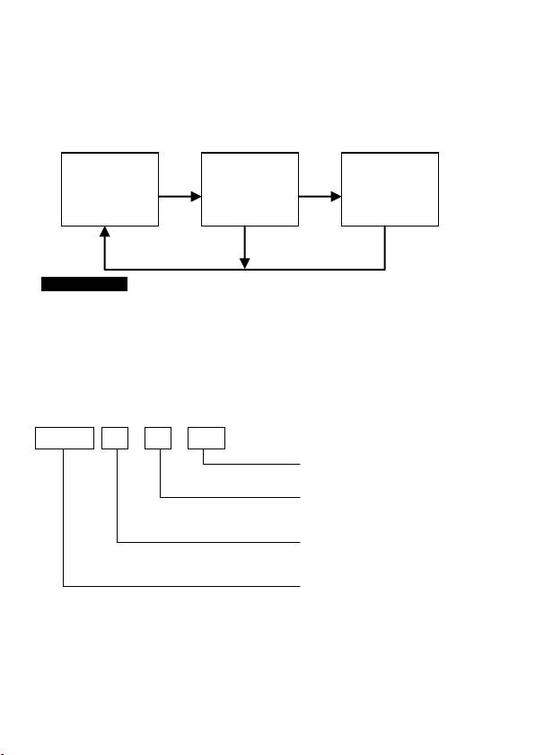
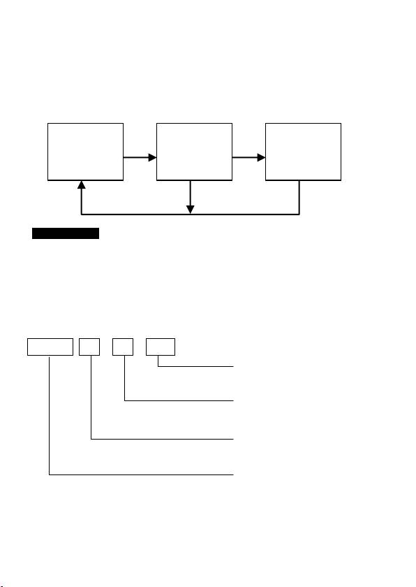
Istruzioni per il passaggio da una modalità di funzionamento ad un’altra:
- Per passare da una modalità di funzionamento standard all’altra
(pressione proporzionale e velocità costante), far ruotare la manopola
fino alla posizione inferiore e riportarla all’impostazione voluta entro 5
secondi. La pompa indica il cambiamento di modalità attraverso il
cambiamento del colore del LED della manopola (il colore per la
pressione proporzionale è il blu mentre quello per la velocità costante è
il bianco). In entrambi i casi, la luce è fissa.
- Per attivare la funzione di sfiato aria, portare la manopola nella
posizione inferiore e attendere almeno 5 secondi prima di riportarla
nell’impostazione desiderata. Per le istruzioni sullo sfiato aria, vedi
sezione 9. Una volta terminato il ciclo dello sfiato aria (circa 10 minuti),
la pompa tornerà alla modalità di funzionamento standard precedente.
Nota: se la manopola viene lasciata nella posizione inferiore, la pompa
entrerà in modalità standby al termine del ciclo dello sfiato d’aria.
- Per attivare la modalità standby senza passare attraverso l’intero ciclo
di sfiato aria, attivare in primo luogo la funzione sfiato aria, portare la
5
manopola su qualsiasi altra impostazione e, immediatamente, riportarla
nella posizione inferiore. Il LED ha una luce fissa. Per tornare a una
modalità di funzionamento standard, portare la manopola nella
posizione desiderata. Nota: il ritorno dalla modalità standby modifica la
modalità di funzionamento da Velocità Costante a Pressione
Proporzionale e viceversa. L’utente può resettare la modalità desiderata
come descritto nel primo paragrafo.
Campo di potenzialità fino a ca. 50 kW (riscaldamenti a
radiatore per una superfice fino a ca. 500 m²,
riscaldamenti a pavimento per una superficie pavimento
fino a ca. 200 m²). La potenzialità della pompa Ecocirc
non può essere adeguata mediante un controllo a taglio di
fase ("emissione di impulsi") della tensione di
alimentazione.
La versione disponibile può essere ricavata dal nome del modello, per
es.:
Ecocirc 25 – 4 / 130
DISTANZA INTERASSE
in mm
PREVALENZA MASSIMA
in m
DIAMETRO NOMINALE
DELLE BOCCHE
NOME SERIE
Modalità di
funzionam.
standard
Modalità
sfiato aria
Modalità
stand-by
ATTENZIONE

6
ESEMPIO: Ecocirc 25-4/130
Circolatore elettronico, serie Ecocirc, diametro nominale delle bocche =
25, prevalenza massima = 4 m, distanza interasse = 130 mm.
Si applica quanto segue:
Serie
Max. prevalenza
Max. portata
Ecocirc…-4
3,5 m
2500 l/h
Ecocirc…-6
5,7 m
3200 l/h
Diametro nominale
attacco DN
Per filettatura
tubo
Filettatura attacco
pompa
15
½“
G 1“
20
¾“
G 1 ¼“
25
1“
G 1 ½“
32
1¼“
G 2“
Lunghezza di montaggio (vedi figura 1): 130 mm, 180 mm
3. Dimensioni (vedi figura 1)
4. Caratteristiche tecniche
Modello di motore
Motore a sfera commutato
elettronicamente con rotore a magnete
permanente
“Ecocirc...-4”
“Ecocirc...-6”
Tensione nominale
200-240 V
200-240 V
Frequenza
50/60 Hz
50/60 Hz
Potenza assorbita
4-23 W
4-42 W
Protezione IP
IP 44
IP 44
Classe di isolamento
Classe F
Classe F
Pressione max. di
sistema
10 bar
10 bar
Gamma di temperature
consentita del liquido
pompato
da -10 °C* a +110
°C
da -10 °C* a +110
°C
Fluidi trasportatori
consentiti
Acqua di riscaldamento secondo VDI
2035, miscele acqua/glicole**
* Non deve congelare. Per evitare la condensazione, la
temperatura del liquido deve essere sempre superiore alla
temperatura ambiente.
** Le prestazioni della pompa cambiano notevolmente pompando
miscele acqua/glicole con concentrazioni superiori al 20%.
7
5. Curva caratteristica (vedi figura 2a + 2b)
6. Consigli per l’installazione
Per poter sostituire successivamente la pompa senza dover scaricare
completamente il sistema, si consiglia di installare una valvola di
intercettazione a monte e a valle della pompa.
7. Installazione
Non installare l’unità in aree a rischio di esplosioni e non
usarla per pompare liquidi infiammabili.
Figura 3: Installare l’unità in locali asciutti e a prova di congelamento in
una delle posizioni di montaggio consentite.
Figura 4: Quando è richiesto l’isolamento termico delle pompe, si
consiglia di utilizzare il guscio termoisolante tipo WD-B,
disponibile presso il produttore. Se si utilizzano altri materiali,
l’involucro del motore deve essere lasciato libero per evitare il
surriscaldamento del sistema elettronico e il disinserimento
automatico della pompa.
I raccordi a vite per l’installazione della pompa nell’impianto non sono
compresi nella fornitura, ma possono essere ordinati separatamente al
produttore come accessori.
Per il montaggio della pompa utilizzare guarnizioni nuove (comprese
nella fornitura).
Per la riduzione di un’eventuale propagazione del suono, il cliente deve
adottare adeguate misure finalizzate al disaccoppiamento o
all’isolamento acustico.
7.1 Collegamento elettrico (vedi figura 7)
L’allacciamento dell’unità deve essere effettuato
esclusivamente da elettricisti autorizzati. La pompa è
dotata di un cavo di serie.
In caso di modifiche all’allacciamento, questo deve essere
effettuato come mostrato nella figura 7. Le pompe
richiedono un salvamotore a parte installato sulla fase e
con un valore nominale di 10A.
La presa deve essere posizionata in modo tale da non
poter essere raggiunta dall’acqua nemmeno nel caso in
cui la tubazione subisca dei danni.
ATTENZIONE

8
7.2 Messa in funzione
Non è ammesso il funzionamento della pompa senza
liquido, in quanto ciò può causare danni irreparabili ai
cuscinetti in tempi brevissimi. Riempire con liquido prima
della prima messa in funzione.
Prima della messa in funzione, l’impianto deve essere:
- Lavato accuratamente per prevenire la presenza di corpi estranei e
impurità che potrebbero causare il blocco della pompa.
- Riempito interamente con i mezzi pompati (acqua o miscela
acqua/glicole).
- Sfiatato completamente dall’aria.
- Per facilitare quest’operazione, la pompa è dotata di una funzione
integrata di sfiato aria automatico. Vedi le istruzioni per l’attivazione di
tale funzione nella sezione 2 a pagina 4.
- La funzione di sfiato aria può essere attivata in qualsiasi momento
durante il funzionamento se si sospetta la presenza di aria.
- Se necessario, la funzione di sfiato aria può essere attivata varie volte
in una sequenza.
- La presenza di rumori di flusso udibili indica che nella pompa è ancora
presente dell’aria.
7.3 Impostazione tipica
I valori corrispondenti si ricavano dal calcolo idraulico dell’impianto. Se
tale calcolo non è disponibile, è possibile fare riferimento ai seguenti
valori di regolazione di velocità:
Abitazione standard
monofamiliare
Condominio
2
2
(circa 140 m
a 50 W/m
= 7 kW)
2
2
(circa 420 m
a 50 W/m
= 21 kW)
Ecocirc…-4
2-3
Ecocirc…-6
2-3
In caso di differenza di temperatura troppo grande tra mandata e ritorno,
aumentare la potenza; se la differenza di temperatura è minore del
previsto, diminuire ulteriormente la potenza. (Valori di riferimento:
riscaldamento a pavimento: 8–10 K; riscaldamento a radiatori: 15–20 K).
ATTENZIONE
9
8. Manutenzione/Smontaggio
Le pompe sono soggette ad usura. Se la pompa si blocca (vedi sezione
9) o si sentono rumori di sfregamento, controllare la pompa ed
eventualmente sostituirla se necessario in base alla procedura qui di
seguito descritta:
- Scollegare la pompa dalla rete.
- Chiudere le condutture di mandata e scarico. Se non
sono presenti dispositivi di blocco, svuotare il sistema in
modo che il livello del liquido sia inferiore a quello della
pompa.
- Allentare il dado per raccordi manualmente o con un
utensile adeguato (ad es. chiave a cinghia) e scollegare
attentamente il motore dall'involucro della pompa.
È possibile che dal vano rotore fuoriesca dell'acqua
residua. Fare in modo che il collegamento elettrico della
pompa non si bagni.
In riferimento alla figura 5:
- Estrarre manualmente l’unità rotore/girante verso l’alto.
- Se necessario, rimuovere eventuali corpi estranei o impurità e depositi
con un mezzo idoneo e inserire nuovamente l'unità rotore/girante.
- Il cuscinetto è usurato se l’unità rotore/girante non si può muovere
liberamente o se sono presenti tracce di sfregamento. In questo caso
sostituire il rotore, il motore della pompa o l’intera pompa.
9. Indicazione di esercizio / Panoramica dei guasti / Garanzia
Gli interventi sui componenti elettrici devono essere
eseguiti esclusivamente da elettricisti autorizzati.
Se il collegamento elettrico della pompa è stato effettuato correttamente
e la pompa è alimentata si accende una luce fissa bianca o blu (a
seconda della modalità di funzionamento attivata) nella manopola della
pompa Ecocirc.
Selezione della modalità: far ruotare la manopola fino alla posizione
finale 1 quindi riportarla indietro entro 5 secondi.
Velocità costante: luce bianca; Pressione proporzionale: luce blu
ATTENZIONE

10
I guasti vengono indicati come segue:
LED di indicazione di
esercizio /
Luce lampeggiante
Causa
Soluzione
Off
• Pompa non collegata o
collegata male
• Interruzione di corrente
• Verificare il collegamento
• Verificare rete + interruttore
3 volte breve, 1 volta
lunga
• Tensione troppo
bassa/troppo alta
• Verificare la tensione di
rete
4 volte breve
• Temperatura eccessiva
• La pompa si inserisce di
nuovo automaticamente
(vedi note seguenti)
• Determinare la max.
temperatura del sistema
2 volte breve + 1 volta
lunga + 1 volta breve
• Errore autoprova
• Rivolgersi al centro
assistenza autorizzato o al
punto vendita
2 volte breve + 2 volte
lunga
• Errore corrente
eccessiva
• Vedi sezione 8
Manutenzione/Smontaggio”
1 volta breve + 1 volta
lunga + 1 volta breve + 1
volta lunga
• Funzionamento
instabile
• Vedi sezione 8
Manutenzione/Smontaggio”
1 volta breve + 1 volta
lunga + 2 volte breve
• Errore avviamento
• Rotore bloccato
• Vedi sezione 8
Manutenzione/Smontaggio”
1 volta molto breve + 1
pausa lunga
• Funzione sfiato aria
• La pompa funziona in
modalità sfiato aria / il
colore indica la modalità
selezionata
In caso di altri guasti, procedere come segue:
Guasto
Causa
Soluzione
La pompa emette forti
rumori
• Sfiato non sufficiente
• Vedi sezione 7.2 “Messa
in
funzione”
• Presenza di corpi
estranei nella pompa
• Vedi sezione 8
“Manutenzione/
Smontaggio”
• Cuscinetto consumato
• Sostituire la pompa

11
Nota relativa alle temperature eccessive:
Per proteggere i componenti elettronici da temperature pericolosamente
alte, il sistema di controllo elettronico monitora la propria temperatura. Se
la temperatura misurata è troppo elevata, la velocità della pompa viene
ridotta. Se la temperatura supera il limite di sicurezza, la pompa si
spegne da sola e ripartirà automaticamente dopo essersi raffreddata.
10. Smaltimento
Questo prodotto e le sue parti devono essere smaltiti in modo ecologico.
Attenersi alle normative locali in materia.
11. Disegno esploso (vedi figura 6)
1. Cavo di alimentazione
2. Motore statore/pompa
3. Dado per raccordi
4. O-ring
5. Girante / Rotore
6. Involucro pompa
7. Filettatura raccordo
8. Regolatore di potenza continuo con LED di indicazione di esercizio
incorporato
12. DICHIARAZIONE CE DI CONFORMITÁ «TRADUZIONE»
LOWARA SRL UNIPERSONALE, CON SEDE IN VIA VITTORIO
LOMBARDI 14 - 36075 MONTECCHIO MAGGIORE VI - ITALIA,
DICHIARA CHE IL PRODOTTO
CIRCOLATORE (VEDI ADESIVO SU PRIMA PAGINA)
È CONFORME ALLE DISPOSIZIONI DELLE SEGUENTI DIRETTIVE
EUROPEE
• MACCHINE 2006/42/CE (ALLEGATO II: IL FASCICOLO TECNICO È
DISPONIBILE PRESSO XYLEM WATER SYSTEMS HUNGARY KFT,
KÜLSŐ-KÁTAI ÚT 41, 2700 CEGLÉD, MAGYARORSZÁG).
• COMPATIBILITÀ ELETTROMAGNETICA 2004/108/CE
E CONFORME ALLE SEGUENTI NORME TECNICHE
• EN 60335-1, EN 60335-2-51
• EN 55014-1:2006+A1:2009, EN 55014-2:1997+A1:2001+A2:2008
MONTECCHIO MAGGIORE, 31.07.2012
AMEDEO VALENTE
(DIRETTORE ENGINEERING e R&D)
rev.00
Lowara è un marchio registrato di Lowara srl Unipersonale, società controllata da Xylem
Inc.
12
en
« Original instructions »
These installation and operating instructions must be followed during
installation and operation. Read them carefully. We recommend that you
keep these instructions where the device is used. Particular attention
must be paid to instructions marked as follows:
Failure to follow these instructions may lead to personal
safety risks.
Failure to follow these instructions may lead to the
malfunction and possible damage of the device.
1. Safety instructions
This appliance is not to be used by children or persons
with reduced physical, sensory or mental capabilities, or
persons with a lack of experience or knowledge, unless
suitably supervised or unless provided with suitable
instructions.
Children should be supervised at all times and should not
play with appliance.
The pump must NOT be used with a damaged cord or
enclosure.
In the event of damage to the cord, the cord must be
replaced by one of the following parties: the manufacturer,
its authorized service center or a professional electrician.
Other relevant regulations should also be followed: e.g. accident
prevention regulations or the internal operating and safety instructions of
the system manufacturer.
Failure to follow these instructions can result in the loss of all entitlements
to claim damages.
2. General Description (figure 6)
Ecocirc circulation pumps are shaftless spherical motor pumps with
energy-efficient, electronically commutated permanent magnet
technology (ECM technology) for use in hot water heating systems, heat
pumps, solar systems, air conditioning systems, closed cooling circuits
and industrial circulation systems.
ATTENTION

13
For technical reasons, the contact surface between the rotor and the
ceramic ball bearing in spherical motor pumps is very small. For this
reason, even if they have not been in operation for a long time, such as
after the summer, only a small amount of torque is required to start the
pump. Ecocirc pumps do not require (and thus do not have) a
release/vent screw.
Ecocirc pump has two standard and two auxiliary operation modes:
Constant Speed = The user can set the speed of the pump by
turning the knob into any position between
1 and 7, 7 is the fastest. The preset speed
remains constant, independently from the
flow.
Proportional Pressure = The user can set the maximum strength of
the pump by turning the knob into any
position between 1 and 7, 7 is the
strongest. The pump automatically
decreases its speed at low flow, thus
providing energy saving.
Automatic Air Purge = The user can purge the trapped air from
the pumphouse.
Standby = The user can keep the power consumption
low (<1W) when pump operation is not
needed.
Instructions to change between operation modes:
- To change between standard operation modes (proportional pressure
and constant speed) the user shall turn the knob until the low end
position and turn the knob back to the desired setting within 5 sec.
Pump indicates mode change by switching the color of the knob LED
(proportional pressure is blue and constant speed is white). In both
cases the light is constant.
- To activate the air purge function the user shall turn the knob until the
low end position and wait at least 5 seconds before turning the knob
back to the desired setting. For air purge indication see section 9. After
air purge cycle finishes (approximately 10 minutes) the pump will return
to the previous standard operating mode.
Note: if user leaves the knob at the low end position pump will enter
standby mode after the air purge cycle finishes.
- To enter standby mode without going through the entire air purge cycle
the user shall first activate the air purge function, then, turn the knob to
14
any other setting and immediately turn it back to the low end position.
LED has a steady light. To return to a standard operation mode the user
shall turn the knob to the desired position. Note: returning from standby
changes the pump operation mode from Constant Speed to Proportional
Pressure and vice-versa. The user can reset the desired mode as
described in the first paragraph.
Heating system power range up to approx. 50 kW
(radiator heating systems up to approx. 500 m² living
space, underfloor heating systems up to approx. 200 m²
floor space). The power of the Ecocirc pump must not be
adjusted by applying phase trimming ("pulsing") to the
supply voltage.
The version at hand can be determined from the name of the model, e.g.:
Ecocirc 25 – 4 / 130
PORT to PORT
DISTANCE in mm
MAXIMUM NOMINAL
HEAD in m
RATED DIAMETER
OF PORTS
SERIES NAME
EXAMPLE: Ecocirc 25-4/130
Electronic circulator, series Ecocirc, rated diameter of ports = 25,
maximum head = 4 m, port-to-port distance = 130 mm.
The following applies:
Standard
operating
modes
Air purge
mode
Stand-by
mode
ATTENTION

15
Series
Max. delivery height
Max. delivery volume
Ecocirc…-4
3.5 m
2500 l/h
Ecocirc…-6
5.7 m
3200 l/h
Rated connection
width DN
For pipe thread
Pump connection
thread
15
½“
G 1“
20
¾“
G 1 ¼“
25
1“
G 1 ½“
32
1¼“
G 2“
Installation length (see fig. 1): 130 mm, 180 mm
3. Dimensions (see figure 1)
4. Technical Specifications
Motor model
Electronically commutated spherical motor
with permanent magnet rotor
“Ecocirc...-4”
“Ecocirc...-6”
Rated voltage
200-240 V
200-240 V
Frequency
50/60 Hz
50/60 Hz
Power consumption
4-23 W
4-42 W
IP protection
IP 44
IP 44
Insulation class
Class F
Class F
Max. system pressure
10 bar
10 bar
Permitted temperature
range of pumped fluid
-10 °C*to +110 °C
-10 °C* to +110 °C
Permitted pumping
media
Heating water according to VDI 2035,
water/glycol mixtures**
* Must not freeze. To avoid condensation the fluid temperature
must always be higher than the ambient temperature.
** Performance of the pump will noticeably change when pumping
water/glycol mixtures with concentrations higher than 20%.
16
5. Characteristic Curve (see figure 2a + 2b)
6. Installation Advice
The installation of a stop valve upstream and downstream of the pump is
recommended so the pump can be replaced at a later time without the
need to completely drain the system.
7. Installation
The unit may not be installed in areas where there is a
danger of explosion and may not be used to pump
flammable liquids.
Figure 3: Only install in dry, frost-proof rooms in one of the permitted
fitting positions.
Figure 4: The use of type WD-B thermal insulation shells, available from
the manufacturer, is recommended when a thermal insulation
of the pump is required. When using other materials, leave the
motor housing uninsulated, otherwise the electronics may
overheat and the pump may automatically switch off.
Screw connections for installing the pump in the system are not included
in the scope of delivery, but they may be ordered as accessories from the
manufacturer.
Use new gaskets (included in the scope of delivery) when installing the
pump.
The customer must take appropriate isolation measures and provide
appropriate acoustic insulation to reduce possible noise transfer.
7.1 Electrical connection (see figure 7)
The unit may only be connected by an authorized
electrician. The pump is equipped with a factory installed
cable.
In case of changing the connection, it must be made as
shown in figure 7. The pump requires a separate circuit
breaker installed on the phase with a rated value of 10A.
The socket must be positioned in such way that no water
can drip onto it even in the event of damage to the piping.
ATTENTION

17
7.2 Getting started
The pump must not run dry as this can result in the
destruction of the bearing in a very short time. Fill it with
liquid before first start-up.
Before starting, the system must be:
- Rinsed thoroughly to prevent the presence of foreign objects and
impurities which could block the pump.
- Fully filled with the pumped media (water or water-glycol mix).
- Completely purged of air.
- To help to reach this, the pump has a built-in automatic air purge
function. See instructions for activating the air purge function in
section 2 page 4.
- The air purge function can be activated any time during operation
when the presence of air is suspected in the system.
- The air purge function can be activated several times in a sequence if
necessary.
- Audible flow noise indicates that there is still air in the pump.
7.3 Typical setting
The corresponding values are derived from the hydraulic calculation of
the system. If this calculation is not at hand, then the following speed
settings can be used:
Standard single-family home
Apartment block
2
2
(approx. 140 m
@ 50 W/m
= 7 kW)
2
2
(approx. 420 m
@ 50 W/m
= 21 kW)
Ecocirc…-4
2-3
Ecocirc…-6
2-3
If the temperature differential between the flow and the return is too large,
increase the power; if the temperature differential is less than expected,
reduce the power even further. (Guideline values: underfloor heating: 8–
10 K; radiator heating: 15–20 K).
ATTENTION
18
8. Maintenance/Disassembly
Pumps are subject to wear. If the pump is blocked (see section 9) or
grinding noises are audible, check the pump and replace it if necessary.
Procedure:
- Disconnect the pump from the mains.
- Shut off supply and drain lines. If there are no shut-off
devices, drain the system so that the fluid level is
beneath that of the pump.
- Loosen the union nut by hand or with an appropriate
tool (such as a strap wrench) and carefully pull the
motor out of the pump housing.
Residual water may leak out of the rotor cavity. Prevent
the pump's electrical connection from getting wet.
For figure 5:
- Carefully but firmly pull the rotor / impeller upward by hand and remove
it.
- If necessary, remove foreign bodies and impurities/deposits with
appropriate agents. Reinsert the rotor / impeller.
- The bearing is worn if the rotor / impeller cannot be freely moved or if
wear marks are visible. In this case, replace the rotor, the pump motor,
or the entire pump.
9. Operating signal light / Troubleshooting / Warranty
Work on electrical parts may only be performed by
authorized electricians.
When the electrical connection to the pump is properly made and the
pump is powered, a white or blue light (depending on the actual operation
mode) is constantly lit in the knob of the Ecocirc pump.
Mode selection: turn the knob to the end position below 1 then turn it
back within 5 sec.
Constant Speed: white light; Proportional Pressure: blue light
Faults are indicated as follows:
Operating LEDs /
Blinking light
Cause
Solution
Off
• Pump is not connected
or is incorrectly
connected
• Power failure
• Check connection
• Check mains + circuit
breaker
ATTENTION

19
3 x short + 1 x long
• Voltage too low / too
high
• Check mains voltage
4 x short
• Temperature too high
• Pump restarts
automatically
(see the notes below)
• Determine max. system
temperature
2 x short + 1 x long +1 x
short
• Self test error
• Please contact
authorized service
center or point of
purchase
2 x short + 2 x long
• Excess current error
• See section 8
Maintenance/
Disassembly”
1 x short + 1 x long + 1 x
short + 1 x long
• Unstable operation
• See section 8
Maintenance/
Disassembly”
1 x short + 1 x long + 2 x
short
• Start up error
• Rotor blocked
• See section 8
Maintenance/
Disassembly”
1 x very short + 1 x long
pause
• Air purge function
• Pump runs in air purge
function / color means
mode selected
Proceed as follows for other faults:
Fault
Cause
Solution
Pump is making
loud noises
• Not thoroughly vented
• See section 7.2
“Getting
started”
• Foreign objects in
pump
• See section 8
“Maintenance/
Disassembly”
• Worn out bearing
• Replace pump
Note regarding excessive temperatures:
In order to protect the electronics from temperatures that are dangerously
high, the electronic control system monitors its own temperature. If the
measured temperature is too high the pump speed is reduced. If the

20
temperature rises above a safety limit, the pump will shut itself off. The
pump will automatically restart after cooling down.
10. Disposal
This product and parts thereof must be disposed of in an environmentally
friendly manner. Applicable local regulations must be followed.
11. Exploded View (see figure 6)
1. Supply cable
2. Stator/pump motor
3. Union nut
4. O-ring
5. Impeller / Rotor
6. Pump housing
7. Connection thread
8. Continuously adjustable selector knob with built-in LED
12. EC DECLARATION OF CONFORMITY « ORIGINAL »
LOWARA SRL UNIPERSONALE, WITH HEADQUARTERS IN VIA
VITTORIO LOMBARDI 14 - 36075 MONTECCHIO MAGGIORE VI -
ITALIA, HEREBY DECLARES THAT THE PRODUCT
CIRCULATOR (SEE LABEL ON FIRST PAGE)
FULFILLS THE RELEVANT PROVISIONS OF THE FOLLOWING
EUROPEAN DIRECTIVES
• MACHINERY 2006/42/EC (ANNEX II: THE TECHNICAL FILE IS
AVAILABLE FROM XYLEM WATER SYSTEMS HUNGARY KFT,
KÜLSŐ-KÁTAI ÚT 41, 2700 CEGLÉD, MAGYARORSZÁG).
• ELECTROMAGNETIC COMPATIBILITY 2004/108/EC
AND THE FOLLOWING TECHNICAL STANDARDS
• EN 60335-1, EN 60335-2-51
• EN 55014-1:2006+A1:2009, EN 55014-2:1997+A1:2001+A2:2008
MONTECCHIO MAGGIORE, 31.07.2012
AMEDEO VALENTE
(DIRECTOR OF ENGINEERING AND R&D)
rev.00
Lowara is a trademark of Lowara srl Unipersonale, subsidiary of Xylem Inc.
