Polaris Серия P 15 0R/UR: GB
GB: Polaris Серия P 15 0R/UR
GB
Description of water heater
(see fig. 7)
F) Switch / Indicator light bulbs
A) Lower cover
M) Regulation handle
B) Water feeding pipe
C) Water outlet pipe
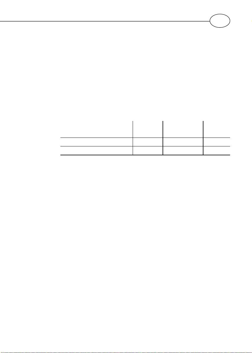
Technical data
For the technical characteristics of the appliance, please refer to the
information provided on the data plate (label located near the water inlet
and outlet pipes).
Above-sink
Above-sink
Above-sink
Under-sink
Under-sink
Model 10 15 30
Theoretical weight kg: 6,6 7,4 12,8
General remarks
This appliance is not intended for use by persons (including children) with reduced
physical, sensory or mental capabilities, or lak of experience and knowledge, unless
they have been given supervision or instruction concerning use of the appliance
by a person responsible for their safety. Children should be supervised to ensure
that they do not play with the appliance.
Local regulations may provide restrictions for installation in bathrooms.
Installation is in charge of the purchaser the manufacturer cannot be held
responsible for the damages caused by wrong installation and for not
following instructions included in this pamphlet, particularly on:
1) The electric connection has to be in compliance with the relative para-
graphe.
2) The installation has to be carried out by qualified professional.
Installation instructions
The range of the water-heaters includes models prepared for being fitted
over or under the point of use (wash-basin, sink, shower). The models to
be fitted under the point of use called “sottolavello” (”under wash-basin”).
Fastening to the wall
Fasten the supporting bracket provided to the wall using screws and
rawlplugs of suitable dimensions for the type of wall.
Hook the water heater onto the bracket and pull it dowanwards to make
sure it has been fastened correctly.
Water
Connect the water heater’s inlet and outlet with pipes or fittings that are
connection
resistant to the working pressure as well as to the temperature of the hot
water that can usually reach and exceed 80° C. We therefore advise against
the use of materials that do not resist such high temperatures. Screw a “T”
piece union to the water heater inlet pipe with the bleu collar. On one side
7

GB
of the “T” piece union, screw a valve for draining the appliance that can
only be operated with the use of a tool (B fig. 1). On the other side of the
“T” piece union screw the safety valve (A fig. 1). This should be connect
to the cold water network via flexible pipe. Also attach in the case that the
emptying tap should be opened a waste pipe to exit C fig. 1.
A slight drip during the heating phase is quite normal; for this very reason,
we recommend you connect this drain, leaving it always open, to a drain
pipe installed inclined continuously downwards and place without
condensation. In case of pressure on the network close to the calibration-
values of the valve, it is needed to apply a pressure-reducer as far as
possibile from the boiler.
“Free drain”
For this type of installation it is needed to utilise suitable watertaps and
connection
carry out the connection as shown in the scheme fig. 2. With this method,
the water heater can operate at any mains pressure. Do not connect the
tap on the outlet pipe since this acts as a blend pipe.
Electrical
The feeding cable (type H05 V V - F 3x1.5 diameter 8.5 mm) is to be
connection
inserted in the proper hole F fig. 3 situated in the back of the apparatus
and slide it until ir reaches the housing slot V fig. 5 near the thermostat.
To disconnet the unit from the network use a bipolar switch conform to
CEI-EN standards (contact opening at least 3 mm, better if equipped with
fuses).
The electric connection is carried out directly to the clamps M fig. 5 of the
thermostat.
The appliance must be earthed and the earth cable (which must be yellow-
green and longer than that of the phases) is fixed to the terminal T fig. 5
marked by the symbol . Before starting it working, make sure that the
network tension is in compliance with the rating values of the apparatus.
If the appliance has no power supply cable, it can be connected to
the mains with a rigid tube or a flexible cable.
Putting it
Filling the boiler with the network water is the last thing to do, before
into service
connecting the tension. It is carried out by opening the tap of the central
and testing
domestic system and hot-water system till all the air from the boiler is out.
Check visually for any leaks; may sure that the position of the autoclave
flange is centred; eventually tighten with moderation the nut E fig. 5, so
connect it, move the switch F from 0 position to the I position fig. 7.
For models which are not fitted with a switch, provide electrical power by
turning the control knob in a clockwise direction.
Maintenance instructions
Incidental
All intervention ad maintenance operations must be performed by qualified
replacement
personnel only.
of particulars
Before calling the Technical Assistance service in the event of a suspected
malfunction, you should first check whether this is due to other causes,
such as (for example) a temporary power failure or a water shortage.
Before starting any maintenance work, disconnect the apparatus from the
electricity network.
Before working on the heating element welded to the flange, remember
to empty the appliance. To do this, shut the main tap, open the drain of
the safety valve and turn on the water tap to empty the inlet pipe.
Disconnect the X and Y terminals and the earth one T unscrewing the nut
8

GB
E fig. 5; take off the bracket close-flange S, then with nippers hold the Z
nut and then press on the flange G into the inside.
At this moment the flange can be taken away with a semicircular movement
as shown on fig. 4. During the reassembling phase, fig. 4, make sure that
the positions of the gasket, of the flange are the original ones referred to
in fig. 5.
Periodic
In order to obtain performance from the appliance it is advisable to scale
maintenance
off the heating element R fig. 6 about every two years, depending from
the hardness of the water.
If one does not wish to use suitable acids, the operation can be carried
out by crumbling the limestone crust making sure not to damage the
covering of the heating element.
The magnesium anode, N fig. 6 must be replaced every two years.
To remove it dismantle the heating element and unscrew the anode from
the bracket.
Bipolar
In case of abnormal water heating, a thermic safety switch, according to
safety
the CEI-EN regulations, breaks the circuit in both feeding fases to the
reactivation
heating element; in this case it is better to call the Technical Assistance.
Safety valve
In those moels equipped with a safety valve with a lever, the latter can be
used, by lifting it up, to:
- empty out the appliance, if necessary
- check on a regular basis (every month) that the valve is operating
correctly.
Useful hints
1) If hot water does not come out from the taps, before calling the Technical
(user)
Assistance, make sure that the water and electric links are as specified
in the relative paragraphs, or make sure of the continuity of the phases
between the clamps and the relative fastons on the thermostat, after
taking it to pieces. In a negative case one can presume the intervention
of the bipolar safety (call the Technical Assistance).
2) If the warning light does not light up, but hot water still comes from the
apparatus, possibly it is only a faulty bulb.
For the replacement of the warning light bulb one takes away the
thermostat (unscrewing the two fixing screws), disconnects the connection
fastons L fig. 5 and slips out the bulb P from the thermostat seat; insert
the new bulb and reassemble the thermostat.
3)For the water heater’s galvanic protection system to function properly.
The permanente hardness of the water should not be less than 12° fr.
During the normal functioning of the appliance, the connections could
become hot.
Instructions for use
Starting
As already said the starting is carried out moving the switch F fig. 7 from
position O to position I.
For models which are not fitted with a switch, provide electrical power by
turning the control knob in a clockwise direction.
The warning light remains on only during heating phase.
The thermostat will automatically disconnect the heating element when
the selected operating temperature is reached.
9
GB
Regulation of
The regulation of the temperature is carried on turning the handle M fig.
the operating
7 stationed on the front of the cap: clock wise to increase temperature,
temperature
anticlock wise to decrease it.
Position E is the ideal working temperature (55° - 60° C).
This temperature gets the optimum performance from the apparatus with
a notable saving of energy and longer life ot the water heater.
Anti-freeze
function
This appliance complies with the requirements set forth in EMC
directive 89/336/EEC concerning the electromagnetic compatibility.
WARNING! For those nations that have taken on European norm EN
1487:2000, the pressure safety device provided with the product does
not comply with national norms. According to the norm, the device
must have a maximum pressure of 0.7MPa (7 bar) and have at least:
a cut-off valve, a non-return valve, a control mechanism for the non-
return valve, a safety valve and a water pressure shut-off device.
This product confirms to EU Directive 2002/96/EC.
The symbol of the crossed waste paper basket on the appliance indicates that at the end of its working
life the product should be disposed of separately from normal domestic household rubbish, it must be
disposed of at a waste disposal centre with dedicated facilities for electric and electronic appliances or
returned to the retailer when a new replacement product is purchased.
The user is responsible for the disposal of the product at the end of its life at an appropriate waste disposal centre.
The waste disposal centre (using special treatment and recycling processes effectively dismantles and disposes of the
appliance) helps to protect the environment by recycling the material from which the product is made.
For further information about waste disposal systems visit your local waste disposal centre or the retailer from which
the product was purchased.
10
