ASRock Fatal1ty Z68 Professional Gen3: I/O Panel
I/O Panel: ASRock Fatal1ty Z68 Professional Gen3
5
Fatal1ty Z68 Professional Gen3 Series Motherboard
English
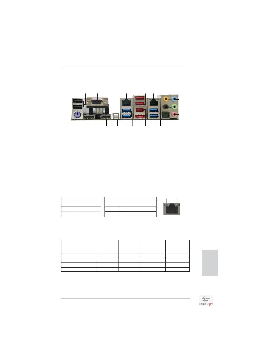
I/O Panel
* There are two LED next to the LAN port. Please refer to the table below for the LAN port LED
indications.
LAN Port LED Indications
Activity/Link LED
SPEED LED
Status Description Status Description
Off No Link Off 10Mbps connection
Blinking Data Activity Orange 100Mbps connection
On Link
Green 1Gbps connection
ACT/LINK
LED
SPEED
LED
LAN Port
5
7
8
9
10
11
12
13
4
1
2
3
14
15
16
17
18
19
6
20
**
If you use 2-channel speaker, please connect the speaker’s plug into “Front Speaker Jack”.
See the table below for connection details in accordance with the type of speaker you use.
TABLE for Audio Output Connection
Audio Output Channels Front Speaker Rear Speaker
Central / Bass
Line In or
(No. 11)
(No. 8)
(No. 7) Side Speaker
(No. 10)
2
V
-- -- --
4 V
V
--
--
6
V
V V --
8
V
V V V
1
USB 2.0 Ports (USB01) ** 11 Front Speaker (Lime)
2
VGA/D-Sub Port
12 Microphone (Pink)
* 3
LAN RJ-45 Port
13 USB 3.0 Ports (USB23)
4
Fatal1ty Mouse Port (USB2)
14 IEEE 1394 Port (IEEE 1394)
5
USB 2.0 Port (USB3) *** 15 eSATA3 Connector
* 6
LAN RJ-45 Port
16 USB 3.0 Ports (USB01)
7
Central / Bass (Orange)
17 Clear CMOS Switch (CLRCBTN)
8
Rear Speaker (Black) **** 18 VGA/HDMI Port (HDMI2)
9
Optical SPDIF Out Port **** 19 VGA/HDMI Port (HDMI1)
10
Line In (Light Blue)
20 PS/2 Keyboard Port (Purple)
6
Fatal1ty Z68 Professional Gen3 Series Motherboard
To enable Multi-Streaming function, you need to connect a front panel audio cable to the front
panel audio header. After restarting your computer, you will
fi
nd “Mixer” tool on your system.
Please select “Mixer ToolBox” , click “Enable playback multi-streaming”, and click
“ok”. Choose “2CH”, “4CH”, “6CH”, or “8CH” and then you are allowed to select “Realtek HDA
Primary output” to use Rear Speaker, Central/Bass, and Front Speaker, or select “Realtek
HDA Audio 2nd output” to use front panel audio.
*** eSATA3 connector supports SATA Gen3 in cable 1M.
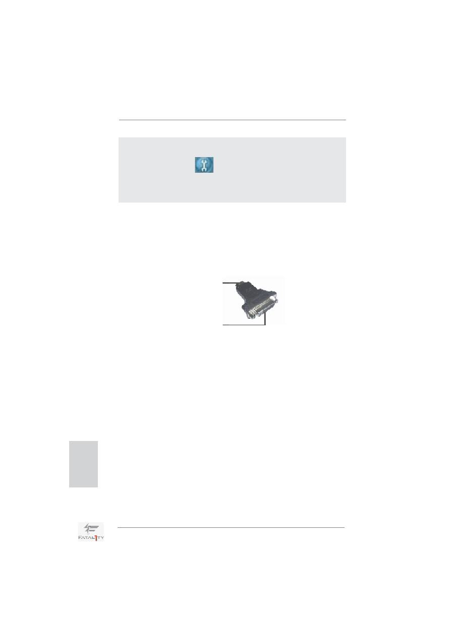
**** HDMI is backwards compatible with DVI. VGA/HDMI port can function similarly as DVI port
by applying the bundled HDMI to DVI adapter. Please connect the HDMI to DVI adapter to
the VGA/HDMI port on the I/O panel and then connect the DVI-D monitor cable to the VGA/
DVI-D connector on the adpater.
For PS/2 Keyboard users, it is recommended to apply the adapter on HDMI2. If HDMI1 is
connected to the adapter, please use USB Keyboard and do not use the PS/2 Keyboard
port. For the other users, apply it either on HDMI1 or HDMI2.
HDMI to DVI adapter
HDMI connector
DVI connector
English
Оглавление
- Motherboard Layout
- I/O Panel
- 1. Introduction
- 2. Installation
- 3. BIOS Information
- 1. Einführung
- 2. Installation
- 3. BIOS-Information
- 1. Introduction
- 2. Installation
- 3. Informations sur le BIOS
- 1. Introduzione
- 2. Installazione
- 3. Informazioni sul BIOS
- 1. Introducción
- 2. Instalación
- 3. BIOS Información
- 1. Введение
- 2. Установка
- 3.
- 1. Giri ş
- 2. Takma
- 3. BIOS Bilgileri
- 1. 제품소개
- 2. 설치하기
- 3. 시스템 바이오스 정보
- 1. 主板簡介
- 2. 主板安裝
- 3. BIOS 信息
- 1. 主機板簡介
- 2. 主機板安裝
- 3. BIOS 訊息
- Installing OS on a HDD Larger Than 2TB
- Note
