Gigabyte GA-MA790FXT-UD5P: Chapter 4 Unique Features
Chapter 4 Unique Features: Gigabyte GA-MA790FXT-UD5P
Chapter 4 Unique Features
4-1 Xpress Recovery2
Xpress Recovery2 is a utility that allows you to quickly compress and
back up your system data and perform restoration of it. Supporting
NTFS, FAT32, and FAT16 file systems, Xpress Recovery2 can back
up data on PATA and SATA hard drives and restore it.
Before You Begin:
• Xpress Recovery2 will check the first physical hard drive* for the operating system. Xpress
Recovery2 can only back up/restore the first physical hard drive that has the operating system
installed.
• As Xpress Recovery2 will save the backup file at the end of the hard drive, make sure to leave
enough unallocated space in advanced (10 GB or more is recommended; actual size require-
ments vary, depending on the amount of data).
• It is recommended to back up your system soon after the operating system and drivers are
installed.
• The amount of data and hard drive access speed may affect the speed at which the data is backed
up/restored.
• It takes longer to back up a hard drive than to restore it.
System Requirements:
• At least 512 MB of system memory
• VESA compatible graphics card
®
®
• Windows
XP with SP1 or later, Windows
Vista
• Xpress Recovery and Xpress Recovery2 are different utilities. For example, a backup file created with Xpress
Recovery cannot be restored using Xpress Recovery2.
• USB hard drives are not supported.
• Hard drives in RAID/AHCI mode are not supported.
Installation and Configuration
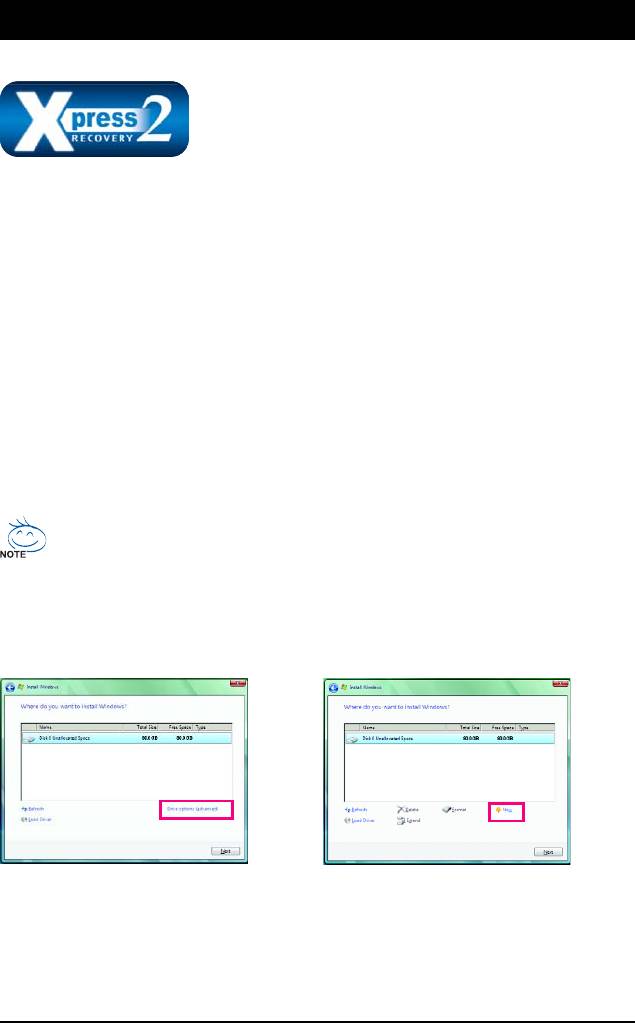
Turn on your system to boot from the Windows Vista setup disk.
A. Installing Windows Vista and Partitioning the Hard Drive
Step 1:
Step 2:
Click Drive options.
Click New.
"*" Xpress Recovery2 checks the first physical hard drive in the following sequence: The first PATA IDE connector,
the second PATA IDE connector, the first SATA connector, the second SATA connector and so forth. For
example, when hard drives are attached to the first IDE and the first SATA connectors, the hard drive on the first
IDE connector is the first physical drive. When hard drives are attached to the first and second SATA connectors,
the hard drive on the first SATA connector is the first physical drive.
Unique Features- 67 -
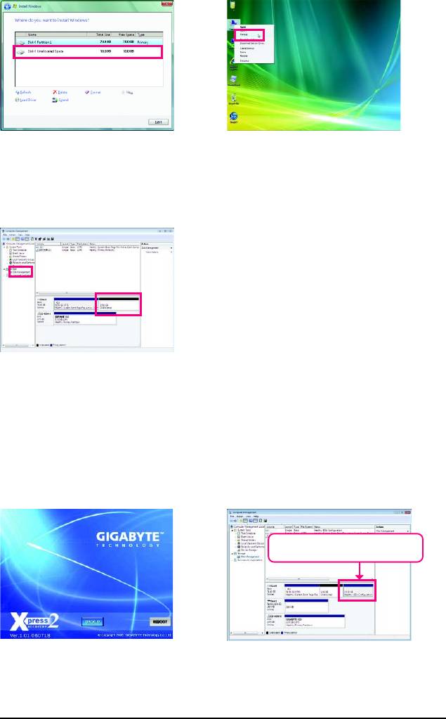
Step 3:
Step 4:
When partitioning your hard drive, make sure
After the operating system is installed, right-
to leave unallocated space (10 GB or more is
click the Computer icon on your desktop
recommended; actual size requirements vary,
and select Manage. Go to Disk Management
depending on the amount of data) and begin the
to check disk allocation.
installation of the operating system.
Step 5:
Xpress Recovery2 will save the backup file to the
unallocated space (black stripe along the top). Please
note that if there is no enough unallocated space, Xpress
Recovery2 cannot save the backup file.
B. Accessing Xpress Recovery2
1. Boot from the motherboard driver disk to access Xpress Recovery2 for the first time. When you see
the following message: Press any key to startup Xpress Recovery2 , press
any key to enter Xpress Recovery2.
2. After you use the backup function in Xpress Recovery2 for the first time, Xpress Recovery2 will stay
permanent in your hard drive. If you wish to enter Xpress Recovery2 later, simply press <F9> during
the POST.
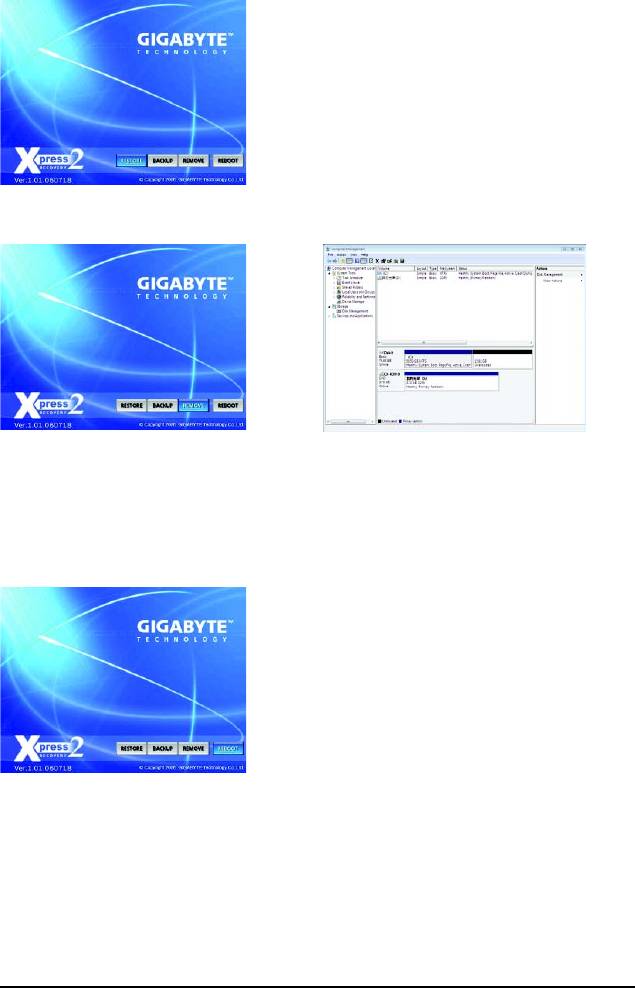
C. Using the Backup Function in Xpress Recovery2
Xpress Recovery2 will automatically create a
new partition to store the backup image file.
Step 1:
Step 2:
Select BACKUP to start backing up your hard
When finished, go to Disk Management to
drive data.
check disk allocation.
GA-MA790FXT-UD5P Motherboard - 68 -
D. Using the Restore Function in Xpress Recovery2
Select RESTORE to restore the backup to your hard
drive in case the system breaks down. The RESTORE
option will not be present if no backup is created before.
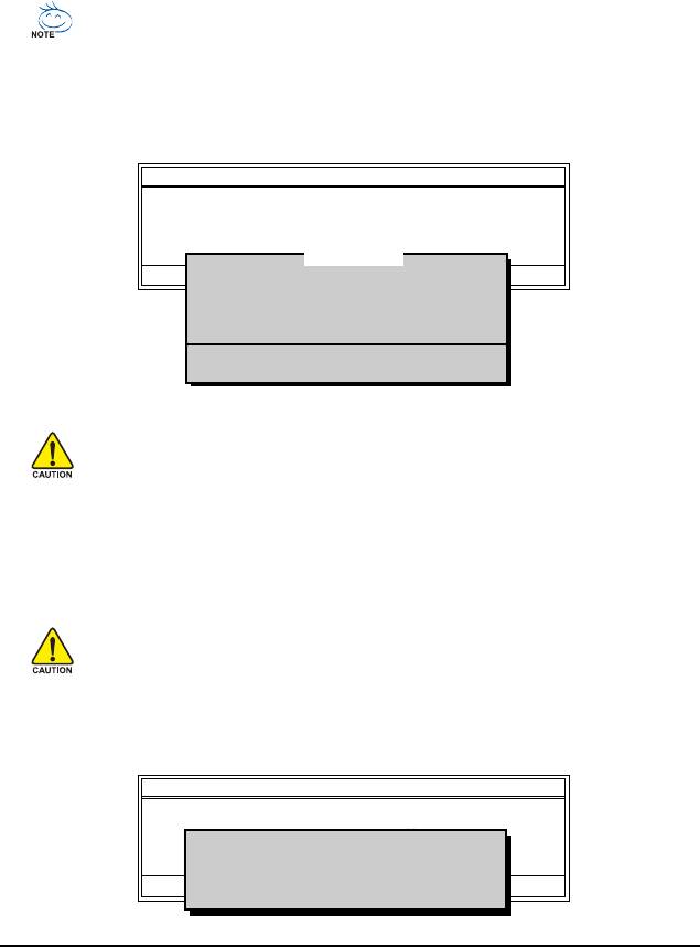
E. Removing the Backup
Step 1:
Step 2:
If you wish to remove the backup file, select
After the backup file is removed, no backup
REMOVE.
image file will be present in Disk Management
and hard drive space will be freed up.
F. Exiting Xpress Recovery2
Select REBOOT to exit Xpress Recovery2.
Unique Features- 69 -

4-2 BIOS Update Utilities
TM
TM
GIGABYTE motherboards provide two unique BIOS update tools, Q-Flash
and @BIOS
. GIGABYTE
Q-Flash and @BIOS are easy-to-use and allow you to update the BIOS without the need to enter MS-
TM
DOS mode. Additionally, this motherboard features the DualBIOS
design, which enhances protection
for the safety and stability of your computer by adding one more physical BIOS chip.
TM
What is DualBIOS
?
Motherboards that support DualBIOS have two BIOS onboard, a main BIOS
and a backup BIOS. Normally, the system works on the main BIOS.
However, if the main BIOS is corrupted or damaged, the backup BIOS will take over on the next system
boot and copy the BIOS file to the main BIOS to ensure normal system operation. For the sake of
system safety, users cannot update the backup BIOS manually.
TM
What is Q-Flash
?
With Q-Flash you can update the system BIOS without having to enter
operating systems like MS-DOS or Window first. Embedded in the BIOS, the
Q-Flash tool frees you from the hassles of going through complicated BIOS flashing process.
TM
What is @BIOS
?
@BIOS allows you to update the system BIOS while in the Windows
environment. @BIOS will download the latest BIOS file from the nearest
@BIOS server site and update the BIOS.
4-2-1 Updating the BIOS with the Q-Flash Utility
A. Before You Begin:
1. From GIGABYTE's website, download the latest compressed BIOS update file that matches your
motherboard model.
2. Extract the file and save the new BIOS file (e.g. M79XTUD5.F1) to your floppy disk, USB flash
drive, or hard drive. Note: The USB flash drive or hard drive must use FAT32/16/12 file system.
3. Restart the system. During the POST, press the <End> key to enter Q-Flash. Note: You can
access Q-Flash by either pressing the <End> key during the POST or pressing the <F8> key in
BIOS Setup. However, if the BIOS update file is saved to a hard drive in RAID/AHCI mode or a hard
drive attached to an independent IDE/SATA controller, use the <End> key during the POST to
access Q-Flash.
Because BIOS flashing is potentially risky, please do it with caution. Inadequate BIOS
flashing may result in system malfunction.
GA-MA790FXT-UD5P Motherboard - 70 -
B. Updating the BIOS
When updating the BIOS, choose the location where the BIOS file is saved. The follow procedure
assumes that you save the BIOS file to a floppy disk.
Step 1:
1. Insert the floppy disk containing the BIOS file into the floppy disk drive. In the main menu of
Q-Flash, use the up or down arrow key to select Update BIOS from Drive and press <Enter>.
• The Save Main BIOS to Drive option allows you to save the current BIOS file.
• Q-Flash only supports USB flash drive or hard drives using FAT32/16/12 file system.
• If the BIOS update file is saved to a hard drive in RAID/AHCI mode or a hard drive
attached to an independent IDE/SATA controller, use the <End> key during the POST to
access Q-Flash.
2. Select Floppy A and press <Enter>.
Q-Flash Utility v2.08
Flash Type/Size.................................MXIC 25L8005 1M
Keep DMI Data Enable
Update BIOS from Drive
Save BIOS to Drive
0 file(s) found
Enter : Run :Move ESC:Reset F10:Power Off
Floppy A <Drive>
HDD 0-0 <Drive>
Total size : 0 Free size : 0
3. Select the BIOS update file and press <Enter>.
Make sure the BIOS update file matches your motherboard model.
Step 2:
The process of the system reading the BIOS file from the floppy disk is displayed on the screen. When
the message "Are you sure to update BIOS?" appears, press <Enter> to begin the BIOS update. The
monitor will display the update process.
• Do not turn off or restart the system when the system is reading/updating the BIOS.
• Do not remove the floppy disk, USB flash drive, or hard drive when the system is
updating the BIOS.
Step 3:
When the update process is complete, press any key to return to the main menu.
Q-Flash Utility v2.08
Flash Type/Size.................................MXIC 25L8005 1M
Keep DMI Data Enable
Update BIOS from Drive
!! Copy BIOS completed - Pass !!
Save BIOS to Drive
Enter : Run :Move ESC:Reset F10:Power Off
Please press any key to continue
Unique Features- 71 -

Step 4:
Press <Esc> and then <Enter> to exit Q-Flash and reboot the system. As the system boots, you should
see the new BIOS version is present on the POST screen.
Step 5:
During the POST, press <Delete> to enter BIOS Setup. Select Load Optimized Defaults and press
<Enter> to load BIOS defaults. System will re-detect all peripherals devices after a BIOS update, so we
recommend that you reload BIOS defaults.
CMOS Setup Utility-Copyright (C) 1984-2009 Award Software
MB Intelligent Tweaker(M.I.T.)
Load Fail-Safe Defaults
Standard CMOS Features
Load Optimized Defaults
Advanced BIOS Features
Set Supervisor Password
Integrated Peripherals
Set User Password
Load Optimized Defaults (Y/N)? Y
Power Management Setup
Save & Exit Setup
PC Health Status
Exit Without Saving
ESC: Quit : Select Item F11: Save CMOS to BIOS
F8: Q-Flash F10: Save & Exit Setup F12: Load CMOS from BIOS
Load Optimized Defaults
Press <Y> to load BIOS defaults
Step 6:
Select Save & Exit Setup and then press <Y> to save settings to CMOS and exit BIOS Setup. The
procedure is complete after the system restarts.
GA-MA790FXT-UD5P Motherboard - 72 -
4-2-2 Updating the BIOS with the @BIOS Utility
A. Before You Begin:
1. In Windows, close all applications and TSR (Terminate and Stay Resident) programs. This helps
prevent unexpected failures when performing a BIOS update.
2. During the BIOS update process, ensure the Internet connection is stable and do NOT interrupt the
Internet connection (for example, avoid a power loss or switching off the Internet). Failure to do so
may result in a corrupted BIOS or a system that is unable to start.
3. Do not use the G.O.M. (GIGABYTE Online Management) function when using @BIOS.
4. GIGABYTE product warranty does not cover any BIOS damage or system failure resulting from an
inadequate BIOS flashing.
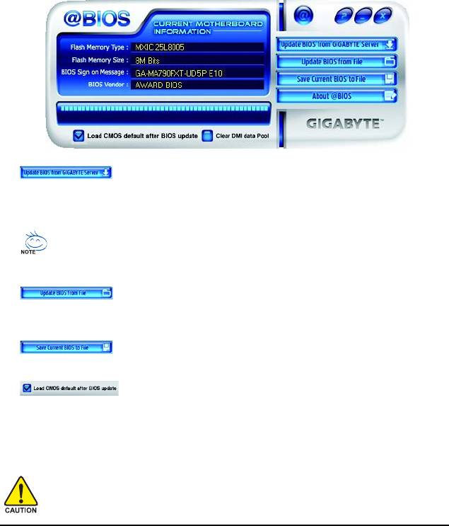
B. Using @BIOS:
1. Update the BIOS Using the Internet Update Function:
Click Update BIOS from GIGABYTE Server, select the @BIOS server site closest to your
location and then download the BIOS file that matches your motherboard model. Follow the on-
screen instructions to complete.
If the BIOS update file for your motherboard is not present on the @BIOS server site, please
manually download the BIOS update file from GIGABYTE's website and follow the instruc-
tions in "Update the BIOS without Using the Internet Update Function" below.
2. Update the BIOS without Using the Internet Update Function:
Click Update BIOS from File, then select the location where you save the BIOS update file
obtained from the Internet or through other source. Follow the on-screen instructions to complete.
3. Save Current BIOS to File:
Click Save Current BIOS to save the current BIOS file.
4. Load BIOS defaults after BIOS Update:
Select the Load CMOS default after BIOS update check box and then the system will automatically
load BIOS defaults after BIOS update and after the system restarts.
C. After Updating the BIOS:
Restart your system after updating the BIOS.
Make sure that the BIOS file to be flashed matches your motherboard model. Updating the
BIOS with an incorrect BIOS file could cause your system not to boot.
Unique Features- 73 -
4-3 EasyTune 6
GIGABYTE's EasyTune 6 is a simple and easy-to-use interface that allows users to fine-tune their
system settings or do overclock/overvoltage in Windows environment. The user-friendly EasyTune 6
interface also includes tabbed pages for CPU and memory information, lettings users read their system-
related information without the need to install additional software.
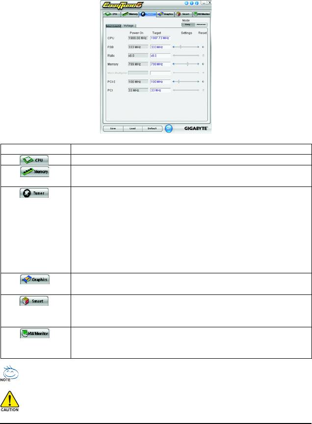
The EasyTune 6 Interface
Tabs Information
Tab Function
The CPU tab provides information on the installed CPU and motherboard.
The Memory tab provides information on the installed memory module(s).
You can select memory module on a specific slot to see its information.
The Tuner tab allows you to change system clock settings and voltages.
• Easy mode allows you to adjust the CPU FSB only.
• Advanced mode allows you to individually change system clock
settings and voltages settings using the sliders.
• Save allows you to save the current settings to a new profile (.txt file).
• Load allows you to load previous settings from a profile.
After making changes, be sure to click Set for these changes to take effect
or click Default to restore to default values.
The Graphics tab allows you to change the core clock and memory clock
for your ATI or NVIDIA graphics card.
The Smart tab allows you to specify a C.I.A.2 level and a Smart Fan mode.
Smart Fan Advance Mode allows the CPU fan speed to be changed
linearly based on the CPU temperature thresholds you set.
The HW Monitor tab allows you to monitor hardware temperature, volt-
age and fan speed and set temperature/fan speed alarm. You can choose
the alert sound from the buzzer or use your own sound file (.wav file).
Available functions in EasyTune 6 may differ by motherboard model. Grayed-out area(s) indicates that the item is not
configurable or the function is not supported.
Incorrectly doing overclock/overvoltage may result in damage to the hardware components such as CPU, chipset, and
memory and reduce the useful life of these components. Before you do the overclock/overvoltage, make sure that you
fully know each function of EasyTune 6, or system instability or other unexpected results may occur.
GA-MA790FXT-UD5P Motherboard - 74 -

4-4 Easy Energy Saver
GIGABYTE Easy Energy Saver
is a revolutionary technology that delivers unparalleled power savings
with a click of the button. Featuring an advanced proprietary software design, GIGABYTE Easy Energy
Saver is able to provide exceptional power savings and enhanced power efficiency without sacrificing
computing performance.
The Easy Energy Saver Interface
A. Meter Mode
In Meter Mode, GIGABYTE Easy Energy Saver shows how much power they have saved in a set
period of time.
Meter Mode - Button Information Table
Button Description
1 Easy Energy Saver On/Off Switch (Default: Off)
(Note 1)
2 Dynamic CPU Frequency Function On/Off Switch (Default: Off)
3 CPU Throttling Display
4 CPU Voltage Display
(Note 2)
5 3-Level CPU Voltage Switch (Default:1)
6 Current CPU Power Consumption
7 Meter Time
8 Power Saving (Calculate power savings based on time)
9 Meter/Timer Reset Switch
10 Meter Mode Switch
11 Total Mode Switch
12 Close (Application will enter Stealth Mode)
13 Minimize (Application will continue to run in taskbar)
14 INFO/Help
15 Live Utility Update (Check for the latest utility version)
• The above data is for reference only. Actual performance may vary depending on motherboard model.
• CPU Power and Power Scores are for reference only. Actual results may vary based on testing method.
Unique Features- 75 -

B. Total Mode
In Total Mode, users are able to see how much total power savings they have accumulated in a set
(Note 3)
period of time since activating Easy Energy Saver for the first time
.
Total Mode - Button Information Table
Button Description
1 Easy Energy Saver On/Off Switch (Default: Off)
2 Dynamic CPU Frequency Function On/Off Switch (Default: Off)
3 CPU Throttling Display
4 CPU Voltage Display
(Note 2)
5 3-Level CPU Voltage Switch (Default:1)
6 Current CPU Power Consumption
7 Time/Date Easy Energy Saver Enabled
(Note 4)
8 Total Power Savings (Total power saving with Easy Energy Saver enabled)
9 Meter Mode Switch
10 Total Mode Switch
11 Close (Application will enter Stealth Mode)
12 Minimize (Application will continue to run in taskbar)
13 INFO/Help
14 Live Utility Update (Check for the latest utility version)
C. Stealth Mode
In Stealth Mode, the system continues to work with the user-defined power saving settings, even after
the system is restarted. Re-enter the application only if you want to make any changes or completely
close the application.
(Note 1) Maximize system power saving with Dynamic CPU Frequency Function; system
performance may be affected.
(Note 2) 1: Normal Power Saving (default); 2: Advanced Power Saving; 3: Extreme Power Saving.
(Note 3) The total amount of power saved will be recorded until re-activated when only the Easy
Energy Saver is under the enable status, and power savings meter is unable to reset to zero.
(Note 4) Easy Energy Saver Meter will automatically reset when the total power saving reaches
99999999 Watts.
GA-MA790FXT-UD5P Motherboard - 76 -
4-5 Q-Share
Q-Share is an easy and convenient data sharing tool. After configuring your LAN connection settings
and Q-Share, you are able to share your data with computers on the same network, making full use of
Internet resources.
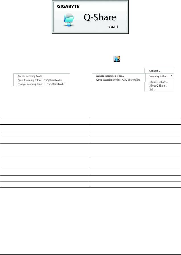
Directions for using Q-Share
After installing Q-Share from the motherboard driver disk, go to Start>All Programs>GIGABYTE>
Q-Share.exe to launch the Q-Share tool. Find the Q-Share icon in your system tray and right-click
on this icon to configure the data sharing settings.
Figure 2. Data Sharing EnabledFigure 1. Data Sharing Disabled
Options Descriptions
Option Description
Connect ... Displays the computers with data sharing enabled
Enable Incoming Folder ... Enables data sharing
Disable Incoming Folder ... Disables data sharing
Open Incoming Folder : Accesses the shared data folder
C:\Q-ShareFolder
(Note)
Change Incoming Folder : Changes the data folder to be shared
C:\Q-ShareFolder
Update Q-Share ... Updates Q-Share online
About Q-Share ... Displays the current Q-Share version
Exit... Exits Q-Share
(Note) This option is available only when data sharing is NOT enabled.
Unique Features- 77 -
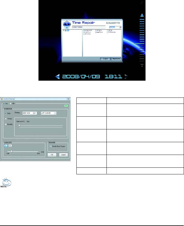
4-6 Time Repair
Based on the Microsoft Volume Shadow Copy Services technology, Time Repair allows you to
quickly back up and restore your system data in the Windows Vista operating system. Time Repair
supports NTFS file system and can restore system data on PATA and SATA hard drives.
System Restore
Choose a system restore point using the navigation bar on the right or at the bottom of the screen to
view the system data backed up at different time. You can choose file(s)/directory(ies) and click the
Copy button to restore the file(s)/directory(ies) or click Restore to restore the entire system.
Preference Screen:
Button Function
ON Automatically creates system restore
points
OFF DO NOT automatically create system
restore points
SCHEDULE Sets a regular interval for creating
system restore points
CAPACITY Sets the percentage of hard drive space
used for saving shadow copies
TRIGGER Creates a system restore point upon the
first boot up of the day
? Displays the Time Repair help file
• The hard drive used must have more than 1 GB of capacity and over 300 MB of available space.
• Each storage volume can accommodate 64 shadow copies. When this limit is reached, the
oldest shadow copy will be deleted and unable to be restored. Shadow copies are read-only
so you cannot edit the contents of a shadow copy.
GA-MA790FXT-UD5P Motherboard - 78 -
4-7 Teaming
Dual LAN with Teaming functionality enabled on this motherboard allows two single connections to act as
one single connection for twice the transmission bandwidth, making data transmission more effective and
improving the quality of transmission of distant image(s). Fault tolerance on the dual LAN network
prevents network downtime by transferring the workload from a failed port to a working port.
• The speed of transmission is subject to the actual network environment or status even with Teaming enabled.
• To enable Teaming or Bonding (IEEE 802.3ad Link Aggregation) feature, it is required the connected network switch
or router device supports the IEEE 802.3ad LACP standard. Please refer to your network switch or router device
manual for further details.
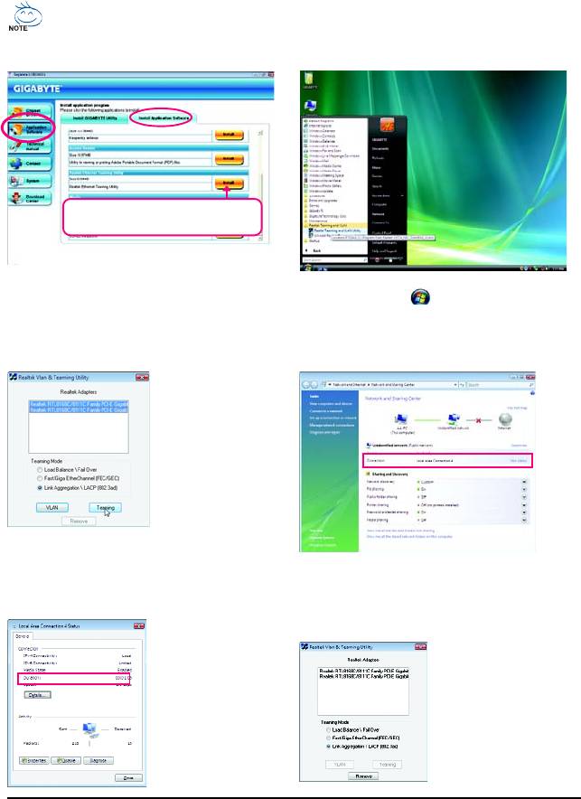
Select Realtek Ethernet Teaming Utility and
click Install.
Step 1:
Step 2:
Insert the motherboard driver disk and select Appli-
Click the Start icon . Point to All Programs,
cation Software, Install Application Software.
Realtek Teaming and VLAN, Realtek Teaming
Click Install under Realtek Ethernet Teaming Util-
and VLAN Utility to access the utility.
ity for installation. Restart your system when completed.
Step 3:
Select the two adapters
and set up the Teaming
mode based on your
hub's specifications.
Then click the Team-
ing button. (Two dia-
log boxes will appear
during the setup
process, click OK to continue). When the Create
Virtual Adapter For Teaming Complete dialog
Step 4:
box appears, click OK to complete.
After the Teaming is created, you will see only
one connection in Network and Sharing Center.
Step 5:
Removing the Existing Teaming:
Click View status in
If you want to remove the
Network and Sharing
existing Teaming, ac-
Center and you will see
cess the Realtek Vlan
the connection speed is
& Teaming Utility and
2.0 Gbps.
click the Remove button.
Unique Features- 79 -

GA-MA790FXT-UD5P Motherboard - 80 -


