Gigabyte GA-MA790FXT-UD5P: Chapter 5 Appendix
Chapter 5 Appendix: Gigabyte GA-MA790FXT-UD5P

Chapter 5 Appendix
5-1 Configuring SATA Hard Drive(s)
To configure SATA hard drive(s), follow the steps below:
A. Install SATA hard drive(s) in your computer.
B. Configure SATA controller mode in BIOS Setup.
(Note 1)(Note 2)
C. Configure a RAID array in RAID BIOS.
(Note 2)
D. Make a floppy disk containing the SATA RAID/AHCI driver for Windows XP.
(Note 2)
E. Install the SATA RAID/AHCI driver
and operating system.
Before you begin
Please prepare:
• At least two SATA hard drives (to ensure optimal performance, it is recommended that you use
two hard drives with identical model and capacity). If you do not want to create RAID, you may
prepare only one hard drive.
• An empty formatted floppy disk.
• Windows Vista/XP setup disk.
• Motherboard driver disk.
5-1-1 Configuring AMD SB750 SATA Controller
A. Installing SATA hard drive(s) in your computer
Attach one end of the SATA signal cable to the rear of the SATA hard drive and the other end to available
SATA port on the motherboard. If there is more than one SATA controller on your motherboard, refer to
"Chapter 1," "Hardware Installation," to identify the SATA controller for the SATA port. (For example, on
this motherboard, the SATA2_0, SATA2_1, SATA2_2, SATA2_3, SATA2_4 and SATA2_5 ports are
supported by SB750 South Bridge.) Then connect the power connector from your power supply to the
hard drive.
(Note 1) Skip this step if you do not want to create RAID array on the SATA controller.
(Note 2) Skip this step if you configure the hard drives attached to the GIGABYTE SATA2/JMB322 SATA
controller to RAID mode.
Appendix- 81 -
B. Configuring SATA controller mode in BIOS Setup
Make sure to configure the SATA controller mode correctly in system BIOS Setup .
Step 1:
Turn on your computer and press <Delete> to enter BIOS Setup during the POST (Power-On Self-Test).
Ensure OnChip SATA Controller is enabled under Integrated Peripherals. To enable RAID for the
SATA2_0/1/2/3 connectors, set OnChip SATA Type to RAID. To enable RAID for the SATA2_4/5
connectors, set OnChip SATA Type to RAID and set OnChip SATA Port4/5 Type to As SATA Type
(Figure 1).
CMOS Setup Utility-Copyright (C) 1984-2009 Award Software
Integrated Peripherals
OnChip IDE Channel [Enabled]
Item Help
OnChip SATA Controller [Enabled]
Menu Level
OnChip SATA Type [RAID]
OnChip SATA Port4/5 Type [As SATA Type]
Onboard SATA/IDE Device [Enabled]
Onboard SATA/IDE Ctrl Mode [IDE]
Smart Backup [Press Enter]
Onboard Audio Function [Enabled]
Onboard LAN device [Press Enter]
Onboard 1394 Function [Enabled]
OnChip USB Controller [Enabled]
USB EHCI Controller [Enabled]
USB Keyboard Support [Disabled]
USB Mouse Support [Disabled]
Legacy USB storage detect [Enabled]
Onboard Serial Port 1 [3F8/IRQ4]
Onboard Parallel Port [378/IRQ7]
Parallel Port Mode [SPP]
x ECP Mode Use DMA 3
: Move Enter: Select +/-/PU/PD: Value F10: Save ESC: Exit F1: General Help
F5: Previous Values F6: Fail-Safe Defaults F7: Optimized Defaults
Figure 1
Step 2:
Save changes and exit BIOS Setup.
The BIOS Setup menus described in this section may differ from the exact settings for your
motherboard. The actual BIOS Setup menu options you will see shall depend on the motherboard
you have and the BIOS version.
GA-MA790FXT-UD5P Motherboard - 82 -

C. Configuring RAID set in RAID BIOS
Enter the RAID BIOS setup utility to configure a RAID array. Skip this step if you do not want to create
RAID.
Step 1:
After the POST memory test begins and before the operating system boot begins, look for a message
which says "Press <Ctrl-F> to enter FastBuild (tm) Utility" (Figure 2). Hit the <Ctrl>+<F> key to enter the
RAID BIOS setup utility.
RAID Option ROM Version 3.0.1540.33
(c) 2008 Advanced Micro Devices, Inc. All rights reserved.
No Array is defined..
Press <Ctrl-F> to enter FastBuild (tm) Utility...
Figure 2
Step 2:
Main Menu
This is the first option screen when you enter the BIOS RAID Setup utility. (Figure 3).
To view the disk drives assigned to arrays, press <1> to enter the View Drive Assignments window.
To create an array, press <2> to enter the Define LD window.
To delete an array, press <3> to enter the Delete LD window.
To view controller settings, press <4> to enter the Controller Configuration window.
FastBuild (tm) Utility (c) 2008 Advanced Micro Devices, Inc.
[ Main Menu ]
View Drive Assignments...........................[ 1 ]
Define LD..................................................[ 2 ]
Delete LD..................................................[ 3 ]
Controller Configuration............................[ 4 ]
[ Keys Available ]
Press 1..4 to Select Option [ESC] Exit
Figure 3
Appendix- 83 -
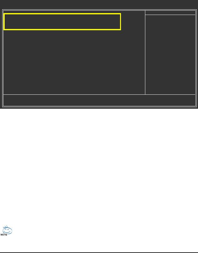
Create Arrays Manually
To create a new array, press <2> to enter the Define LD window (Figure 4). The Define LD selection
from the Main Menu allows users to begin the process of manually defining the drive elements and
RAID levels for one or multiple disk arrays.
FastBuild (tm) Utility (c) 2008 Advanced Micro Devices, Inc.
[ Define LD Menu ]
LD No RAID Mode Total Drv Capacity (GB) Status
LD 1 ---- ---- ----- ----
LD 2 ---- ---- ----- ----
LD 3 ---- ---- ----- ----
LD 4 ---- ---- ----- ----
LD 5 ---- ---- ----- ----
LD 6 ---- ---- ----- ----
LD 7 ---- ---- ----- ----
LD 8 ---- ---- ----- ----
LD 9 ---- ---- ----- ----
LD 10 ---- ---- ----- ----
[ Keys Available ]
[ ] Up [] Down [ESC] Exit [Enter] Select
Figure 4
In Figure 4, use the up or down arrow key to move to a logical disk set and press <Enter> to enter the
RAID configuration menu (Figure 5).
FastBuild (tm) Utility (c) 2008 Advanced Micro Devices, Inc.
[ Define LD Menu ]
LD No RAID Mode Total Drv
LD 1 RAID 0 0
Stripe Block: 64 KB Fast Init: ON
Gigabyte Boundary: ON Cache Mode: WriteThru
[ Drives Assignments ]
Channel:ID Drive Model Capabilities Capacity (GB) Assignment
1:Mas WDC WD800JD-22LSA0 SATA 3G 79.89 N
2:Mas WDC WD800JD-22LSA0 SATA 3G 80.02 N
[ Keys Available ]
[ ] Up [] Down [ESC] Exit [Space] Change [Ctrl-Y] Save [PgUp/Dn] Page Change
Figure 5
GA-MA790FXT-UD5P Motherboard - 84 -

In the following procedure, we'll create RAID 0 as an example.
1. Under the RAID Mode section, press the <SPACE> key to select RAID 0.
2. Set the Stripe Block size. 64 KB is the default.
3. Under the Drives Assignments section, press the up or down arrow key to highlight a drive.
4. Press the <SPACE> key or <Y>to change the Assignment option to Y. This action adds the drive
to the disk array. The Total Drv section will show the number of disks assigned.
5. Press <Ctrl>+<Y> keys to save the information. The window below will appear.
Fast Initialization option has been selected
It will erase the MBR data of the disk.
<Press Ctrl-Y key if you are sure to erase it>
<Press any other key to ignore this option>
Figure 6
6. Press <Ctrl>+<Y> to clear the MBR or press other keys to ignore this option. Then, the window
below will appear.
Press Ctrl-Y to Modify Array Capacity or press any
other key to use maximum capacity...
Figure 7
7. Press <Ctrl>+<Y> to set the capacity of the RAID array or press other keys to set the array to its
maximum capacity.
8. After the creation is complete, the screen will return to Define LD Menu where you will see the
newly-created array.
9. Press <Esc> to return to Main Menu and press <Esc> again if you want to exit the RAID BIOS
utility.
View Drive Assignments
The View Drive Assignments option in the Main Menu displays whether the attached hard drives are
assigned to a disk array or are unassigned. Under the Assignment column, drives are labeled with
their assigned disk array or shown as Free if unassigned.
FastBuild (tm) Utility (c) 2008 Advanced Micro Devices, Inc.
[ View Drives Assignments ]
Channel:ID Drive Model Capabilities Capacity (GB) Assignment
1:Mas WDC WD800JD-22LSA0 SATA 3G 79.89
Extent 1 79.82 LD 1-1
2:Mas WDC WD800JD-22LSA0 SATA 3G 80.2
Extent 1 80.02 LD 1-2
[ Keys Available ]
[ ] Up [] Down [ESC] Exit [Ctrl+H] Secure Erase [PgUp/Dn] Page Change
Figure 8
Appendix- 85 -
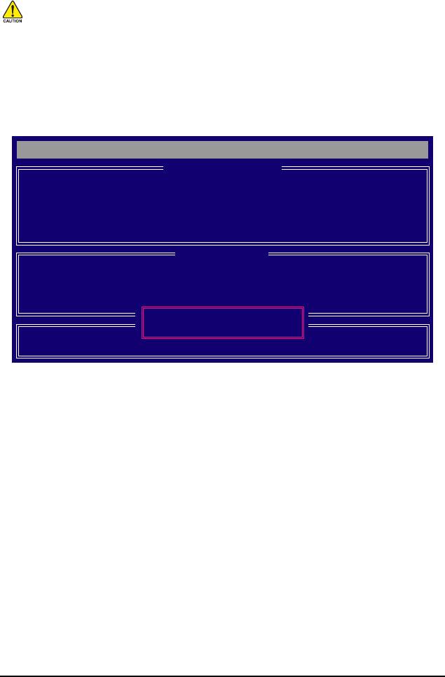
Delete an Array
The Delete Array menu option allows for deletion of disk array assignments.
Deleting an existing disk array could result in loss of data. Record all array information including
the array type, the disk members, and stripe block size in case you wish to undo a deletion.
1. To delete an array, press <3> in the Main Menu to enter the Delete LD Menu. Then highlight the
array you wish to delete and press the <Delete> key or the <Alt>+<D> keys.
2. The View LD Definition Menu will appear (as shown in Figure 9) showing which drives are
assigned to this array. Press <Ctrl>+<Y> if you are sure to delete the array or other keys to abort.
3. When the array is deleted, the screen will return to Delete LD Menu. Press <Esc>to return to
Main Menu.
FastBuild (tm) Utility (c) 2008 Advanced Micro Devices, Inc.
[ View LD Definition Menu ]
LD No RAID Mode Total Drv Capacity (GB) Status
LD 1 RAID 0 2 157.99 Functional
Stripe Block: 64KB Cache Mode: WriteThru
[ Drives Assignments ]
Channel:ID Drive Model Capabilities Capacity (GB)
1:Mas WDC WD800JD-22LSA0 SATA 3G 79.89
2:Mas WDC WD800JD-22LSA0 SATA 3G 80.02
Press Ctrl-Y to delete the data in the disk!
or press any other key to abort...
Figure 9
GA-MA790FXT-UD5P Motherboard - 86 -
5-1-2 Configuring GIGABYTE SATA2/JMB322 SATA Controller
A. Installing SATA hard drive(s) in your computer
Attach one end of the SATA signal cable to the rear of the SATA hard drive and the other end to available SATA
port on the motherboard. On this motherboard, the GSATA2_0~3 ports are supported by the GIGABYTE SATA2/
JMB322 SATA controller.) Then connect the power connector from your power supply to the hard drive.
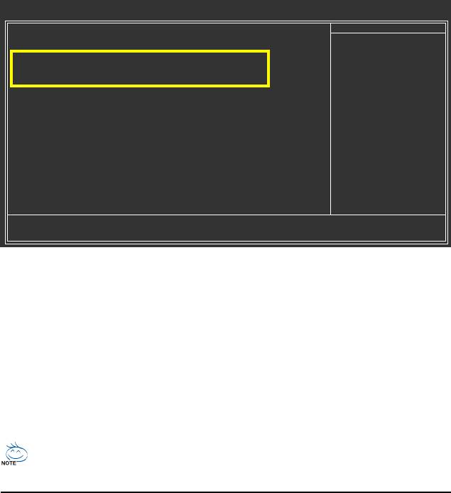
B. Enabling the SATA controllers and configuring hard drive mode in BIOS Setup
Make sure to enable the SATA controllers and configure hard drive mode in system BIOS Setup.
Step 1:
Turn on your computer and press <Delete> to enter BIOS Setup during the POST. In BIOS Setup, go to
Integrated Peripherals, ensure that Onboard SATA/IDE Device is enabled. (We recommend that
you leave Onboard SATA/IDE Ctrl Mode to the default IDE mode.)
CMOS Setup Utility-Copyright (C) 1984-2009 Award Software
Integrated Peripherals
OnChip IDE Channel [Enabled]
Item Help
OnChip SATA Type [Native IDE]
Menu Level
x OnChip SATA Port4/5 Type IDE
Onboard SATA/IDE Device [Enabled]
Onboard SATA/IDE Ctrl Mode [IDE]
Smart Backup [Press Enter]
Onboard Audio Function [Enabled]
Onboard LAN device [Press Enter]
Onboard 1394 Function [Enabled]
OnChip USB Controller [Enabled]
USB EHCI Controller [Enabled]
USB Keyboard Support [Disabled]
USB Mouse Support [Disabled]
Legacy USB storage detect [Enabled]
Onboard Serial Port 1 [3F8/IRQ4]
Onboard Parallel Port [378/IRQ7]
Parallel Port Mode [SPP]
x ECP Mode Use DMA 3
: Move Enter: Select +/-/PU/PD: Value F10: Save ESC: Exit F1: General Help
F5: Previous Values F6: Fail-Safe Defaults F7: Optimized Defaults
Figure 1
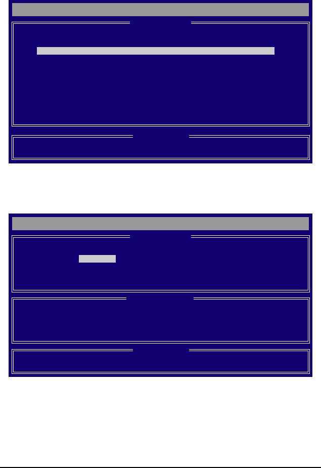
Step 2:
Press <Enter> on Smart Backup and go to the Controller 0 (GSATA2 0/1) or Controller 1 (GSATA2
2/3) submenu, depending on which ports you want to use (Controller 0 (GSATA2 0/1) controls the
GSATA2_0~1 ports and Controller 1 (GSATA2 2/3) controls the GSATA2_2~3 ports). Then enter the
Smart Backup Config submenu (Figure 2).
Step 3:
Select a RAID mode for your hard drives on the Smart Backup Config item (options include Perfor-
mance (RAID 0), Safe (RAID 1), Big (JBOD) and Normal (Port Multiplier) and use Apply RAID Config
for the settings to take effect.
The BIOS Setup menus described in this section may differ from the exact settings for your
motherboard. The actual BIOS Setup menu options you will see shall depend on the motherboard
you have and the BIOS version.
Appendix- 87 -

CMOS Setup Utility-Copyright (C) 1984-2009 Award Software
Smart Backup Config
Smart Backup Config [Performance (RAID 0)]
Item Help
Apply RAID Config [Press Enter]
Menu Level
=== Disk Info ===
[Port] [Model] [Capacity]
Port 0 WDCWD800JD-00JNA0 80GB
Port 1 WDCWD800JD-22LSA0 80GB
=== RAID Info ===
[Level] [Capacity] [Member]
Performance 0GB
: Move Enter: Select +/-/PU/PD: Value F10: Save ESC: Exit F1: General Help
F5: Previous Values F6: Fail-Safe Defaults F7: Optimized Defaults
Figure 2
Step 4:
After configuring the SATA ports, you are ready to proceed with the installation of the operating system.
You do not have to load the SATA controller driver during the installation process of the operating
system. Make sure to install the driver after the operating system is installed (using "Xpress Install" to
install all drivers required for your motherboard is recommended) for the SATA hard drives to work and
be detected properly.
Step 5:
Then install the Smart Backup utility from the Application Software menu on the driver Autorun screen
for monitoring the device/RAID status in the operating system (for more information, refer to section 5-
1-5, "Smart Backup Utility").
GA-MA790FXT-UD5P Motherboard - 88 -
5-1-3 Making a SATA RAID/AHCI Driver Diskette for Windows XP
(Required for AHCI and RAID Mode)
To successfully install operating system onto SATA hard drive(s) that is/are configured to RAID/AHCI
mode, you need to install the SATA controller driver during the OS installation. Without the driver, the
hard drive may not be recognized during the Windows setup process. First of all, copy the driver for
the SATA controller from the motherboard driver disk to a floppy disk. For installing Windows Vista,
please directly load the SATA RAID driver from the motherboard driver disk during the OS installation
process. For more details, refer to the next section. See the instructions below about how to copy the
(Note 1)
driver in MS-DOS mode
. Prepare a startup disk that has CD-ROM support and one blank formatted
floppy disk.
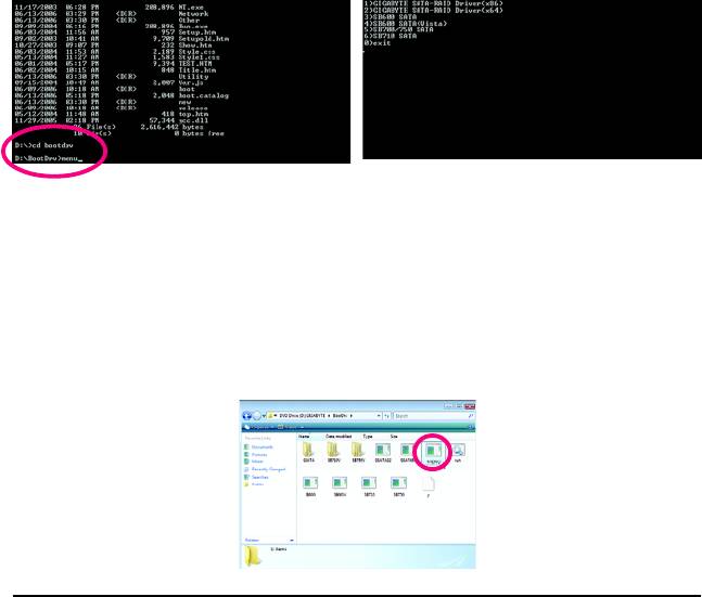
Step 1: Insert the prepared startup disk and motherboard driver disk in your system. Boot from the startup
disk. Once at the A:\> prompt, change to your optical drive (example: D:\>). At the D:\> prompt, type the
following two commands. Press <Enter> after each command (Figure 1):
cd bootdrv
menu
Step 2: When the controller menu (Figure 2) appears, remove the startup disk and insert the blank
formatted disk. Select the controller driver by pressing the corresponding letter from the menu. For
example, from the menu in Figure 2, to install Windows XP to your RAID/AHCI hard drives, select (5)
(Note 2)
SB700/750 SATA
. Your system will then automatically zip and transfer this driver file to the floppy
disk. Press <0> to exit when finished.
Figure 1 Figure 2
(Note 1) For users without a startup disk:
Use an alternative system and insert the motherboard driver disk. From your optical drive
folder, double click the MENU.exe file in the BootDrv folder (Figure 3). A command prompt
window will open similar to that in Figure 2.
(Note 2) The GIGABYTE SATA-RAID Driver in the menu in Figure 2 are required if you want to install
the Windows operating system onto hard drives that are connected to the GIGABYTE SATA2/
JMB322 controller and configured to AHCI mode in BIOS Setup. For installation of the driver
during the OS installation, refer to section 5-1-4.
Figure 3
Appendix- 89 -
5-1-4 Installing the SATA RAID/AHCI Driver and Operating System
With the SATA RAID/AHCI driver diskette and correct BIOS settings, you are ready to install Windows
Vista/XP onto your hard drive(s). The followings are examples of Windows XP and Vista installation on
the AMD SB750 SATA controller.
A. Installing Windows XP
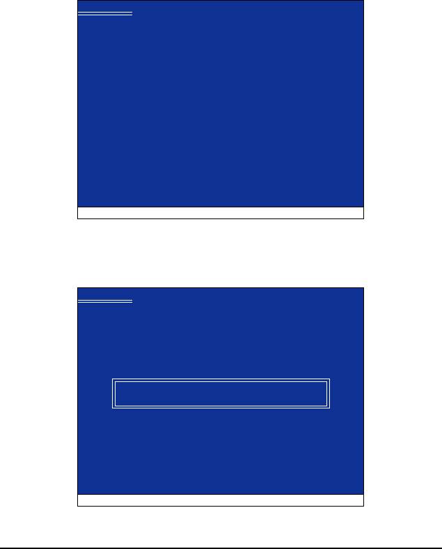
Step 1:
Restart your system to boot from the Windows XP setup disk and press <F6> as soon as you see the
message "Press F6 if you need to install a 3rd party SCSI or RAID driver" (Figure 1). A screen will then
appear asking you to specify additional device. Insert the floppy disk containing the SATA RAID/AHCI
driver and press <S>.
Windows Setup
Press F6 if you need to install a third party SCSI or RAID driver.
Figure 1
Step 2:
Then a controller menu similar to Figure 2 below will appear. Select AMD AHCI Compatible RAID
Controller-x86 platform and press <Enter>. On the next screen, press <Enter> to continue the driver
installation. After the driver installation, you can proceed with the Windows XP installation.
Windows Setup
You have chosen to configure a SCSI Adapter for use with Windows,
using a device support disk provided by an adapter manufacturer.
Select the SCSI Adapter you want from the following list, or press ESC
to return to the previous screen.
AMD AHCI Compatible RAID Controller-x86 platform
AMD AHCI Compatible RAID Controller-x64 platform
ENTER=Select F3=Exit
Figure 2
GA-MA790FXT-UD5P Motherboard - 90 -
B. Installing Windows Vista
(The procedure below assumes that only one RAID array exists in your system.)
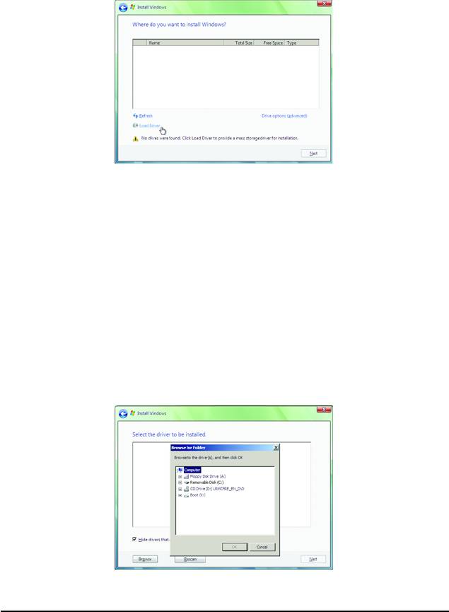
Step 1:
Restart your system to boot from the Windows Vista setup disk and perform standard OS installation
steps. When a screen similar to that below appears (RAID hard drive will not be detected at this stage),
select Load Driver (Figure 3).
Figure 3
Step 2:
Insert the motherboard driver disk (Method A) or the removable storage device such as USB flash drive
that contains the SATA RAID/AHCI driver (Method B), then specify the location of the driver (Figure 4).
Note: For users using a SATA optical drive, be sure to copy the driver files from the motherboard driver
disk to a USB flash drive before installing Windows Vista (go to the BootDrv folder and save the whole
SB750V foler to the USB flash drive). Then use Method B to load the driver.
Method A:
Insert the motherboard driver disk into your system and browse to the following directory:
\BootDrv\SB750V\LH
For Windows Vista 64-bit, browse to the LH64A folder.
Method B:
Insert the USB flash drive containing the driver files and browse to the LH (for Windows Vista 32-bit) or
LH64A (for Windows Vista 64-bit) folder.
Figure 4
Appendix- 91 -
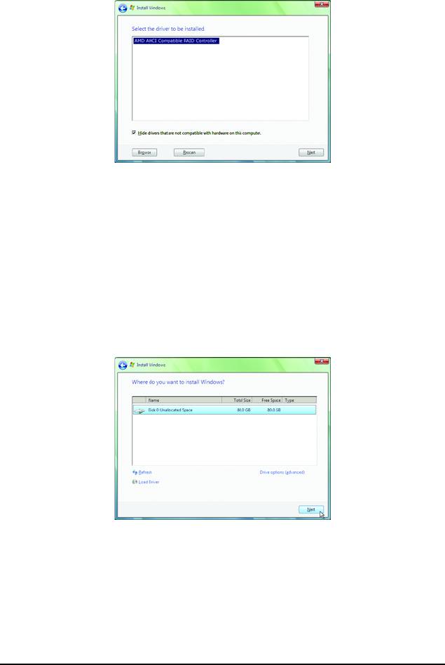
Step 3:
When a screen as shown in Figure 5 appears, select AMD AHCI Compatible RAID Controller and
press Next.
Figure 5
Step 4:
After the driver is loaded, the RAID drive will appear. Select the RAID drive and then press Next to
continue the OS installation (Figure 6).
Figure 6
GA-MA790FXT-UD5P Motherboard - 92 -
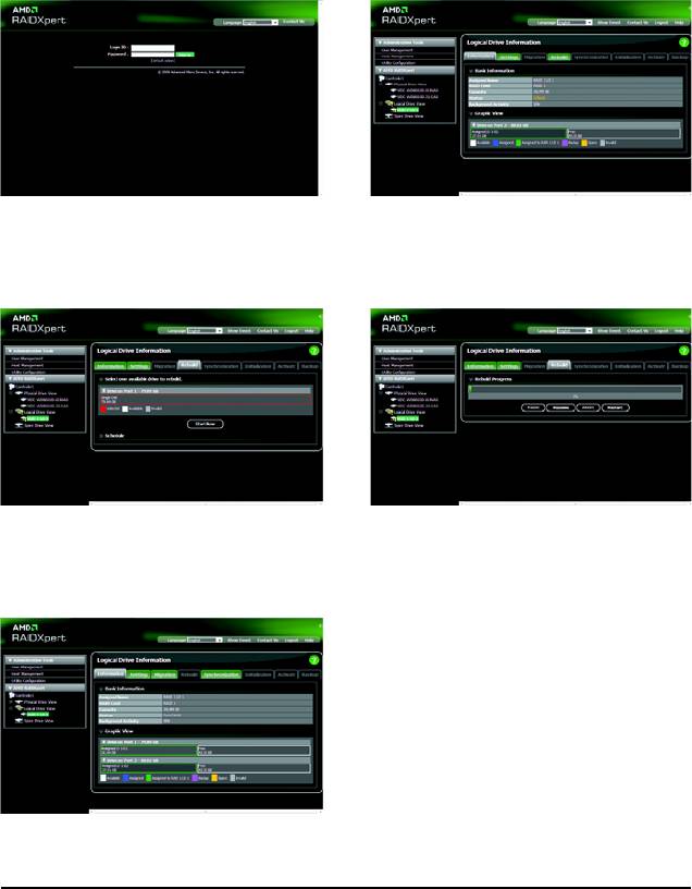
Rebuilding an Array:
Rebuilding is the process of restoring data to a hard drive from other drives in the array. Rebuilding
applies only to fault-tolerant arrays such as RAID 1, RAID 5, or RAID 10 arrays. To replace the old
drive, make sure to use a new drive of equal or greater capacity. The procedures below assume a
new drive is added to replace a failed drive to rebuild a RAID 1 array.
While in the operating system, make sure the
chipset drivers
and ATi SB700/750 RAID Utility have
been installed from the motherboard driver disk. Then launch the AMD RAIDXpert from All Programs
in the Start Menu.
Step 1:
Step 2:
Enter the login ID and password (default:"admin"),
Select the RAID array to be rebuilt under Logical
and then click Sign in to launch AMD RAIDXpert.
Drive View and click the Rebuild tab in the
Logical Drive Information pane.
Step 3:
Step 4:
Select one available drive and click Start Now
The rebuilding progress is displayed on the
to start the rebuilding process.
screen and you can select Pause/Resume/
Abort/Restart during the rebuilding process.
Step 5:
When done, the array's status on the Information page
in the Logical Drive Information pane will display as
Functional.
Appendix- 93 -
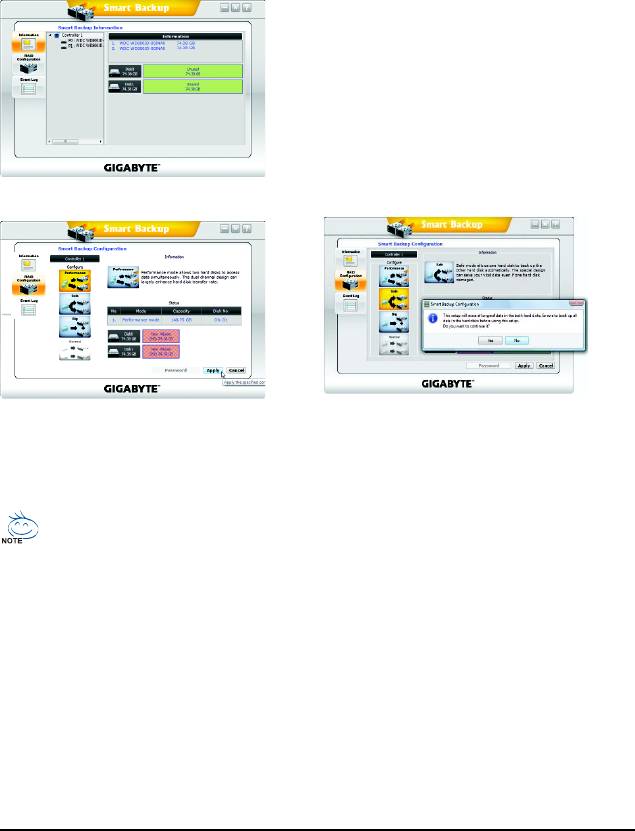
5-1-5 Smart Backup Utility
The Smart Backup utility is an easy-to-use tool that allows you to set up a RAID array on the GIGABYTE
SATA2/JMB322 SATA controller and to monitor the RAID status and view the hard drive information in
the operating system.
A. Installing Smart Backup:
Insert the motherboard driver disk. When the Autorun screen appears, go to Application Software and
select Smart Backup for installation.
B. The Smart Backup Interface:
. Information
Provides information on the connected hard
drives, such as model, capacity and status.
. RAID Configuration
Allows you to set the operating mode for your hard
drives. Options include Performance (RAID 0), Safe
(RAID 1), Big (JBOD), and Normal (Port Multiplier).
. Event Log
Provides the event log list.
C. Configuring a RAID Array:
Step 1:
Step 2:
Go to the RAID Configuration screen. Select
When the confirmation message appears, click
a RAID mode (e.g. Performance) and click
Yes to confirm and begin the RAID creation
Apply.
process. Click OK when completed.
Safe mode also allows you to back up a hard drive that already contains data (the source
drive) to another one (the backup drive). Before doing this, you have to note the following:
A. The backup drive's size must be larger or equal to the source drive's size.
B. The source drive must be connected to the GSATA2_0/GSATA2_2 connector and the
backup drive to the GSATA2_1/GSATA2_3 connector. The backup drive's original data
will be erased when you enable Safe mode.
C. Both source drive and backup drive need to support LOG sector. (If a hard drive that does not
support LOG is used, the Information area will display as "Not support Backup.")
D. You can also use the Smart Backup submenu in BIOS Setup to select Safe mode to back
up your hard drive. The Backup will be automatically performed once you enter the
operating system. Launch the Smart Backup utility to check the backup progress.
(Note) To rebuild a RAID 1 array, replace the failed drive with a new one. While in the operating system,
the rebuild will be performed automatically. You can launch the Smart Backup utility to check the
rebuild progress. Click OK to complete when prompted.
GA-MA790FXT-UD5P Motherboard - 94 -
5-2 Configuring Audio Input and Output
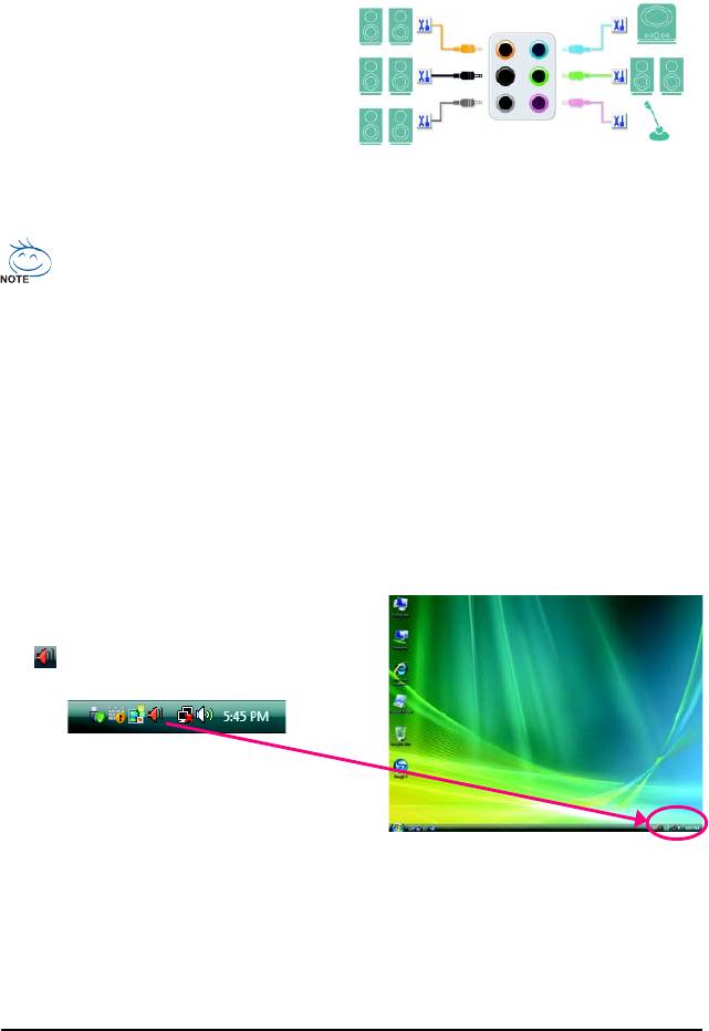
5-2-1 Configuring 2/4/5.1/7.1-Channel Audio
The motherboard provides six audio jacks on the
back panel which support 2/4/5.1/7.1-channel audio.
Center/Subwoofer
The picture to the right shows the default audio
Line In
Speaker Out
jack assignments. The integrated HD (High Definition)
Rear Speaker Out
Front Speaker Out
audio provides jack retasking capability that
Mic In
allows the user to change the function for each
Side Speaker Out
jack through the audio driver. For example, in a
4-channel audio configuration, if a Rear speaker is plugged into the default Center/Subwoofer speaker
out jack, you can retask the Center/Subwoofer speaker out jack to be Rear speaker out.
• To install a microphone, connect your microphone to the Mic in jack and manually configure
the jack for microphone functionality.
• Audio signals will be present on both of the front and back panel audio connections simultaneously.
If you want to mute the back panel audio (only supported when using an HD front panel audio
module), refer to instructions on the next page.
High Definition Audio (HD Audio)
HD Audio includes multiple high quality digital-to-analog converters (DACs) that support 44.1KHz/
48KHz/ 96KHz/192KHz sampling rate. HD Audio features multistreaming capabilities that allow multiple
audio streams (in and out) to be simultaneously processed. For example, users can listen to MP3
music, have an Internet chat, make a telephone call over the Internet, and etc. all at the same time.
A. Configuring Speakers:
(The following instructions use Windows Vista as the example operating system.)
Step 1:
After installing the audio driver, the HD Audio Manager
icon will appear in the notification area. Double-
click the icon to access the HD Audio Manager.
(Note) 2/4/5.1/7.1-Channel Audio Configurations:
Refer to the following for multi-channel speaker configurations.
• 2-channel audio: Headphone or Line out.
• 4-channel audio: Front speaker out and Rear speaker out.
• 5.1-channel audio: Front speaker out, Rear speaker out, and Center/Subwoofer speaker out.
• 7.1-channel audio: Front speaker out, Rear speaker out, Center/Subwoofer speaker out, and Side speaker out.
Appendix- 95 -
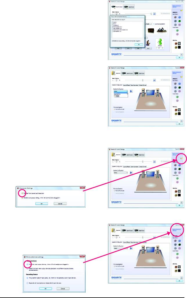
Step 2:
Connect an audio device to an audio jack. The The
current connected device is dialog box appears.
Select the device according to the type of device you
connect. Then click OK.
Step 3:
On the Speakers screen, click the Speaker Configu-
ration tab. In the Speaker Configuration list, select
Stereo, Quadraphonic, 5.1 Speaker, or 7.1 Speaker
according to the type of speaker configuration you wish
to set up. Then the speaker setup is completed.
B. Configuring Sound Effect:
You may configure an audio environment on the Sound Effects tab.
C. Activating an AC'97 Front Panel Audio Module:
If your chassis provides an AC'97 front panel audio
module, to activate the AC'97 functionality, click the
tool icon on the Speaker Configuration tab. On the
Connector Settings dialog box, select the Disable
front panel jack detection check box. Click OK to
complete.
D. Muting the Back Panel Audio (For HD Audio Only):
Click Device advanced settings on the top right cor-
ner on the Speaker Configuration tab to open the
Device advanced settings dialog box. Select the Mute
the rear output device, when a front headphone
plugged in check box. Click OK to complete.
GA-MA790FXT-UD5P Motherboard - 96 -
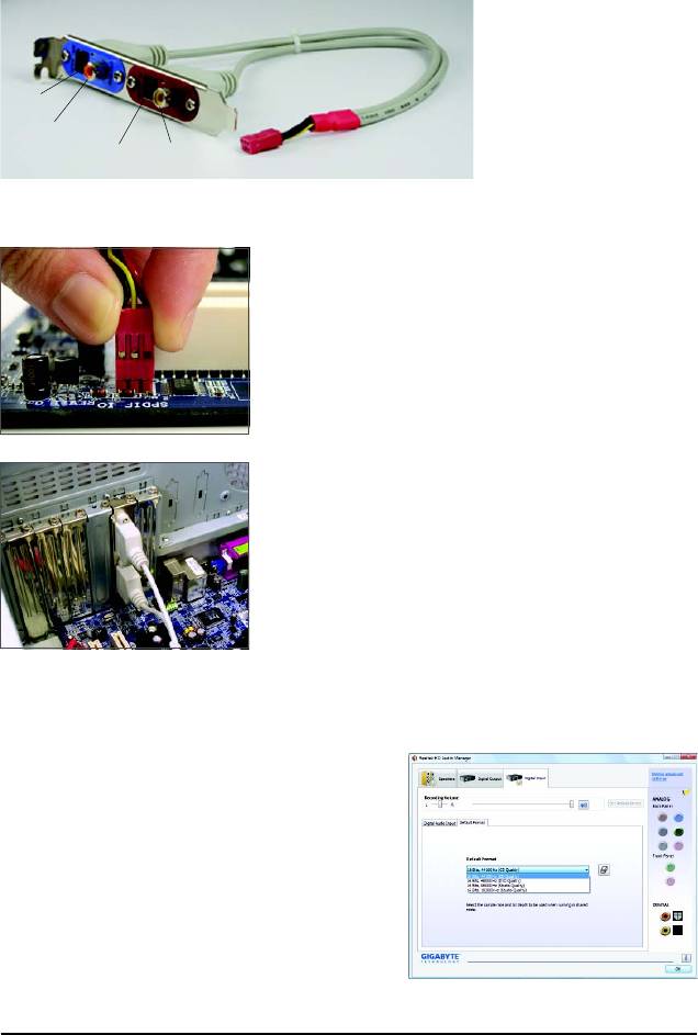
5-2-2 Configuring S/PDIF In/Out
The S/PDIF in and out cable (optional) provides S/PDIF in and S/PDIF out functionalities.
Optical
S/PDIF Out
Coaxial
S/PDIFOut
Optical
Coaxial
S/PDIF In
S/PDIFIn
A. Installing the S/PDIF In and Out Cable:
Step 1:
First, attach the connector at the end of the cable to the SPDIF_IO
header on your motherboard.
Step 2:
Secure the metal bracket to the chassis back panel with a
screw.
B. Configuring S/PDIF in:
The S/PDIF in jacks on the SPDI/F In and Out cable allow you to input digital audio signals to the
computer for audio processing.
Step:
After connecting the S/PDIF in device, access the Digital
Input screen. Click the Default Format tab to select the
default format. Click OK to complete.
(Note) The actual locations of the SPDIF In and SPDIF Out connectors may differ by model.
Appendix- 97 -
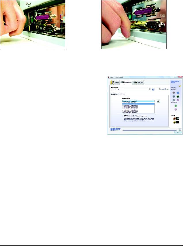
C. Configuring S/PDIF Out:
The S/PDIF out jacks can transmit audio signals to an external decoder for decoding to get the best
audio quality. To output S/PDIF digital audio signals to an external decoder, connect a S/PDIF coaxial
cable or a S/PDIF optical cable (either one) to the optical/coxial S/PDIF out connector on the motherboard
back panel (or on the optional S/PDIF in and out cable).
C-1. Conneting a S/PDIF Out Cable
S/PDIF Coaxial Cable S/PDIF Optical Cable
C-2. Configuring S/PDIF Out:
Step:
On the Digital Output screen, click the Default For-
mat tab and then select the sample rate and bit depth.
Click OK to complete.
GA-MA790FXT-UD5P Motherboard - 98 -
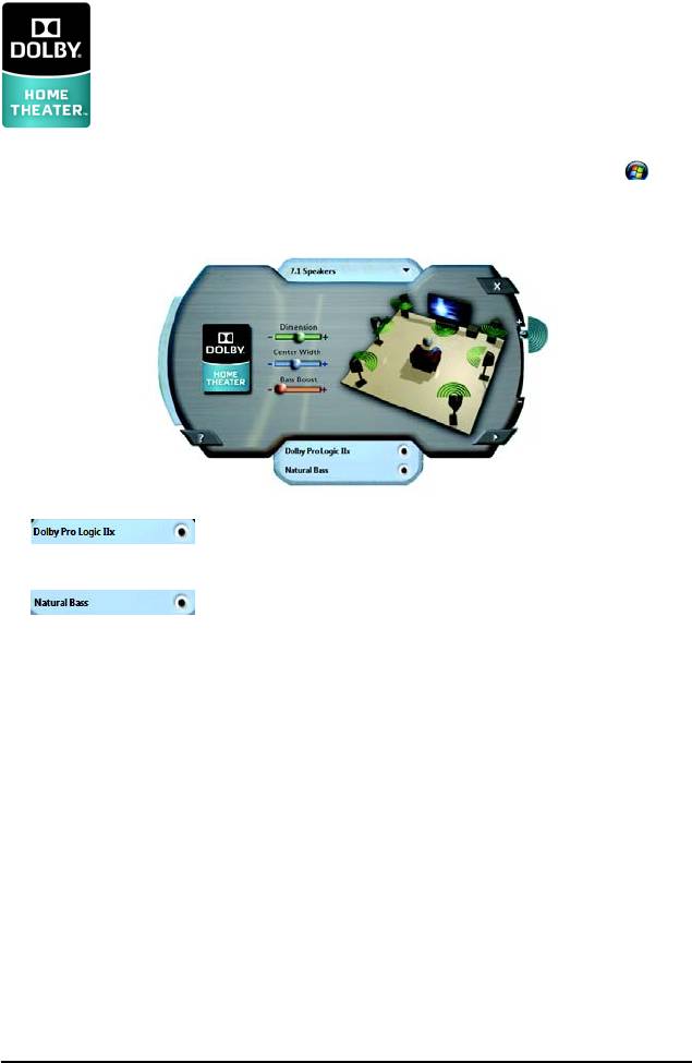
5-2-3 Enabling the Dolby Home Theater Function
Before Dolby Home Theater is enabled, you get only 2-channel playback output (from
the front speakers) when playing 2-channel stereo sources. You must play 4-, 5.1-, or
7.1- channel content to get 4-, 5.1-, or 7.1- channel audio effects. With Dolby Home
Theater enabled, 2-channel stereo content will be transformed into multi-channel audio,
(Note)
creating a virtual surround sound environment
.
Install the Dolby GUI Software driver from the motherboard driver disk. Click the Start icon . Point
to All Programs, Dolby Control Center to access the utility.
(The following illustration demonstrates a 7.1-speaker configuration as an example.)
1. : Click Dolby Pro Logic IIx. The system will expand 2-channel audio
for a 7.1-channel surround sound playback.
2. : Click Natural Bass to enable speaker bass effect.
(Note) When Dolby Digital Live is enabled, only digital audio output (S/PDIF) is working, and you will
not hear any sound from analog speakers or headphone.
Appendix- 99 -
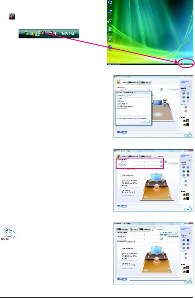
5-2-4 Configuring Microphone Recording
Step 1:
After installing the audio driver, the HD Audio Manager
icon will appear in the notification area. Double-
click the icon to access the HD Audio Manager.
Step 2:
Connect your microphone to the Mic in jack (pink)
on the back panel or the Mic in jack (pink) on the front
panel. Then configure the jack for microphone
functionality.
Note: The microphone functions on the front panel
and back panel cannot be used at the same time.
Step 3:
Go to the Microphone screen. Do not mute the
recording volume, or you'll not be able to record the
sound. To hear the sound being recorded during the
recording process, do not mute the playback volume.
It is recommended that you set the volumes at a
middle level.
If you want to change the current sound input
default device to microphone, right-click on
Microphone and select Set Default Device.
GA-MA790FXT-UD5P Motherboard - 100 -
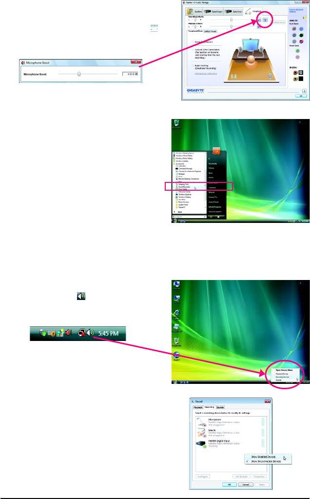
Step 4:
To raise the recording and playback volume for the
microphone, click the Microphone Boost icon
on the right of the Recording Volume slider and set
the Microphone Boost level.
Step 5:
After completing the settings above, click Start, point
to All Programs, point to Accessories, and then
click Sound Recorder to begin the sound recording.
* Enabling Stereo Mix
If the HD Audio Manager does not display the recording device you wish to use, refer to the steps
below. The following steps explain how to enable Stereo Mix (which may be needed when you want
to record sound from your computer).
Step 1:
Locate the Volume icon in the notification area
and right-click on this icon. Select Recording
Devices.
Step 2:
On the Recording tab, right-click on an empty space
and select Show Disabled Devices.
Appendix- 101 -
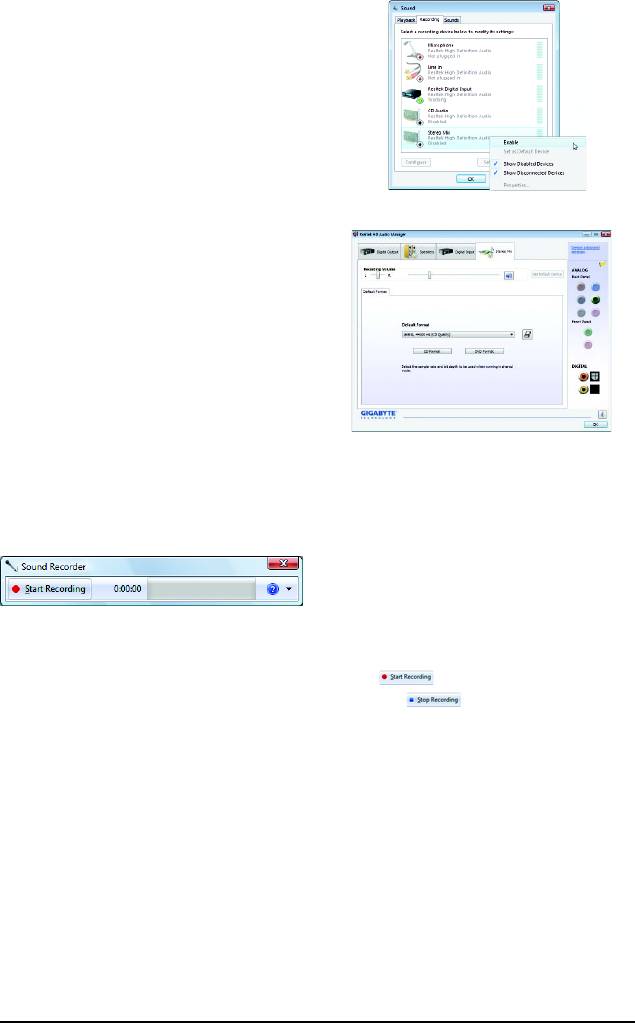
Step 3:
When the Stereo Mix item appears, right-click on
this item and select Enable. Then set it as the default
device.
Step 4:
Now you can access the HD Audio Manager to
configure Stereo Mix and use Sound Recorder to
record the sound.
5-2-5 Using the Sound Recorder
A. Recording Sound:
1. Make sure you have connected the sound input device (e.g. microphone) to the computer.
2. To record the audio, click the Start Recording button .
3. To stop recording audio, click the Stop Recording button .
Be sure to save the recorded audio file upon completion.
B. Playing the Recorded Sound:
You can play your recording in a digital media player program that supports your audio file format.
GA-MA790FXT-UD5P Motherboard - 102 -

5-3 Troubleshooting
5-3-1 Frequently Asked Questions
To read more FAQs for your motherboard, please go to the Support\Motherboard\FAQ page on
GIGABYTE's website.
Q:In the BIOS Setup program, why are some BIOS options missing?
A:Some advanced options are hidden in the BIOS Setup program. Press <Delete> to enter BIOS Setup
during the POST. In the Main Menu, press <Ctrl>+<F1> to show the advanced options.
Q:Why is the light of my keyboard/optical mouse still on after the computer shuts down?
A:Some motherboard provides a small amount of standby power after the computer shuts down and
that's why the light is still on.
Q:How do I clear the CMOS values?
A:If your motherboard has a clearing CMOS jumper, refer to the instructions on the CLR_CMOS jumper
in Chapter 1 to short the jumper to clear the CMOS values. If your board doesn't have this jumper,
refer to the instructions on the motherboard battery in Chapter 1. You can temporarily remove the
battery from the battery holder to stop supplying power to the CMOS, which will clear the CMOS
values after about one minute. Refer to the steps below:
Steps:
1. Turn off your computer and unplug the power cord.
2. Gently remove the battery from the battery holder and wait for one minute.
(Or use a metal object like a screwdriver to touch the positive and negative terminals of the battery
holder, making them short for 5 seconds.)
3. Replace the battery.
4. Plug in the power cord and restart your computer.
5. Press <Delete> to enter BIOS Setup. Select "Load Fail-Safe Defaults" (or "Load Optimized Defaults")
to load BIOS default settings.
6. Saves changes and exit BIOS Setup (select "Save & Exit Setup") to restart your computer.
Q:Why do I still get a weak sound even though I have turned my speaker to the maximum volume?
A:Make sure your speaker is equipped with an internal amplifier. If not, try a speaker with power/
amplifier.
Q:What do the beeps emitted during the POST mean?
A:The following Award BIOS beep code descriptions may help you identify possible computer problems.
(For reference only.)
1 short: System boots successfully
2 short: CMOS setting error
1 long, 1 short: Memory or motherboard error
1 long, 2 short: Monitor or graphics card error
1 long, 3 short: Keyboard error
1 long, 9 short: BIOS ROM error
Continuous long beeps: Graphics card not inserted properly
Continuous short beeps: Power error
Appendix- 103 -
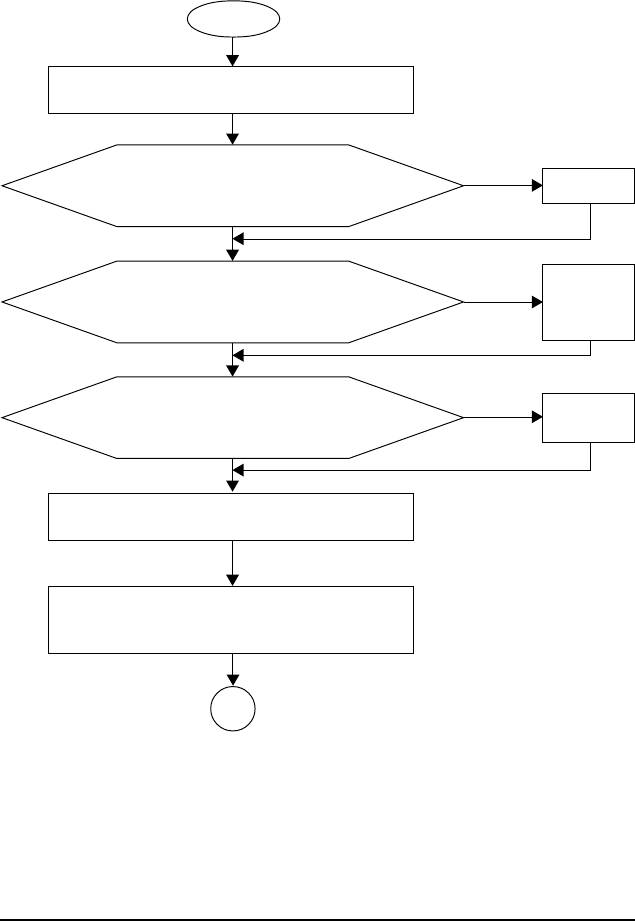
5-3-2 Troubleshooting Procedure
If you encounter any troubles during system startup, follow the troubleshooting procedure below to
solve the problem.
START
Turn off the power. Remove all peripherals, connecting cables, and
power cord etc.
Make sure the motherboard does not short-circuit with the chassis
Ye s
Isolate the short
circuit.
or other metal objects.
No
The problem is verified and solved.
Secure the CPU
Check if the CPU cooler is attached to the CPU securely. Is the
cooler on the CPU.
No
power connector of the CPU cooler connected to the CPU_FAN
Connect the CPU
cooler power cable
header properly?
to the motherboard.
Ye s
The problem is verified and solved.
Correctly insert the
No
Check if the memory is installed properly on the memory slot.
memory into the
memory socket.
Ye s
The problem is verified and solved.
Insert the graphics card. Connect the ATX main power cable and the 12V
power cable. Turn on the power to start the computer.
Press <Delete> to enter BIOS Setup. Select "Load Fail-Safe Defaults"
(or "Load Optimized Defaults"). Select "Save & Exit Setup" to save
changes and exit BIOS Setup.
A
(Continued...)
GA-MA790FXT-UD5P Motherboard - 104 -
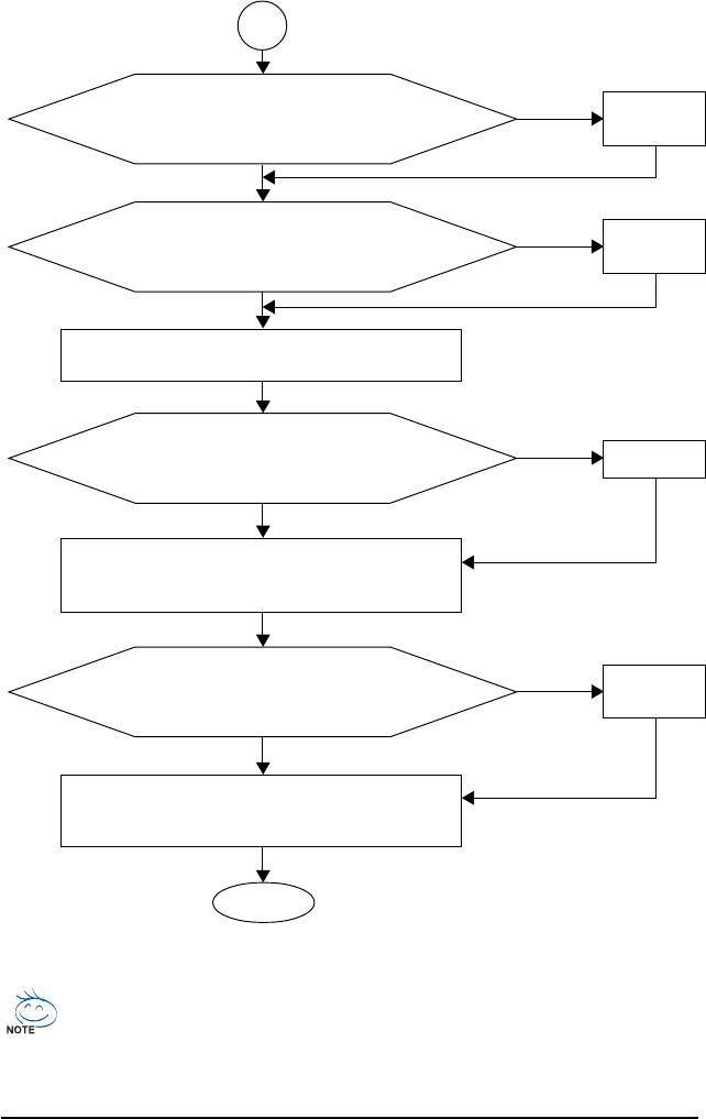
A
The power supply,
When the computer is turned on, is the CPU cooler running?
No
CPU or CPU socket
might fail.
Ye s
The problem is verified and solved.
The graphics card,
No
Check if there is display on your monitor.
expansion slot, or
monitor might fail.
Ye s
The problem is verified and solved.
Turn off the computer. Plugg in the keyboard and mouse and restart the
computer.
No
The keyboard or
Check if the keyboard is working properly.
mouse might fail.
Ye s
Press <Delete> to enter BIOS Setup. Select "Load Fail-Safe Defaults"
(or "Load Optimized Defaults"). Select "Save & Exit Setup" to save
The problem is verified and solved.
changes and exit BIOS Setup.
The IDE/SATA
Turn off the computer and connect the IDE/SATA devices.
No
device, connector,
Check if the system can boot successfully.
or cable might fail.
Ye s
Reinstall the operating system. Reinstall other devices one by one (install
one device at one time and then boot the system to see if the device
The problem is verified and solved.
works successfully).
END
If the procedure above is unable to solve your problem, contact the place of purchase or local
dealer for help. Or go to the Support\Technical Service Zone page to submit your question. Our
customer service staff will reply you as soon as possible.
Appendix- 105 -
5-4 Regulatory Statements
Regulatory Notices
This document must not be copied without our written permission, and the contents there of must not be
imparted to a third party nor be used for any unauthorized purpose. Contravention will be prosecuted.
We believe that the information contained herein was accurate in all respects at the time of printing.
GIGABYTE cannot, however, assume any responsibility for errors or omissions in this text. Also note
that the information in this document is subject to change without notice and should not be construed as
a commitment by GIGABYTE.
Our Commitment to Preserving the Environment
In addition to high-efficiency performance, all GIGABYTE motherboards fulfill European Union regula-
tions for RoHS (Restriction of Certain Hazardous Substances in Electrical and Electronic Equipment)
and WEEE (Waste Electrical and Electronic Equipment) environmental directives, as well as most
major worldwide safety requirements. To prevent releases of harmful substances into the environment
and to maximize the use of our natural resources, GIGABYTE provides the following information on
how you can responsibly recycle or reuse most of the materials in your "end of life" product.
Restriction of Hazardous Substances (RoHS) Directive Statement
GIGABYTE products have not intended to add and safe from hazardous substances (Cd, Pb, Hg, Cr+6,
PBDE and PBB). The parts and components have been carefully selected to meet RoHS requirement.
Moreover, we at GIGABYTE are continuing our efforts to develop products that do not use internationally
banned toxic chemicals.
Waste Electrical & Electronic Equipment (WEEE) Directive Statement
GIGABYTE will fulfill the national laws as interpreted from the 2002/96/EC WEEE (Waste Electrical and
Electronic Equipment) directive. The WEEE Directive specifies the treatment, collection, recycling and
disposal of electric and electronic devices and their components. Under the Directive, used equipment
must be marked, collected separately, and disposed of properly.
WEEE Symbol Statement
The symbol shown below is on the product or on its packaging, which indicates that this
product must not be disposed of with other waste. Instead, the device should be taken to
the waste collection centers for activation of the treatment, collection, recycling and
disposal procedure. The separate collection and recycling of your waste equipment at the
time of disposal will help to conserve natural resources and ensure that it is recycled in a manner that
protects human health and the environment. For more information about where you can drop off your
waste equipment for recycling, please contact your local government office, your household waste
disposal service or where you purchased the product for details of environmentally safe recycling.
When your electrical or electronic equipment is no longer useful to you, "take it back" to your local
or regional waste collection administration for recycling.
If you need further assistance in recycling, reusing in your "end of life" product, you may contact us
at the Customer Care number listed in your product's user's manual and we will be glad to help you
with your effort.
GA-MA790FXT-UD5P Motherboard - 106 -
Finally, we suggest that you practice other environmentally friendly actions by understanding and
using the energy-saving features of this product (where applicable), recycling the inner and outer
packaging (including shipping containers) this product was delivered in, and by disposing of or
recycling used batteries properly. With your help, we can reduce the amount of natural resources
needed to produce electrical and electronic equipment, minimize the use of landfills for the disposal of
"end of life" products, and generally improve our quality of life by ensuring that potentially hazardous
substances are not released into the environment and are disposed of properly.
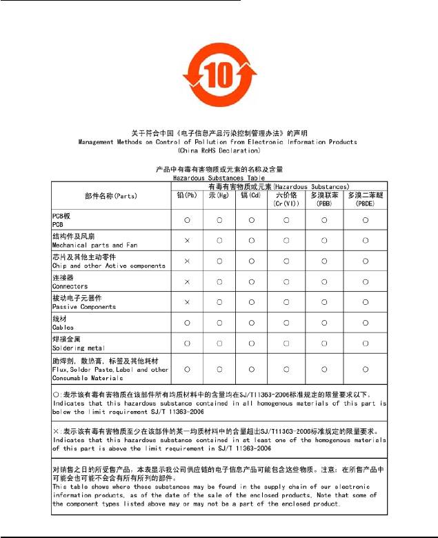
China Restriction of Hazardous Substances Table
The following table is supplied in compliance with China's Restriction of Hazardous Substances (China
RoHS) requirements:
Appendix- 107 -

GA-MA790FXT-UD5P Motherboard - 108 -

Appendix- 109 -

GA-MA790FXT-UD5P Motherboard - 110 -
Contact Us
GIGA-BYTE TECHNOLOGY CO., LTD.
NINGBO G.B.T. TECH. TRADING CO., LTD. - China
Address: No.6, Bau Chiang Road, Hsin-Tien,
WEB address : http://www.gigabyte.cn
Taipei 231, Taiwan
Shanghai
TEL: +886-2-8912-4000
TEL: +86-21-63410999
FAX: +886-2-8912-4003
FAX: +86-21-63410100
Tech. and Non-Tech. Support (Sales/Marketing) :
Beijing
http://ggts.gigabyte.com.tw
TEL: +86-10-62102838
WEB address (English): http://www.gigabyte.com.tw
FAX: +86-10-62102848
WEB address (Chinese): http://www.gigabyte.tw
Wuhan
G.B.T. INC. - U.S.A.
TEL: +86-27-87851312
TEL: +1-626-854-9338
FAX: +86-27-87851330
FAX: +1-626-854-9339
GuangZhou
Tech. Support:
TEL: +86-20-87540700
http://rma.gigabyte-usa.com
FAX: +86-20-87544306
Web address: http://www.gigabyte.us
Chengdu
G.B.T. INC (USA) - Mexico
TEL: +86-28-85236930
Tel: +1-626-854-9338 x 215 (Soporte de habla hispano)
FAX: +86-28-85256822
FAX: +1-626-854-9339
Xian
Correo: soporte@gigabyte-usa.com
TEL: +86-29-85531943
Tech. Support:
FAX: +86-29-85510930
http://rma.gigabyte-usa.com
Shenyang
Web address: http://latam.giga-byte.com/
TEL: +86-24-83992901
GIGA-BYTE SINGAPORE PTE. LTD. - Singapore
FAX: +86-24-83992909
WEB address : http://www.gigabyte.sg
GIGABYTE TECHNOLOGY (INDIA) LIMITED - India
Thailand
WEB address : http://www.gigabyte.in
WEB address : http://th.giga-byte.com
Saudi Arabia
Vietnam
WEB address : http://www.gigabyte.com.sa
WEB address : http://www.gigabyte.vn
GIGABYTE TECHNOLOGY PTY. LTD. - Australia
WEB address : http://www.gigabyte.com.au
Appendix- 111 -
G.B.T. TECHNOLOGY TRADING GMBH - Germany
Hungary
WEB address : http://www.gigabyte.de
WEB address : http://www.giga-byte.hu
G.B.T. TECH. CO., LTD. - U.K.
Turkey
WEB address : http://www.giga-byte.co.uk
WEB address : http://www.gigabyte.com.tr
GIGA-BYTE TECHNOLOGY B.V. - The Netherlands
Russia
WEB address : http://www.giga-byte.nl
WEB address : http://www.gigabyte.ru
GIGABYTE TECHNOLOGY FRANCE - France
Poland
WEB address : http://www.gigabyte.fr
WEB address : http://www.gigabyte.pl
Sweden
Ukraine
WEB address : http://www.giga-byte.se
WEB address : http://www.gigabyte.ua
Italy
Romania
WEB address : http://www.giga-byte.it
WEB address : http://www.gigabyte.com.ro
Spain
Serbia
WEB address : http://www.giga-byte.es
WEB address : http://www.gigabyte.co.yu
Greece
Kazakhstan
WEB address : http://www.giga-byte.gr
WEB address : http://www.giga-byte.kz
Czech Republic
You may go to the GIGABYTE website, select your language
WEB address : http://www.gigabyte.cz
in the language list on the top right corner of the website.
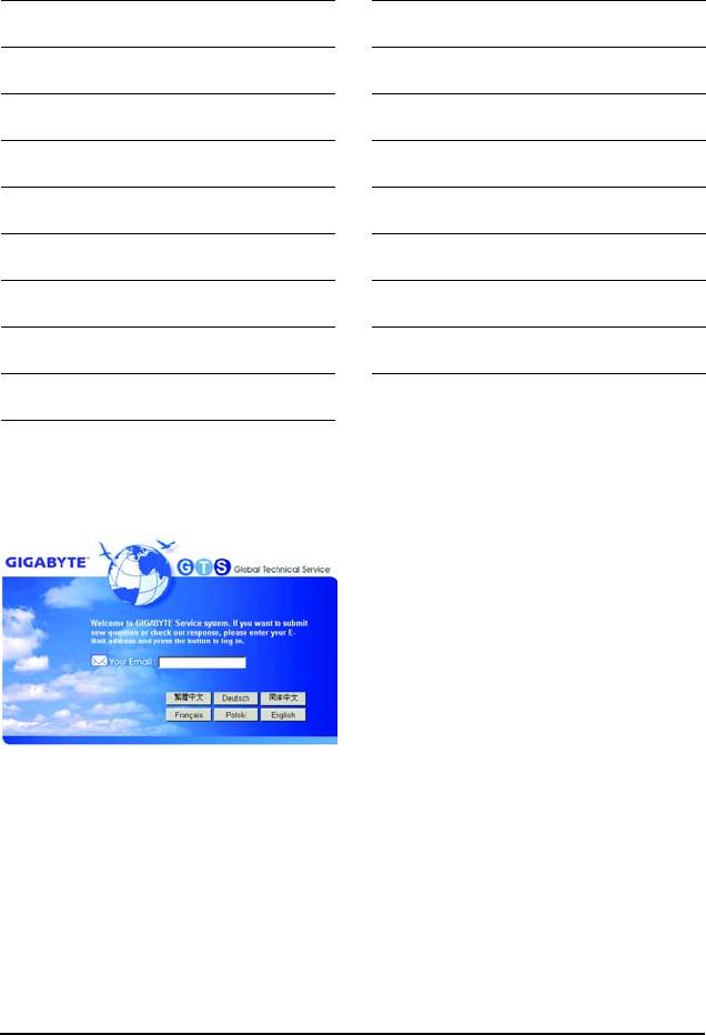
GIGABYTE Global Service System
To submit a technical or non-technical (Sales/
Marketing) question, please link to :
http://ggts.gigabyte.com.tw
Then select your language to enter the system.
GA-MA790FXT-UD5P Motherboard - 112 -


