ASRock X79 Extreme11: 2. Installation
2. Installation: ASRock X79 Extreme11
2. Installation
This is a CEB form factor (12.0" x 10.5", 30.5 x 26.7 cm) motherboard. Before you
install the motherboard, study the conguration of your chassis to ensure that the
motherboard ts into it.
Make sure to unplug the power cord before installing or removing the
motherboard. Failure to do so may cause physical injuries to you and
damages to motherboard components.
2.1 Screw Holes
Place screws into the holes indicated by circles to secure the motherboard to the
chassis.
Do not over-tighten the screws! Doing so may damage the motherboard.
2.2 Pre-installation Precautions
Take note of the following precautions before you install motherboard components
or change any motherboard settings.
1. Unplug the power cord from the wall socket before touching any
components.
2. To avoid damaging the motherboard’s components due to static
electricity, NEVER place your motherboard directly on the carpet
or the like. Also remember to use a grounded wrist strap or touch a
safety grounded object before you handle the components.
3. Hold components by the edges and do not touch the ICs.
4. Whenever you uninstall any component, place it on a grounded anti-
static pad or in the bag that comes with the component.
5. When placing screws into the screw holes to secure the mother-
board to the chassis, please do not over-tighten the screws! Doing
so may damage the motherboard.
English
Before you install or remove any component, ensure that the power is switched
off or the power cord is detached from the power supply. Failure to do so may
cause severe damage to the motherboard, peripherals, and/or components.
12
X79 Extreme11 Motherboard
2.3 CPU Installation
For the installation of Intel 2011-Pin CPU,
please follow the steps below.
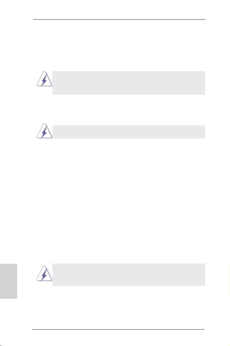
2011-Pin Socket Overview
Before you insert the 2011-Pin CPU into the socket, please check if the
CPU surface is unclean or if there are any bent pins in the socket. Do
not force to insert the CPU into the socket if above situation is found.
Otherwise, the CPU will be seriously damaged.
Step 1. Open the socket:
Step 1-1. Disengage the left lever by pressing it
down and sliding it out of the hook.
Step 1-2. Disengage the right lever by pressing
it down and sliding it out of the hook.
Step 1-3. Keep the right lever positioned at
about 90 degrees in order to ip up
the load plate.
Pin1
Step 2. Insert the 2011-Pin CPU:
Step 2-1. Hold the CPU by the edge with the
triangle mark(Pin 1) on your upper
right corner.
English
13
X79 Extreme11 Motherboard
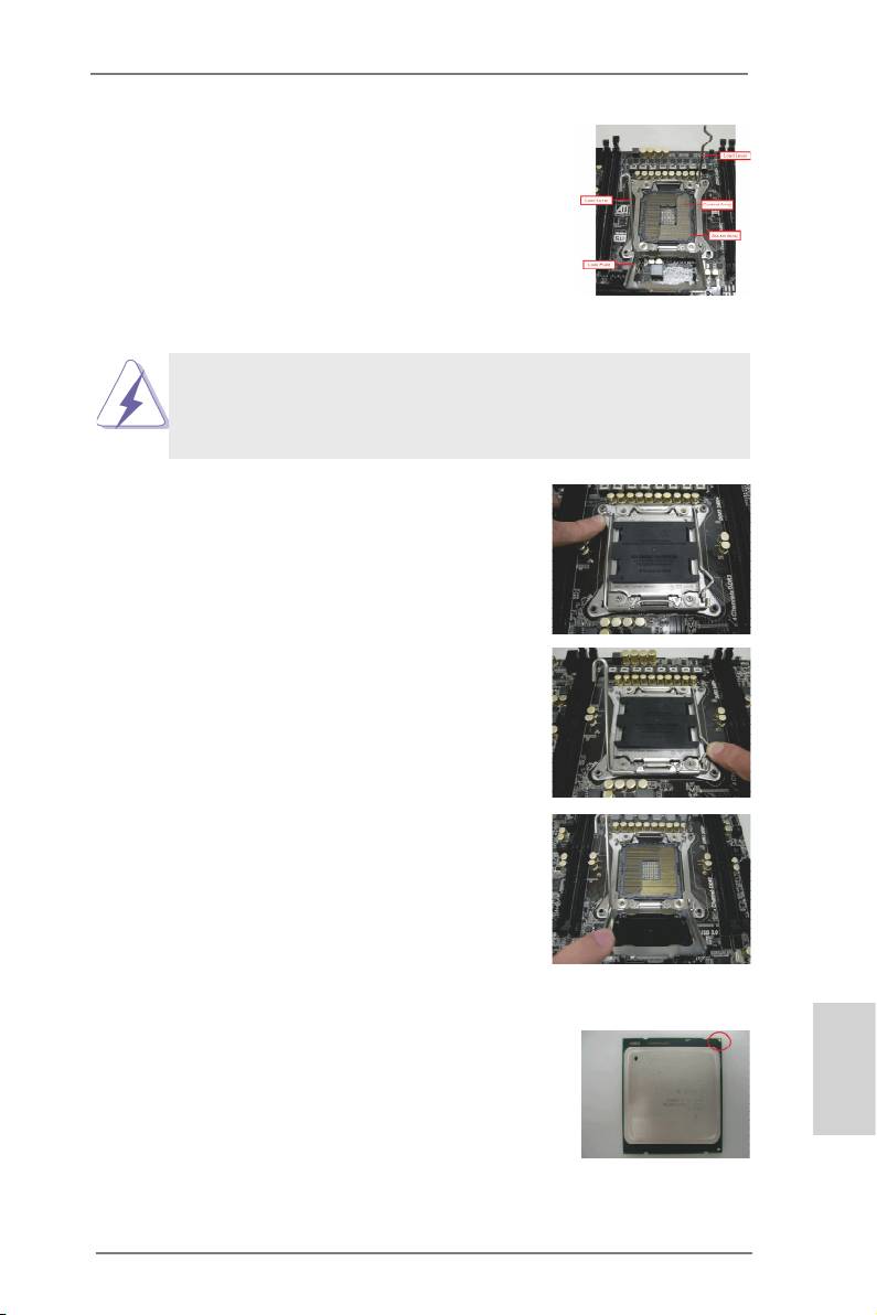
Step 2-2. Locate Pin1 and the two orientation
key notches.
orientation key notch
alignment key
Pin1
orientation key notch
alignment key
2011-Pin CPU
2011-Pin Socket
For proper inserting, please ensure to match the four orientation key
notches of the CPU with the four alignment keys of the socket.
Step 2-3. Carefully place the CPU into the
socket by using a purely vertical mo-
tion.
Step 2-4. Verify that the CPU is within the sock-
et and properly mated to the orient
keys.
Step 3. Close the socket:
Step 3-1. Flip the load plate onto the IHS, then
the cover will automatically come off
by itself.
The cover must be placed if returning the
motherboard for after service.
Step 3-2. Press down the right load lever, and
secure it with the load plate tab under
English
the retention tab.
Step 3-3. Press down the left load lever, and
secure it with the load plate tab under
the retention tab.
14
X79 Extreme11 Motherboard
2.4 Installation of CPU Fan and Heatsink
This motherboard is equipped with a 2011-Pin socket that supports Intel 2011-
Pin CPUs. Please adopt the type of heatsink and cooling fan compliant with Intel
2011-Pin CPU to dissipate heat. Before you install the heatsink, you need to spray
thermal interface material between the CPU and the heatsink to improve heat dis-
sipation. Ensure that the CPU and the heatsink are securely fastened and in good
contact with each other. Then connect the CPU fan to the CPU_FAN connector
(CPU_FAN1, see page 2, No. 7 or CPU_FAN2, see page 2, No. 8).
For proper installation, please kindly refer to the instruction manuals of your
CPU fan and heatsink.
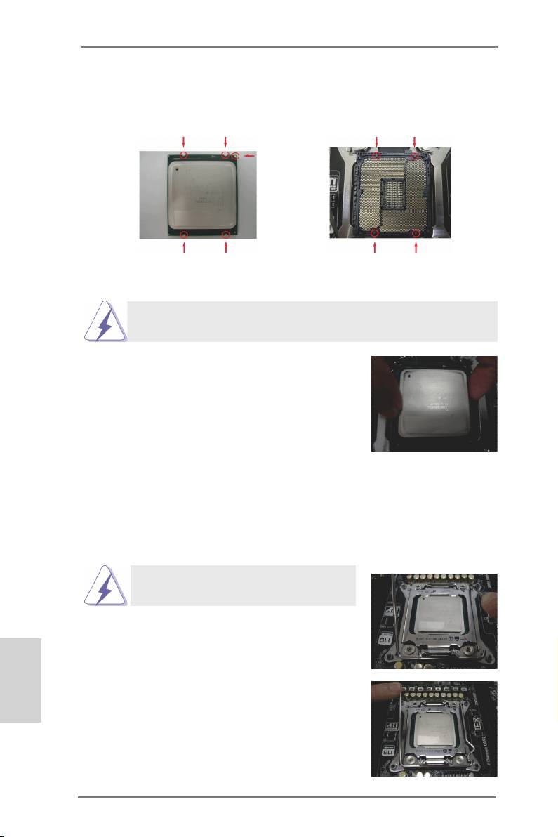
Below is an example to illustrate the installation of the heatsink for 2011-Pin CPUs.
Step 1. Apply thermal interface material onto center of
IHS on the socket’s surface.
Step 2. Place the heatsink onto the socket. Ensure
that the fan cables are oriented on side closest
to the CPU fan connector on the motherboard
(CPU_FAN1, see page 2, No. 7 or CPU_
FAN2, see page 2, No. 8).
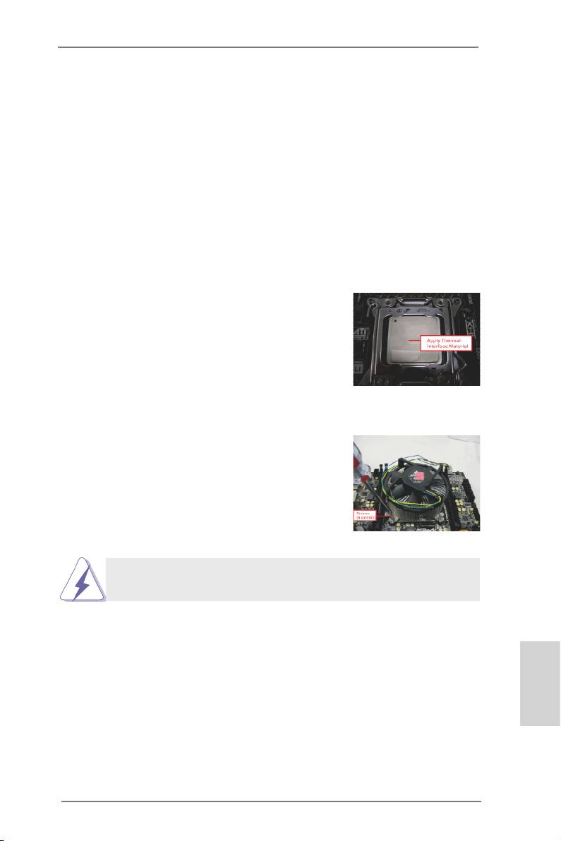
Step 3. Align screws with the motherboard’s holes.
Step 4. Use a screw driver to install the screws.
If you don’t fasten the screws, the heatsink cannot be secured on
the motherboard.
Step 5. Connect fan header with the CPU fan connector on the motherboard.
Step 6. Secure redundant cable with tie-wrap to ensure the cable does not
interfere with fan operation or contact other components.
English
15
X79 Extreme11 Motherboard

2.5 Installation of Memory Modules (DIMM)
This motherboard provides eight 240-pin DDR3 (Double Data Rate 3) DIMM
slots, and supports Quad Channel Memory Technology. For quad channel con-
guration, you always need to install identical (the same brand, speed, size
and chip-type) DDR3 DIMM in the slots, so that Quad Channel Memory Tech-
nology can be activated.
®
1. Due to Intel
CPU spec denition, please install the memory mod-
ules on DDR3_A1, DDR3_B1, DDR3_C1 and DDR3_D1 for first
priority. If the four DDR3 DIMM slots above are fully installed, and
you want to use more than four memory modules, please install the
other memory modules from left to right (from DDR3_A2, DDR3_
B2, DDR3_D2 to DDR3_C2.)
2. If only two memory modules are installed in the DDR3 DIMM slots,
then Dual Channel Memory Technology is activated. If three mem-
ory modules are installed, then Triple Channel Memory Technology
is activated. If more than four memory modules are installed in the
DDR3 DIMM slots, then Quad Channel Memory Technology is acti-
vated.
3. It is not allowed to install a DDR or DDR2 memory module into
DDR3 slot; otherwise, this motherboard and DIMM may be dam-
aged.
English
16
X79 Extreme11 Motherboard
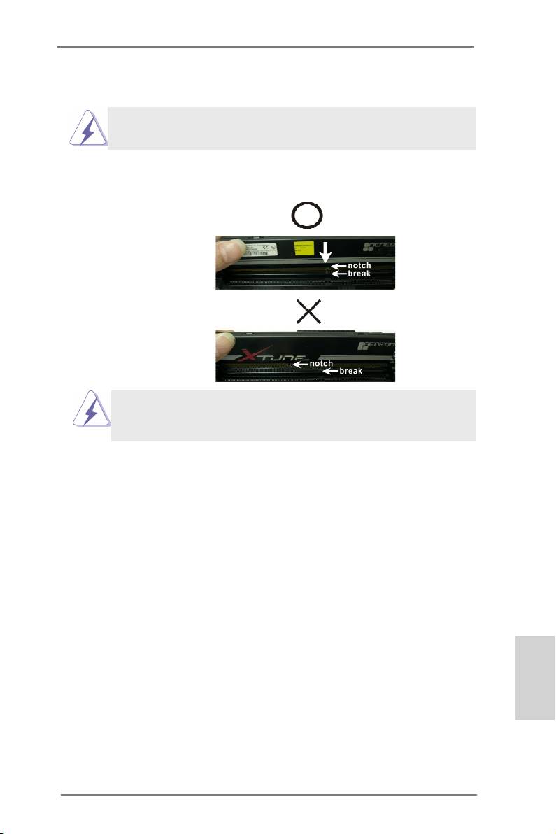
Installing a DIMM
Please make sure to disconnect power supply before adding or remov-
ing DIMMs or the system components.
Step 1. Unlock the DIMM slot by pressing the retaining clips outward.
Step 2. Align the DIMM on the slot such that the notch on the DIMM matches the
break on the slot.
The DIMM only ts in one correct orientation. It will cause permanent
damage to the motherboard and the DIMM if you force the DIMM into
the slot in incorrect orientation.
Step 3. Firmly insert the DIMM into the slot until the retaining clips at both ends
fully snap back in place and the DIMM is properly seated.
English
17
X79 Extreme11 Motherboard
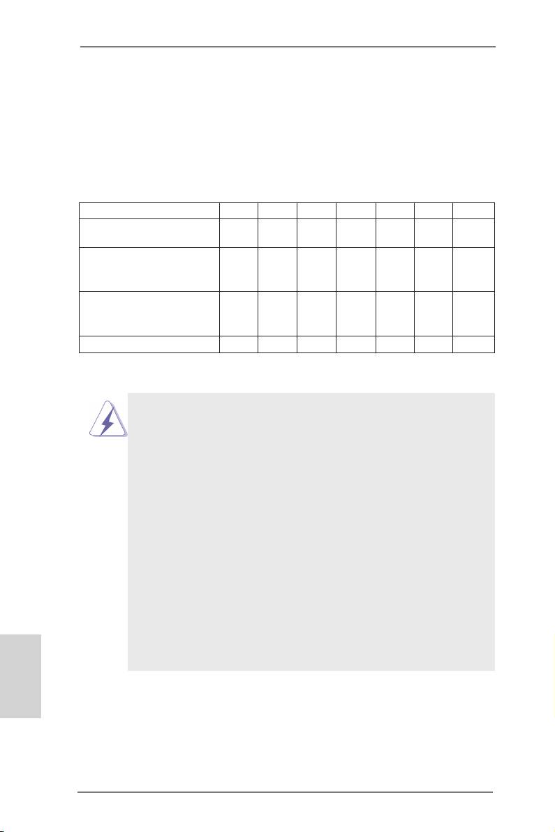
2.6 Expansion Slots (PCI and PCI Express Slots)
There are 7 PCI Express slots on this motherboard.
PCIE slots:PCIE1 / PCIE2 / PCIE3 / PCIE4 / PCIE5 / PCIE6 / PCIE7 (PCIE 3.0 x16
slots) are used for PCI Express graphics cards.
PCIE Slot Congurations
PCIE1 PCIE2 PCIE3 PCIE4 PCIE5 PCIE6 PCIE7
Two Graphics Cards in x16 N/A N/A N/A x16 N/A N/A
TM
TM
CrossFireX
or SLI
Mode
Three Graphics Cards in
TM
3-Way CrossFireX
or x16 N/A x16 N/A x16 N/A N/A
TM
3-Way SLI
Mode
Four Graphics Cards in
TM
4-Way CrossFireX
or x16 N/A x16 N/A x16 N/A x16
TM
4-Way SLI
Mode
Seven Graphics Cards x16 x8 x8 x8 x8 x8 x8
1. In single VGA card mode, it is recommended to install a PCI Express
x16 graphics card in the PCIE1 slot.
TM
TM
2. In CrossFireX
mode or SLI
mode, please install the PCI Express
x16 graphics cards in PCIE1 and PCIE5 slots. Both these two slots
will work at x16 bandwidth.
TM
TM
3. In 3-Way CrossFireX
or 3-Way SLI
mode, please install the PCI
Express x16 graphics cards in PCIE1, PCIE3 and PCIE5 slots.
PCIE1, PCIE3 and PCIE5 will work at x16 bandwidth.
TM
TM
4. In 4-Way CrossFireX
or 4-Way SLI
mode, please install the PCI
Express x16 graphics cards in PCIE1, PCIE3, PCIE5 and PCIE7
slots. PCIE1, PCIE3, PCIE5 and PCIE7 will work at x16 bandwidth.
5. Please connect a chassis fan to the motherboard’s chassis fan
connector (CHA_FAN1, CHA_FAN2 or CHA_FAN3) when using
multiple graphics cards for better thermal environment.
®
6. Currently Intel
Socket 2011 Sandy Bridge-E Processors don’t
support PCIE 3.0, but this motherboard is already PCIE 3.0 hardware
ready. It depends on Intel’s CPU to enable PCIE 3.0. Please check
English
Intel’s website for information on future CPU updates and releases.
18
X79 Extreme11 Motherboard

Installing an expansion card
Step 1. Before installing an expansion card, please make sure that the power
supply is switched off or the power cord is unplugged. Please read the
documentation of the expansion card and make necessary hardware
settings for the card before you start the installation.
Step 2. Remove the system unit cover (if your motherboard is already installed
in a chassis).
Step 3. Remove the bracket facing the slot that you intend to use. Keep the
screws for later use.
Step 4. Align the card connector with the slot and press rmly until the card is
completely seated on the slot.
Step 5. Fasten the card to the chassis with screws.
Step 6. Replace the system cover.
English
19
X79 Extreme11 Motherboard
2.7 ASRock Game Blaster Configuration
This section explains how to congure your ASRock Game Blaster.
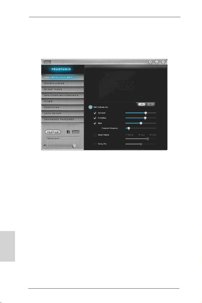
2.7.1 THX TRUSTUDIO PRO
THX TruStudio Pro
Click the power button on the left to activate or deactivate.
Surround
Control the level of audio immersion in music, movies and games.
Crystalizer
Enhance music and movies to make them sound livelier.
Bass
Control the desired level of bass.
Crossover Frequency
Redirect all frequencies below this value to the optimal speaker for
better bass response.
Smart Volume
Adjust the loudness of your audio playback automatically to minimize
English
sudden volume changes.
Dialog Plus
Enhance the voices in movies for clearer dialog.
20
X79 Extreme11 Motherboard
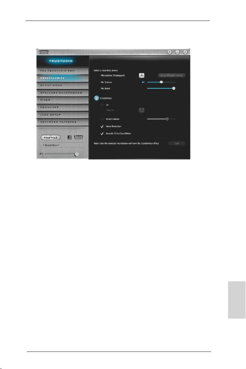
2.7.2 CRYSTALVOICE
Select a recording device
Mic Volume
Control the level of mic volume.
Mic Boost
Control the level of mic boost.
CrystalVoice
Click the power button on the left to activate or deactivate.
FX
Morph your voice into different characters and accents.
Smart Volume
Be heard clearly without having to shout or whisper.
Noise Reduction
Eliminate unwanted background noise in your conversation.
Acoustic Echo Cancellation
Eliminate echoes that interfere with your conversation.
English
21
X79 Extreme11 Motherboard
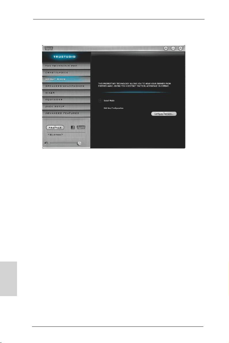
2.7.3 SCOUT MODE
Scout Mode
Enable or disable scout mode. This proprietary technology allows you to hear
your enemies from further away, giving you a distinct tactical advantage in
combat.
Hot Key Conguration
Congure hot keys to enable or disable scout mode.
English
22
X79 Extreme11 Motherboard
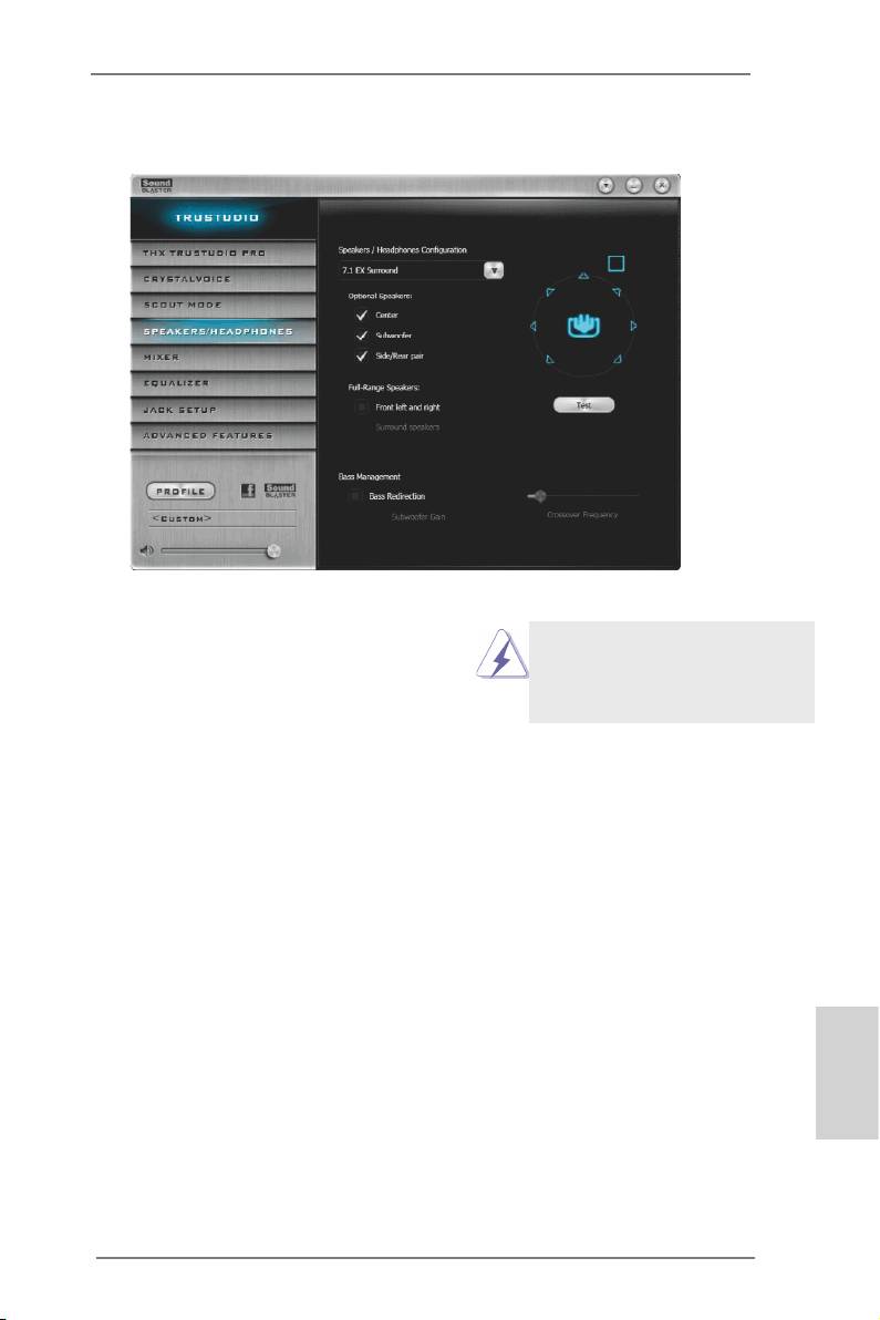
2.7.4 SPEAKERS/HEADPHONES
Speakers / Headphones Conguration
Select the device connected.
If there are both speakers and
Optional Speakers:
front headphones connected,
please select the device you
Center
desire to use as audio output.
Enable or disable center speaker.
Subwoofer
Enable or disable subwoofer.
Rear pair
Enable or disable rear pair speakers.
Full-Range Speakers:
Select full-range speakers.
Front left and right
Surround speakers
Bass Management
Bass Redirection
Enable or disable bass redirection.
Subwoofer Gain
English
Enable or disable subwoofer gain.
Crossover Frequency
Redirect all frequencies below this value to the optimal speaker for better
bass response.
23
X79 Extreme11 Motherboard
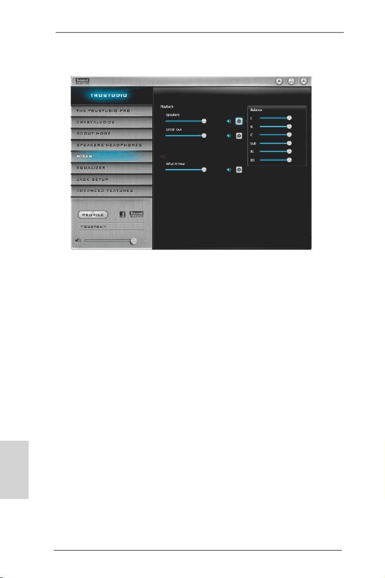
2.7.5 MIXER
Playback
Speakers
Control the level of speakers playback.
SPDIF-Out
Control the level of SPDIF-Out playback.
Balance
Control the level of various speaker’s balance.
REC
Input Device
Select input device.
What U Hear
Control the level of playback redirect.
English
24
X79 Extreme11 Motherboard
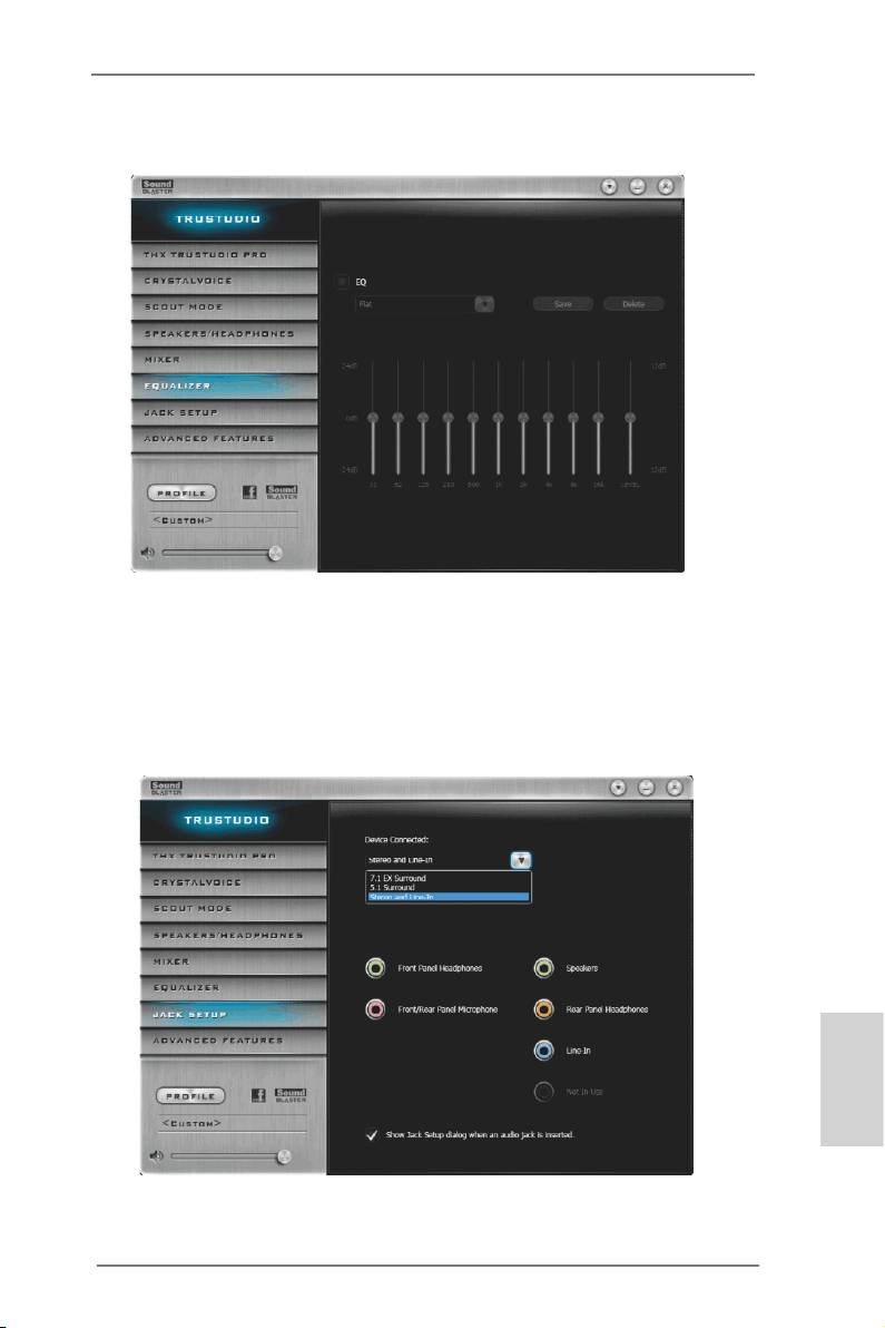
2.7.6 EQUALIZER
EQ
Choose from Flat, Acoustic, Classical, Country, Dance, Jazz, New Age, Pop,
Rock and Vocal.
2.7.7 JACK SETUP
English
25
X79 Extreme11 Motherboard
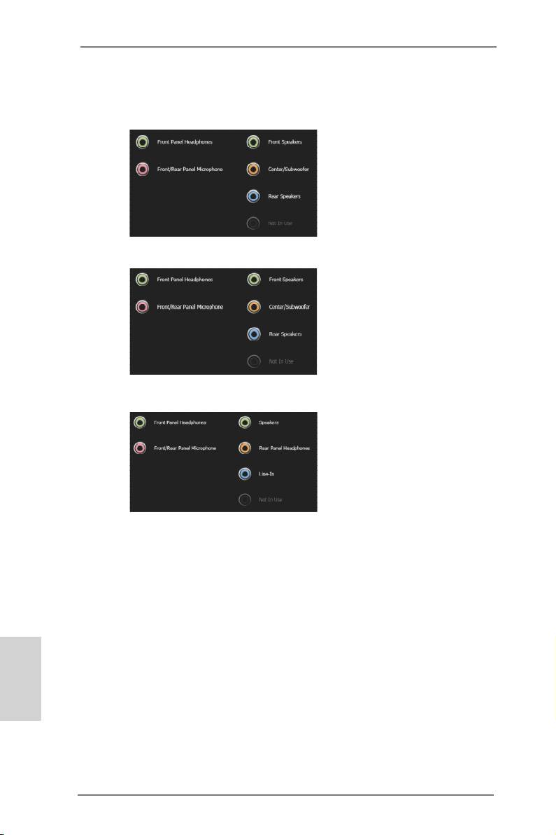
Device Connected:
Select the device connected.
5.1 Surround
7.1 EX Surround
Stereo and Line-In
Show Jack Setup dialog when an audio jack is inserted
Enable or disable Jack Setup dialog.
English
26
X79 Extreme11 Motherboard
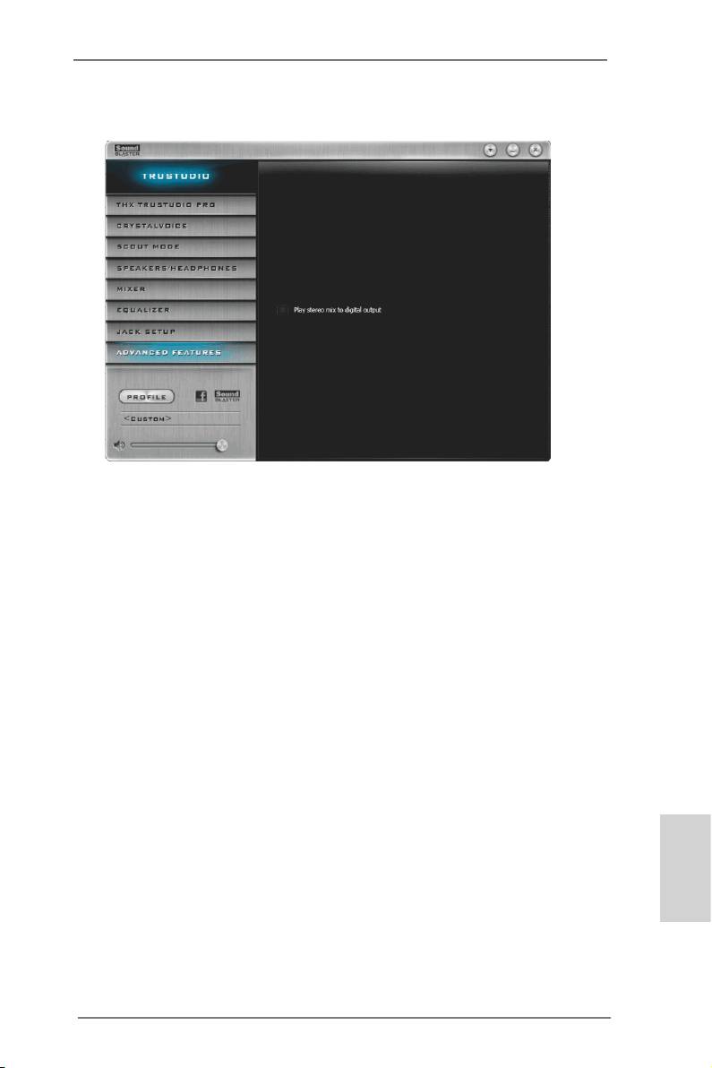
2.7.8 ADVANCED FEATURES
Play stereo mix to digital output
Enable or disable play stereo mix to digital output.
English
27
X79 Extreme11 Motherboard
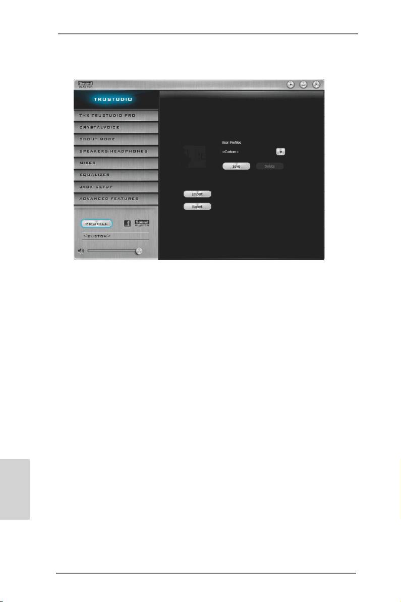
2.7.9 PROFILE
User Proles
You can save, load or delete your user proles. The default is <Custom>.
English
28
X79 Extreme11 Motherboard
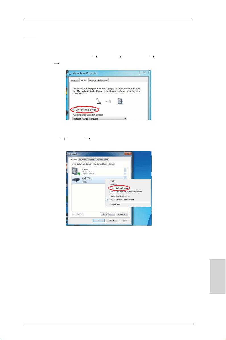
Note
1. If you want to hear your own voice through the microphone (Playback mode). You
can change your settings to "playback mode" by checking the "Listen to this
device" box in Control panel Sound Recording Microphone
Properties Listen.
2. If you want to change your playback device to a SPDIF-Out device, go into
Control panel Sound Playback, then right click on SPDIF-Out and
check the "Set as Default Device" option.
English
29
X79 Extreme11 Motherboard
TM
TM
TM
TM
2.8 SLI
, 3-Way SLI
, 4-Way SLI
and Quad SLI
Operation
Guide
®
TM
TM
TM
This motherboard supports NVIDIA
SLI
, 3-Way SLI
, 4-Way SLI
and Quad
TM
SLI
(Scalable Link Interface) technology that allows you to install up to four
®
TM
identical PCI Express x16 graphics cards. Currently, NVIDIA
SLI
technology
®
TM
TM
®
TM
supports Windows
Vista
/ Vista
64-bit / 7 / 7 64-bit OS. NVIDIA
3-Way SLI
,
TM
TM
®
TM
TM
4-Way SLI
and Quad SLI
technology supports Windows
Vista
/ Vista
64-bit
/ 7 / 7 64-bit OS only. Please follow the installation procedures in this section.
Requirements
TM
TM
1. For SLI
technology, you should have two identical SLI
-ready graphics
®
TM
cards that are NVIDIA
certied. For 3-Way SLI
technology you should
TM
have three, whereas for 4-Way SLI
technology you should have four. For
TM
TM
Quad SLI
technology, you should have two identical Quad SLI
-ready
®
graphics cards that are NVIDIA
certied.
®
TM
2. Make sure that your graphics card driver supports NVIDIA
SLI
technology
(driver version 280.41 and later). Download the driver from NVIDIA website
(www.nvidia.com).
3. Make sure that your power supply unit (PSU) can provide at least the
®
minimum power required by your system. It is recommended to use NVIDIA
®
certied PSU. Please refer to NVIDIA
website for details.
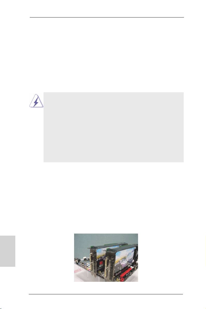
2.8.1 Graphics Card Setup
TM
2.8.1.1 Installing Two SLI
-Ready Graphics Cards
TM
®
Step 1. Install identical SLI
-ready graphics cards that are NVIDIA
certied be-
cause different types of graphics cards will not work together properly. (Even
the GPU chips version shall be the same.) Insert one graphics card into
PCIE1 slot and the other graphics card to PCIE5 slot. Make sure that the
cards are properly seated on the slots.
English
30
X79 Extreme11 Motherboard
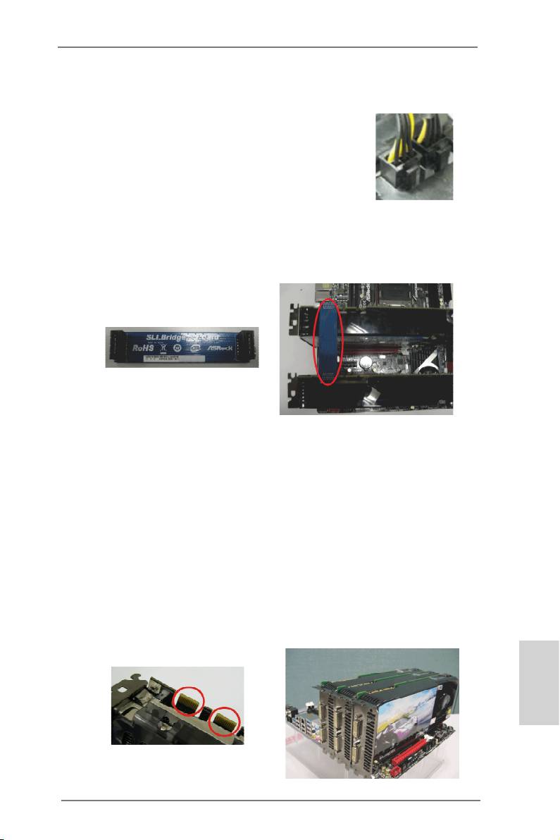
Step2. If required, connect the auxiliary power source to the PCI Express graph-
ics cards.
Step3. Align and insert the ASRock SLI_Bridge_3S Card to the goldngers on
each graphics card. Make sure the ASRock SLI_Bridge_3S Card is rmly
in place.
ASRock SLI_Bridge_3S Card
Step4. Connect a VGA cable or a DVI cable to the monitor connector or the DVI
connector of the graphics card that is inserted to PCIE1 slot.
TM
2.8.1.2 Installing Three SLI
-Ready Graphics Cards
TM
®
Step 1. Install identical 3-Way SLI
-ready graphics cards that are NVIDIA
certi-
ed because different types of graphics cards will not work together prop-
erly. (Even the GPU chips version shall be the same.) Each graphics card
should have two goldngers for the 3-Way SLI Bridge connector. Insert
one graphics card into PCIE1 slot, another graphics card to PCIE3 slot,
and the other graphics card to PCIE5 slot. Make sure that the cards are
properly seated on the slots.
English
Two Goldngers
31
X79 Extreme11 Motherboard
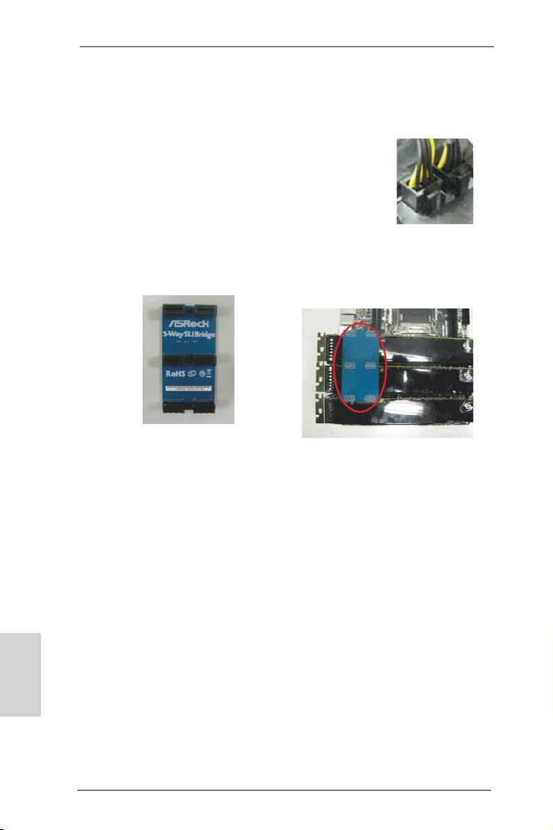
Step2. Connect the auxiliary power source to the PCI Express graphics card.
Please make sure that both power connectors on the PCI Express graph-
ics card are connected. Repeat this step on the three graphics cards.
Step3. Align and insert the ASRock 3-Way SLI Bridge Card to the goldfingers
on each graphics card. Make sure the ASRock 3-Way SLI Bridge Card is
rmly in place.
ASRock 3-Way SLI Bridge Card
Step4. Connect a VGA cable or a DVI cable to the monitor connector or the DVI
connector of the graphics card that is inserted to PCIE1 slot.
English
32
X79 Extreme11 Motherboard
TM
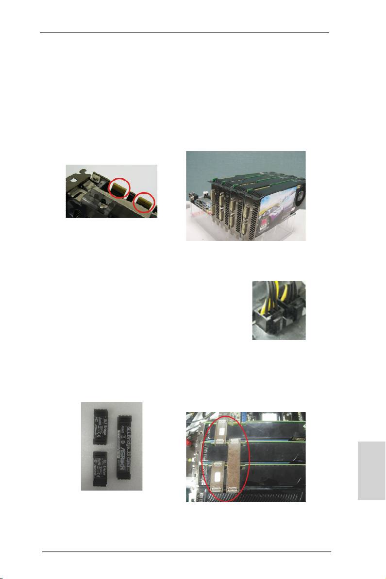
2.8.1.3 Installing Four SLI
-Ready Graphics Cards
TM
®
Step 1. Install identical 4-Way SLI
-ready graphics cards that are NVIDIA
certi-
ed because different types of graphics cards will not work together prop-
erly. (Even the GPU chips version shall be the same.) Each graphics card
should have two goldngers for the ASRock SLI Bridge Card connectors.
Insert one graphics card into the PCIE1 slot, another graphics card into the
PCIE3 slot, the third graphics card into the PCIE5 slot and the last graph-
ics card into the PCIE7 slot. Make sure that the cards are properly seated
on the slots.
Two Goldngers
Step2. Connect the auxiliary power source to the PCI Express graphics card.
Please make sure that both power connectors on the PCI Express graph-
ics card are connected. Repeat this step on the other graphics cards.
Step3. Align and insert an ASRock SLI Bridge Card to the goldngers of the rst
and second graphics card. Install the second ASRock SLI Bridge Card to
the goldngers of the third and fourth graphics card. Connect the second
and the fourth graphics card with the ASRock SLI_Bridge_3S Card. Make
sure the ASRock SLI Bridge Cards are rmly in place.
English
2 ASRock SLI_Bridge Cards
and an ASRock SLI_Bridge_3S Card
Step4. Connect a VGA cable or a DVI cable to the monitor connector or the DVI
connector of the graphics card that is inserted to PCIE1 slot.
33
X79 Extreme11 Motherboard
2.8.2 Driver Installation and Setup
Install the graphics card drivers to your system. After that, you can enable the Multi-
®
Graphics Processing Unit (GPU) feature in the NVIDIA
nView system tray utility.
Please follow the below procedures to enable the multi-GPU feature.
®
TM
TM
For Windows
Vista
/ Vista
64-bit / 7 / 7 64-bit OS:
TM
TM
(For SLI
and Quad SLI
mode)
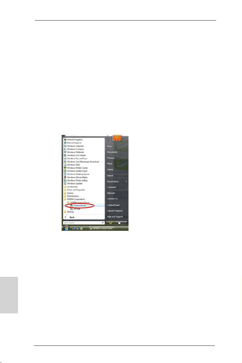
A. Click the Start icon on your Windows taskbar.
B. From the pop-up menu, select All Programs, and then click NVIDIA
Corporation.
C. Select NVIDIA Control Panel tab.
D. Select Control Panel tab.
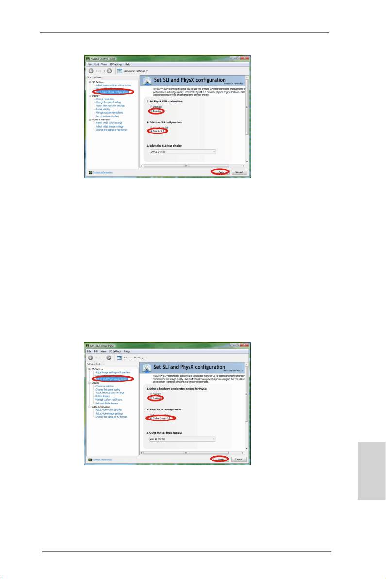
E. From the pop-up menu, select Set SLI and PhysX conguration. In
Set PhysX GPU acceleration item, please select Enabled.
F. In Select an SLI conguration item, please select Enable SLI. And
click Apply.
English
34
X79 Extreme11 Motherboard
G. Reboot your system.
TM
TM
H. You can freely enjoy the benets of SLI
or Quad SLI
.
®
TM
TM
For Windows
Vista
/ Vista
64-bit / 7 / 7 64-bit OS:
TM
TM
(For 3-Way SLI
or 4-Way SLI
mode)
A. Follow steps A to E on page 34.
B. In Select an SLI conguration item, please select Enable 3-way SLI
or Enable 4-way SLI and click Apply.
C. Reboot your system.
English
TM
TM
D. You can freely enjoy the benets of 3-Way SLI
or 4-Way SLI
.
TM
®
* SLI
appearing here is a registered trademark of NVIDIA
Technologies Inc., and is used only
for identication or explanation and to the owners’ benet, without intent to infringe.
35
X79 Extreme11 Motherboard
TM
TM
TM
2.9 CrossFireX
, 3-Way CrossFireX
, 4-Way CrossFireX
and
TM
Quad CrossFireX
Operation Guide
TM
TM
TM
This motherboard supports CrossFireX
, 3-way CrossFireX
, 4-way CrossFireX
TM
TM
and Quad CrossFireX
. CrossFireX
technology offers the most advantageous
means available of combining multiple high performance Graphics Processing
Units (GPU) in a single PC. Combining a range of different operating modes with
TM
intelligent software design and an innovative interconnect mechanism, CrossFireX
enables the highest possible level of performance and image quality in any 3D
TM
®
TM
application. Currently CrossFireX
is supported with Windows
Vista
/ 7 OS.
TM
TM
TM
3-way CrossFireX
, 4-way CrossFireX
and Quad CrossFireX
are supported
®
TM
TM
with Windows
Vista
/ 7 OS only. Please check AMD’s website for CrossFireX
driver updates.
1. If a customer incorrectly congures their system they will not see the performance
TM
TM
TM
benets of CrossFireX
. All three CrossFireX
components, a CrossFireX
TM
TM
Ready graphics card, a CrossFireX
Ready motherboard and a CrossFireX
Edition co-processor graphics card, must be installed correctly to benet from the
TM
CrossFireX
multi-GPU platform.
TM
2. If you pair a 12-pipe CrossFireX
Edition card with a 16-pipe card, both cards
TM
will operate as 12-pipe cards while in CrossFireX
mode.
2.9.1 Graphics Card Setup
TM
2.9.1.1 Installing Two CrossFireX
-Ready Graphics Cards
TM
TM
Different CrossFireX
cards may require different methods to enable CrossFireX
TM
feature. For other CrossFireX
cards that AMD has released or will release in the
future, please refer to AMD graphics card manuals for detailed installation guide.
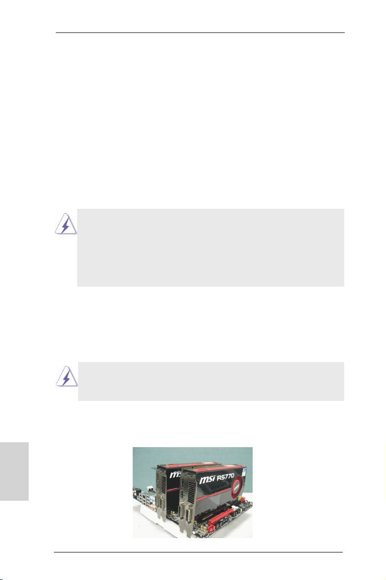
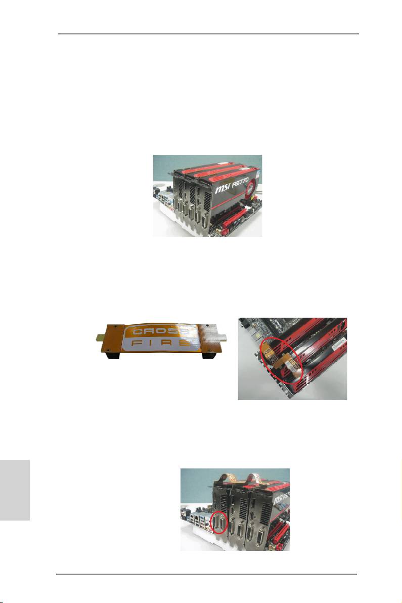
Step 1. Insert one Radeon graphics card into PCIE1 slot and the other Radeon
graphics card to PCIE5 slot. Make sure that the cards are properly seated
on the slots.
English
36
X79 Extreme11 Motherboard
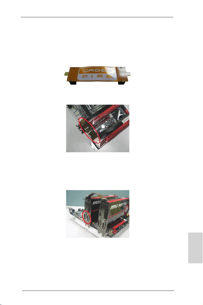
Step 2. Connect two Radeon graphics cards by installing a CrossFire Bridge on
the CrossFire Bridge Interconnects on the top of the Radeon graphics
cards. (The CrossFire Bridge is provided with the graphics card you pur-
chase, not bundled with this motherboard. Please refer to your graphics
card vendor for details.)
CrossFire Bridge
Step 3. Connect the DVI monitor cable to the DVI connector on the Radeon graph-
ics card on PCIE1 slot. (You may use the DVI to D-Sub adapter to convert
the DVI connector to D-Sub interface, and then connect the D-Sub monitor
cable to the DVI to D-Sub adapter.)
English
37
X79 Extreme11 Motherboard
TM
2.9.1.2 Installing Three CrossFireX
-Ready Graphics Cards
TM
®
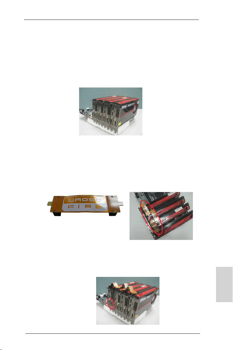
Step 1. Install identical 3-Way CrossFireX
-ready graphics cards that are AMD
certied because different types of graphics cards will not work together
properly. (Even the GPU chips version shall be the same.) Insert one
graphics card into PCIE1 slot, another graphics card to PCIE3 slot, and
the other graphics card to PCIE5 slot. Make sure that the cards are prop-
erly seated on the slots.
TM
Step 2. Use one CrossFire
Bridge to connect the Radeon graphics cards on
TM
PCIE1 and PCIE3 slots, and use the other CrossFire
Bridge to connect
TM
the Radeon graphics cards on PCIE3 and PCIE5 slots. (The CrossFire
Bridge is provided with the graphics card you purchase, not bundled with
this motherboard. Please refer to your graphics card vendor for details.)
TM
CrossFire
Bridge
Step 3. Connect the DVI monitor cable to the DVI connector on the Radeon graph-
ics card on PCIE1 slot. (You may use the DVI to D-Sub adapter to convert
the DVI connector to D-Sub interface, and then connect the D-Sub monitor
cable to the DVI to D-Sub adapter.)
English
38
X79 Extreme11 Motherboard
TM
2.9.1.3 Installing Four CrossFireX
-Ready Graphics Cards
TM
®
Step 1. Install identical 4-Way CrossFireX
-ready graphics cards that are AMD
certied because different types of graphics cards will not work together
properly. (Even the GPU chips version shall be the same.) Insert one
graphics card into PCIE1 slot, another graphics card into PCIE3 slot, the
third graphics card into PCIE5 slot and the last graphics card into PCIE7
slot. Make sure that the cards are properly seated on the slots.
TM
Step 2. Use one CrossFire
Bridge to connect the Radeon graphics cards on
TM
PCIE1 and PCIE3 slots, another CrossFire
Bridge to connect the Rad-
eon graphics cards on PCIE3 and PCIE5 slots, and use the third Cross-
TM
Fire
Bridge to connect the Radeon graphics cards on PCIE5 and PCIE7
TM
slots. (The CrossFire
Bridge is provided with the graphics card you pur-
chase, not bundled with this motherboard. Please refer to your graphics
card vendor for details.)
TM
CrossFire
Bridge
Step 3. Connect the DVI monitor cable to the DVI connector on the Radeon graph-
ics card on PCIE1 slot. (You may use the DVI to D-Sub adapter to convert
the DVI connector to D-Sub interface, and then connect the D-Sub monitor
cable to the DVI to D-Sub adapter.)
English
39
X79 Extreme11 Motherboard
2.9.2 Driver Installation and Setup
Step 1. Power on your computer and boot into OS.
Step 2. Remove the AMD drivers if you have any VGA drivers installed in your
system.
The Catalyst Uninstaller is an optional download. We recommend using this utility to
uninstall any previously installed Catalyst drivers prior to installation.
Please check AMD’s website for AMD driver updates.
Step 3. Install the required drivers to your system.
®
TM
For Windows
7 / Vista
OS:
Install the CATALYST Control Center. Please check AMD’s website for
details.
Step 4. Restart your computer.
Step 5. Install the VGA card drivers to your system, and restart your computer.
®
You will nd “AMD Catalyst Control Center” on your Windows
taskbar.
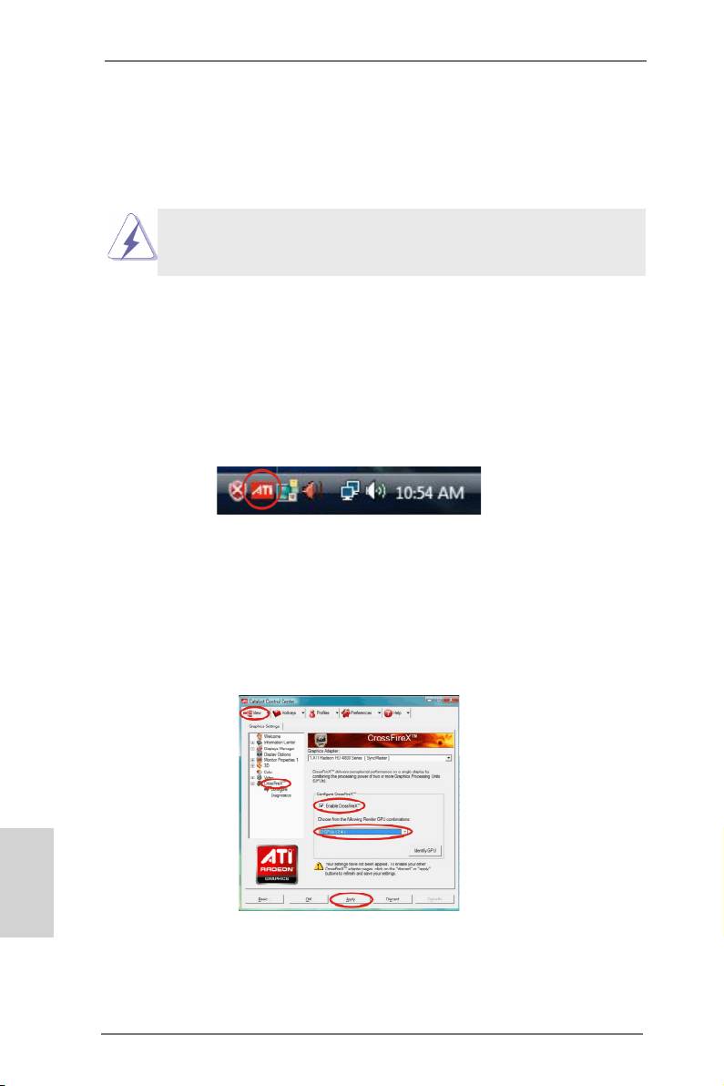
AMD Catalyst Control Center
Step 6. Double-click “ATI Catalyst Control Center”. Click “View”, select “CrossFi-
TM
TM
reX
”, and then check the item “Enable CrossFireX
”. Select “2 GPUs”
and click “Apply” (if you install two Radeon graphics cards). Select “3
GPUs” and click “OK” (if you install three Radeon graphics cards). Select “4
GPUs” and click “OK” (if you install four Radeon graphics cards).
English
40
X79 Extreme11 Motherboard

TM
TM
Although you have selected the option “Enable CrossFire
”, the CrossFireX
function may not work actually. Your computer will automatically reboot. After
TM
restarting your computer, please conrm whether the option “Enable CrossFire
” in
“AMD Catalyst Control Center” is selected or not; if not, please select it again, and
TM
then you are able to enjoy the benets of CrossFireX
.
TM
TM
Step 7. You can freely enjoy the benets of CrossFireX
, 3-Way CrossFireX
,
TM
TM
4-Way CrossFireX
or Quad CrossFireX
.
TM
* CrossFireX
appearing here is a registered trademark of AMD Technologies Inc., and is used
only for identication or explanation and to the owners’ benet, without intent to infringe.
TM
* For further information of AMD CrossFireX
technology, please check AMD’s website for
updates and details.
2.10 Surround Display Feature
This motherboard supports Surround Display upgrade. With the external add-on PCI
Express VGA cards, you can easily enjoy the benets of Surround Display feature.
For detailed instructions, please refer to the document at the following path in the
Support CD:
..\ Surround Display Information
English
41
X79 Extreme11 Motherboard
2.11 ASRock Smart Remote Installation Guide
ASRock Smart Remote is only used for ASRock motherboards with a CIR header.
Please refer to the procedures below for the quick installation and usage of ASRock
Smart Remote.
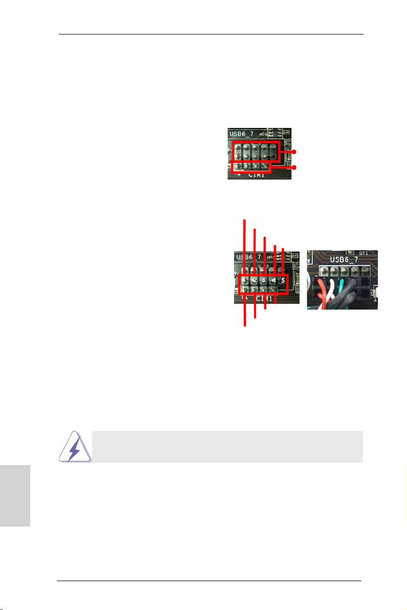
Step1. Find the CIR header located next
to the USB 2.0 header on your
USB 2.0 header (9-pin, black)
ASRock motherboard.
CIR header (4-pin, gray)
USB_PWR
Step2. Connect the front USB cable to the
P-
USB 2.0 header (as below, pin 1-5)
P+
and the CIR header. Please make
GND
DUMMY
sure the wire assignments and the
pin assignments are matched
correctly.
GND
IRTX
IRRX
ATX+5VSB
Step3. Install the Multi-Angle CIR Receiver to the front USB port.
Step4. Boot up your system. Press <F2> or <Del> to enter the BIOS Setup Utility.
Make sure the option "CIR Controller" is set to [Enabled].
(Advanced -> Super IO Conguration -> CIR Controller -> [Enabled])
If you cannot nd this option, please shut down your system and install
the Multi-Angle CIR Receiver to the other front USB port then try again.
English
Step5. Enter Windows. Execute ASRock's support CD and install the CIR Driver.
(It is listed at the bottom of driver list.)
42
X79 Extreme11 Motherboard
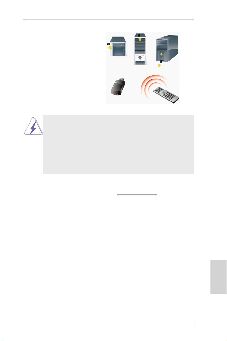
3 CIR sensors in different angles
1. Only one of the front USB ports can support CIR. When CIR is
enabled, the other ports will remain USB ports.
2. The Multi-Angle CIR Receiver is used for the front USB only.
Please do not use the rear USB bracket to connect it on the rear
panel. The Multi-Angle CIR Receiver can receive multi-directional
infrared signals (top, down and front), which is compatible with
most of the chassis on the market.
3. The Multi-Angle CIR Receiver does not support Hot-Plug. Please
install it before you boot the system.
* ASRock Smart Remote is only supported by some ASRock motherboards. Please refer to
ASRock's website for the motherboard support list: http://www.asrock.com
English
43
X79 Extreme11 Motherboard
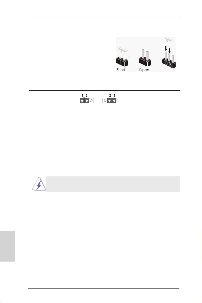
2.12 Jumpers Setup
The illustration shows how jumpers are
setup. When the jumper cap is placed on
pins, the jumper is “Short”. If no jumper cap
is placed on pins, the jumper is “Open”. The
illustration shows a 3-pin jumper whose
pin1 and pin2 are “Short” when jumper cap
is placed on these 2 pins.
Jumper Setting Description
Clear CMOS Jumper
(CLRCMOS1)
(see p.2, No. 38)
Clear CMOSDefault
Note: CLRCMOS1 allows you to clear the data in CMOS. To clear and reset the sys-
tem parameters to default setup, please turn off the computer and unplug the
power cord from the power supply. After waiting for 15 seconds, use a jumper
cap to short pin2 and pin3 on CLRCMOS1 for 5 seconds. However, please do
not clear the CMOS right after you update the BIOS. If you need to clear the
CMOS when you just nish updating the BIOS, you must boot up the system
rst, and then shut it down before you do the clear-CMOS action. Please be
noted that the password, date, time, user default prole, 1394 GUID and MAC
address will be cleared only if the CMOS battery is removed.
The Clear CMOS Switch has the same function as the Clear CMOS
jumper.
English
44
X79 Extreme11 Motherboard
2.13 Onboard Headers and Connectors
Onboard headers and connectors are NOT jumpers. Do NOT place
jumper caps over these headers and connectors. Placing jumper caps
over the headers and connectors will cause permanent damage of the
motherboard!
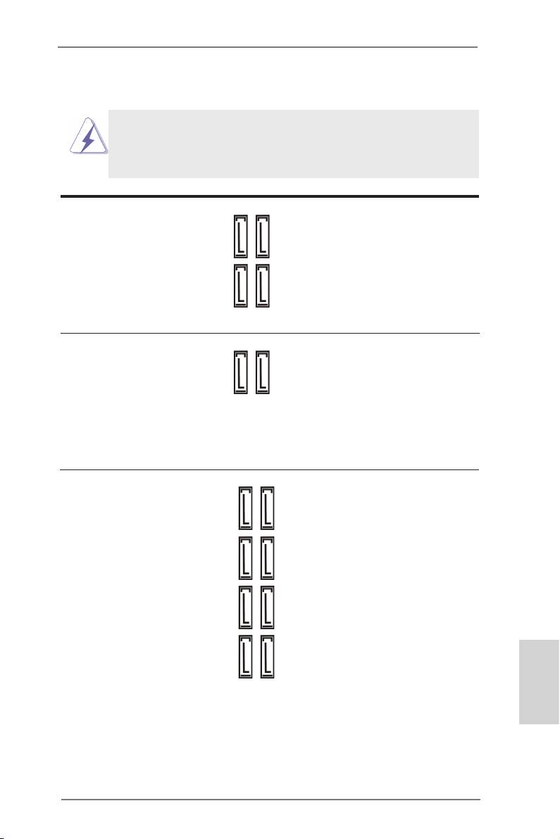
Serial ATA2 Connectors These four Serial ATA2 (SATA2)
(SATA2_0_1: see p.2, No. 18)
connectors support SATA data
(SATA2_2_3: see p.2, No. 19)
cables for internal storage
devices. The current SATA2
interface allows up to 3.0 Gb/s
data transfer rate.
SATA2_3 SATA2_1
SATA2_2 SATA2_0
Serial ATA3 Connectors These two Serial ATA3 (SATA3)
(SATA3_0_1: see p.2, No. 17)
connectors support SATA data
SATA3_1
SATA3_0
cables for internal storage
devices. The current SATA3
interface allows up to 6.0 Gb/s
data transfer rate.
SAS/Serial ATA3 Connectors These eight SAS/Serial ATA3
(SAS_0_1: see p.2, No. 20)
(SATA3) connectors support
(SAS_2_3: see p.2, No. 21)
SAS/SATA data cables for
(SAS_4_5: see p.2, No. 22)
internal storage devices. The
(SAS_6_7: see p.2, No. 23)
current SAS/SATA3 interface
allows up to 6.0 Gb/s data
SAS_3 SAS_1
SAS_2 SAS_0
transfer rate. We recommend
®
using Intel
X79 SATA2 ports
instead of SAS ports for your
ODDs. For connecting SAS
HDDs, please contact SAS data
SAS_7 SAS_5
SAS_6 SAS_4
cable dealers.
English
45
X79 Extreme11 Motherboard
Serial ATA (SATA) Either end of the SATA data
Data Cable cable can be connected to the
(Optional)
SATA / SATA2 / SATA3 hard
disks or the SATA2 / SATA3 /
SAS connectors on this
motherboard.
Serial ATA (SATA) Please connect the black end of
Power Cable the SATA power cable to the
(Optional)
power connector on each drive.
connect to the SATA
Then connect the white end of
HDD power connector
the SATA power cable to the
connect to the
power supply
power connector of the power
supply.
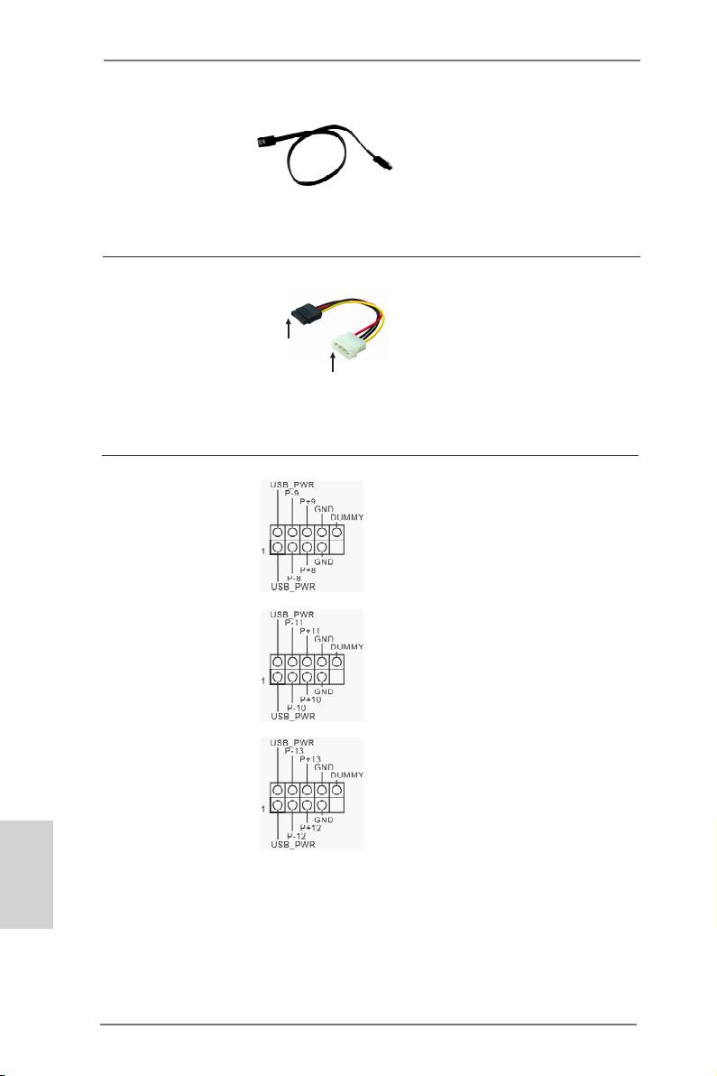
USB 2.0 Headers Besides eight default USB 2.0
(9-pin USB_8_9)
ports on the I/O panel, there are
(see p.2, No. 26)
three USB 2.0 headers on this
motherboard. Each USB 2.0
header can support two USB 2.0
ports.
(9-pin USB_10_11)
(see p.2, No. 29)
(9-pin USB_12_13)
(see p.2, No. 31)
English
46
X79 Extreme11 Motherboard
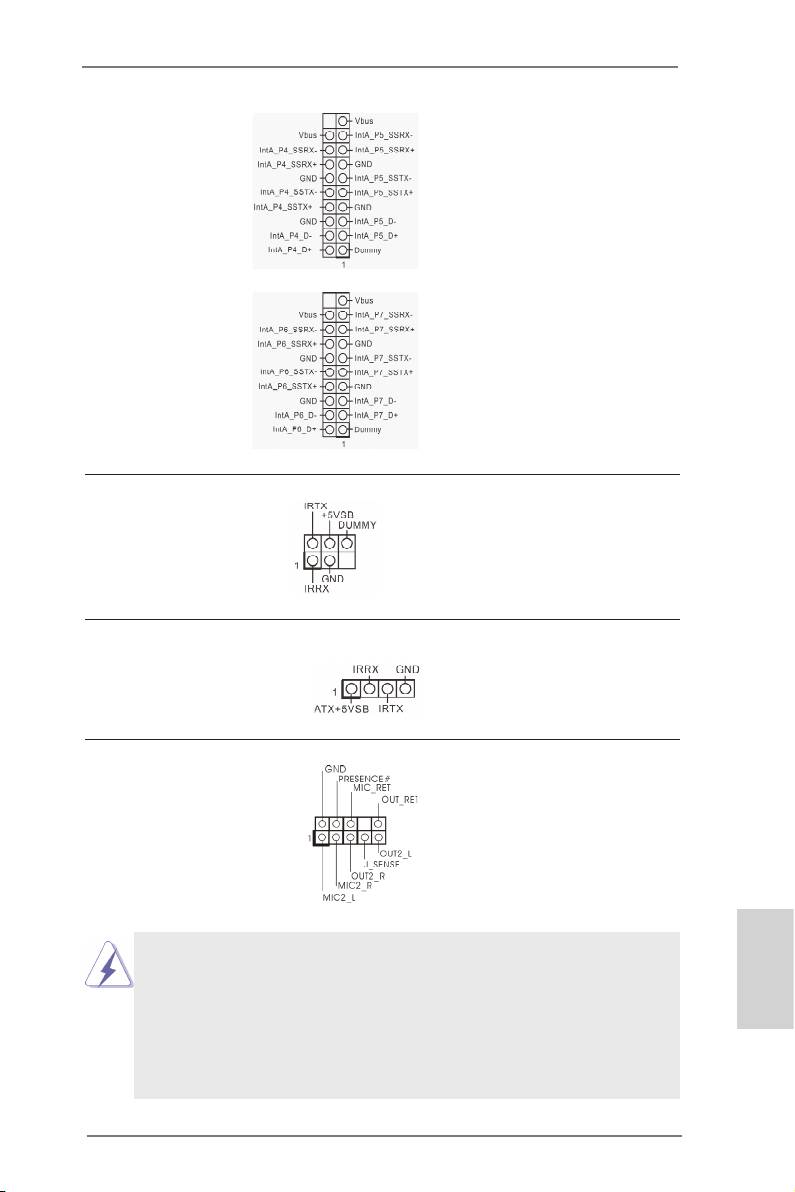
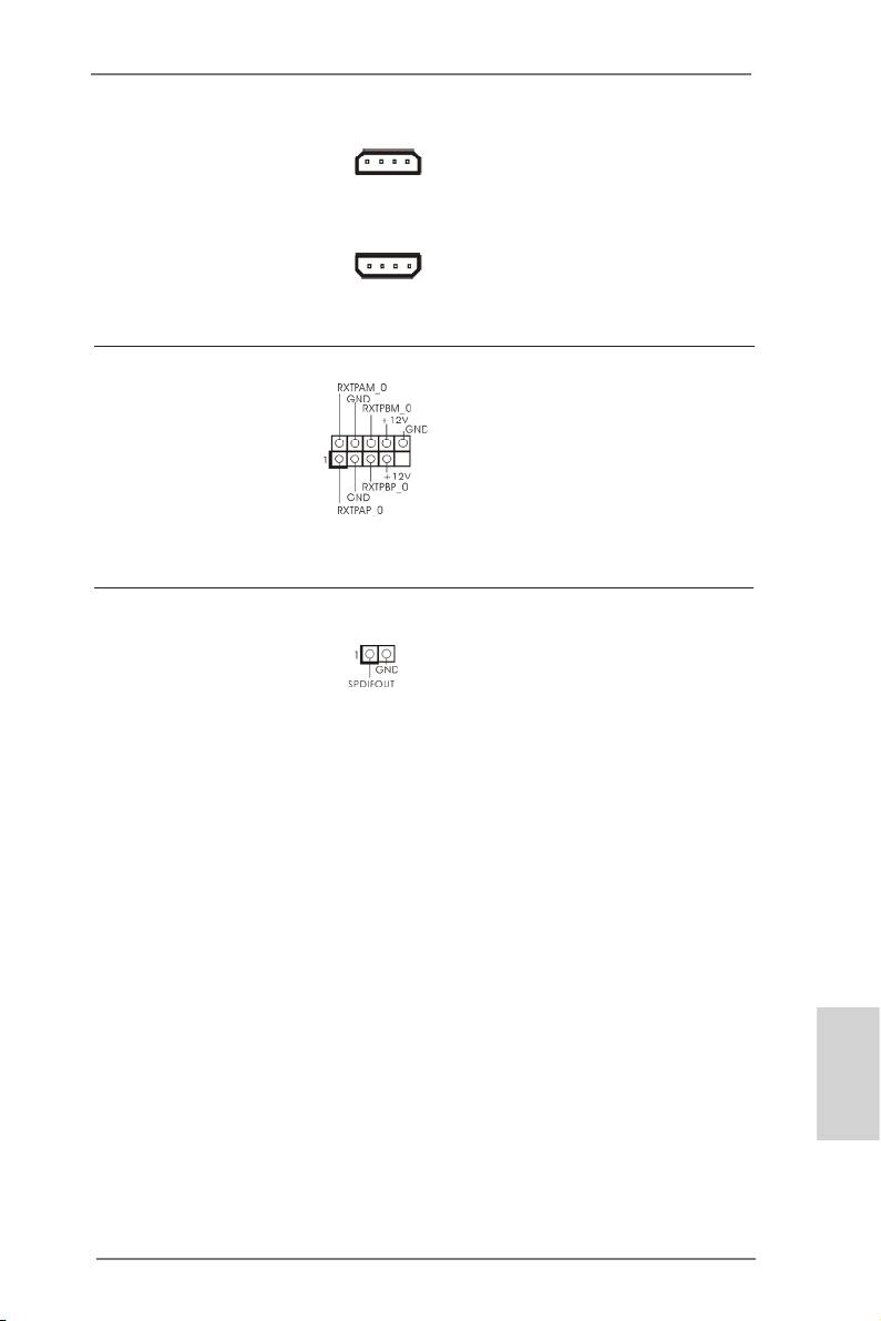
USB 3.0 Header Besides four default USB 3.0
(19-pin USB3_4_5)
ports on the I/O panel, there are
(see p.2, No. 12)
two USB 3.0 headers on this
motherboard. Each USB 3.0
header can support two USB 3.0
ports.
(19-pin USB3_6_7)
(see p.2, No. 13)
Infrared Module Header This header supports an
(5-pin IR1)
optional wireless transmitting
(see p.2, No. 39)
and receiving infrared module.
Consumer Infrared Module Header This header can be used to
(4-pin CIR1)
connect the remote controller
(see p.2, No. 27)
receiver.
Front Panel Audio Header This is an interface for front
(9-pin HD_AUDIO1)
panel audio cable that allows
(see p.2, No. 41)
convenient connection and
control of audio devices.
1. High Denition Audio supports Jack Sensing, but the panel wire on the
chassis must support HDA to function correctly. Please follow the
instruction in our manual and chassis manual to install your system.
English
2. If you use AC’97 audio panel, please install it to the front panel audio
header as below:
A. Connect Mic_IN (MIC) to MIC2_L.
B. Connect Audio_R (RIN) to OUT2_R and Audio_L (LIN) to OUT2_L.
47
X79 Extreme11 Motherboard
C. Connect Ground (GND) to Ground (GND).
D. MIC_RET and OUT_RET are for HD audio panel only. You don’t
need to connect them for AC’97 audio panel.
E. To activate the front mic.
®
For Windows
XP / XP 64-bit OS:
Select “Mixer”. Select “Recorder”. Then click “FrontMic”.
®
TM
TM
For Windows
7 / 7 64-bit / Vista
/ Vista
64-bit OS:
Go to the “FrontMic” Tab in the Realtek Control panel. Adjust
“Recording Volume”.
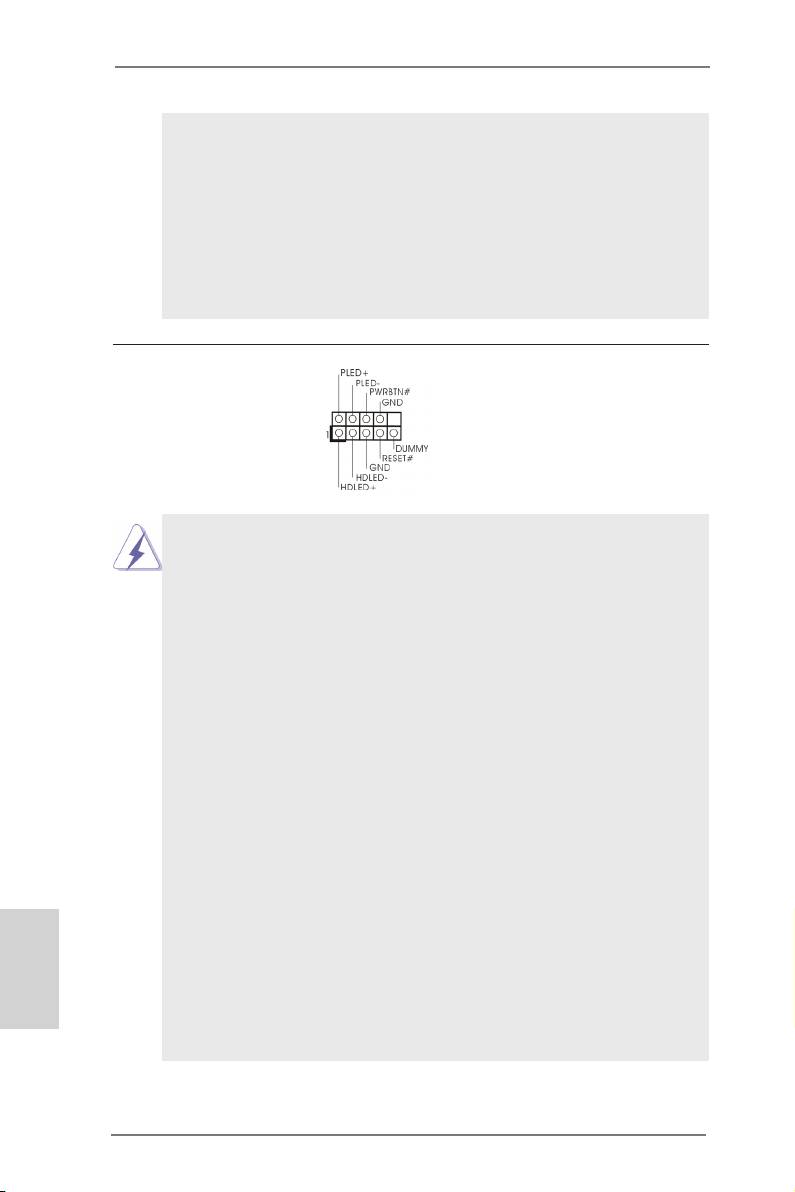
System Panel Header This header accommodates
(9-pin PANEL1)
several system front panel
(see p.2, No. 36)
functions.
Connect the power switch, reset switch and system status indicator on the
chassis to this header according to the pin assignments below. Note the
positive and negative pins before connecting the cables.
PWRBTN (Power Switch):
Connect to the power switch on the chassis front panel. You may congure
the way to turn off your system using the power switch.
RESET (Reset Switch):
Connect to the reset switch on the chassis front panel. Press the reset
switch to restart the computer if the computer freezes and fails to perform a
normal restart.
PLED (System Power LED):
Connect to the power status indicator on the chassis front panel. The LED
is on when the system is operating. The LED keeps blinking when the sys-
tem is in S1/S3 sleep state. The LED is off when the system is in S4 sleep
state or powered off (S5).
HDLED (Hard Drive Activity LED):
Connect to the hard drive activity LED on the chassis front panel. The LED
is on when the hard drive is reading or writing data.
English
The front panel design may differ by chassis. A front panel module mainly
consists of power switch, reset switch, power LED, hard drive activity LED,
speaker and etc. When connecting your chassis front panel module to this
header, make sure the wire assignments and the pin assign-ments are
matched correctly.
48
X79 Extreme11 Motherboard
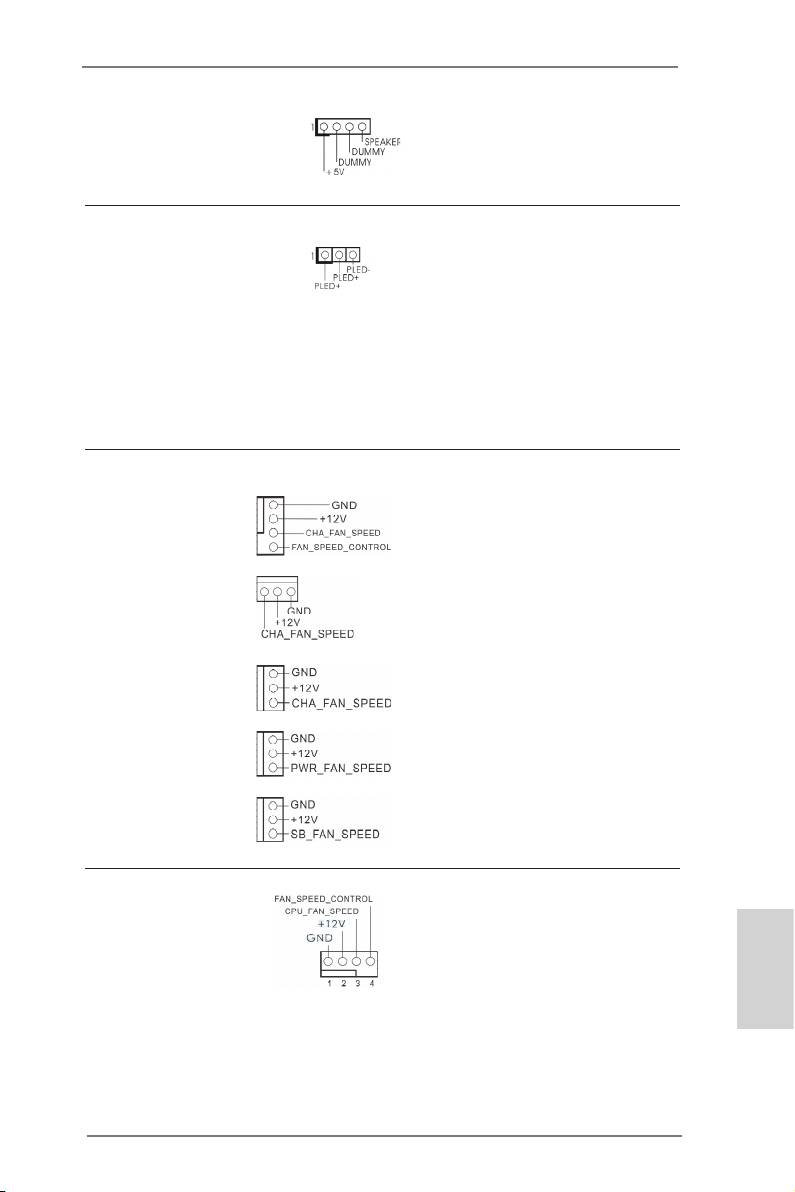
Chassis Speaker Header Please connect the chassis
(4-pin SPEAKER 1)
speaker to this header.
(see p.2, No. 34)
Power LED Header Please connect the chassis
(3-pin PLED1)
power LED to this header to
(see p.2, No. 35)
indicate system power status.
The LED is on when the system
is operating. The LED keeps
blinking in S1/S3 state. The
LED is off in S4 state or S5
state (power off).
Chassis, Power and SB Please connect the fan cables
Fan Connectors to the fan connectors and match
(4-pin CHA_FAN1)
the black wire to the ground pin.
(see p.2, No. 25)
CHA_FAN1, CHA_FAN2 and
CHA_FAN3
support Fan
(3-pin CHA_FAN2)
Control. SB_FAN1
supports
(see p.2, No. 33)
Quiet Fan.
(3-pin CHA_FAN3)
(see p.2, No. 15)
(3-pin PWR_FAN1)
(see p.2, No. 1)
(3-pin SB_FAN1)
(see p.2, No. 16)
CPU Fan Connectors Please connect the CPU fan
(4-pin CPU_FAN1)
cable to the connector and
(see p.2, No. 7)
match the black wire to the
ground pin.
English
49
X79 Extreme11 Motherboard
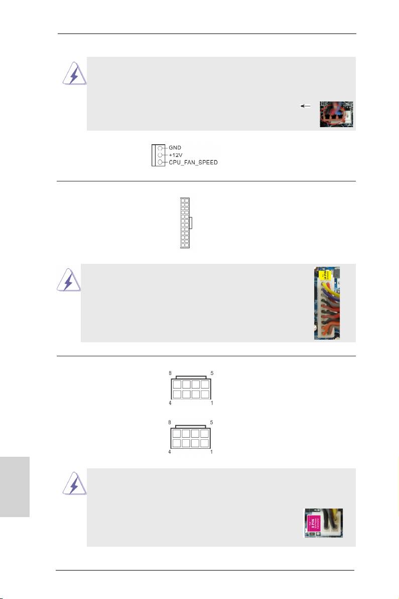
Though this motherboard provides 4-Pin CPU fan (Quiet Fan) support, the 3-Pin
CPU fan still can work successfully even without the fan speed control function.
If you plan to connect the 3-Pin CPU fan to the CPU fan connector on this
motherboard, please connect it to Pin 1-3.
Pin 1-3 Connected
3-Pin Fan Installation
(3-pin CPU_FAN2)
(see p.2, No. 8)
12
24
ATX Power Connector Please connect an ATX power
(24-pin ATXPWR1)
supply to this connector.
(see p.2, No. 11)
1
13
Though this motherboard provides 24-pin ATX power connector,
12
24
it can still work if you adopt a traditional 20-pin ATX power supply.
To use the 20-pin ATX power supply, please plug your
power supply along with Pin 1 and Pin 13.
20-Pin ATX Power Supply Installation
1
13
ATX 12V Power Connector Please connect ATX 12V power
(8-pin ATX12V1)
supplies to these connectors.
(see p.2, No. 5)
(8-pin ATX12V2)
(see p.2, No. 4)
English
Though this motherboard provides 8-pin ATX 12V power connectors, it can still
work if you adopt a traditional 4-pin ATX 12V power supply. To use the 4-pin ATX
power supply, please plug your power supply along with Pin 1 and Pin 5.
8 5
4-Pin ATX 12V Power Supply Installation
4 1
50
X79 Extreme11 Motherboard
SLI/XFIRE Power Connector It is not necessary to use this
(4-pin SLI/XFIRE_PWR1)
connector, but please connect it
(see p.2, No. 50)
with a hard disk power
SLI/XFIRE_PWR1
connecor when two graphics
cards are plugged to this
(4-pin SLI/XFIRE_PWR2)
motherboard.
(see p.2, No. 37)
SLI/XFIRE_PWR2
IEEE 1394 Header Besides one default IEEE 1394
(9-pin FRONT_1394)
port on the I/O panel, there
(see p.2, No. 40)
is one IEEE 1394 header
(FRONT_1394) on this
motherboard. This IEEE 1394
header can support one IEEE
1394 port.
HDMI_SPDIF Header HDMI_SPDIF header provides
(2-pin HDMI_SPDIF1)
SPDIF audio output to HDMI
(see p.2, No. 42)
VGA cards, allowing the system
to connect HDMI Digital TV/
projector/LCD devices. Please
connect the HDMI_SPDIF
connector of a HDMI VGA card
to this header.
English
51
X79 Extreme11 Motherboard
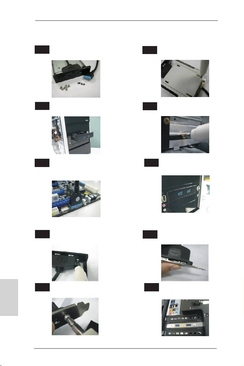
The Installation Guide of Front USB 3.0 Panel
Step 1
Prepare the bundled Front USB 3.0 Panel, four
Step 2
Screw the 2.5” HDD/SSD to the Front
HDD screws, and six chassis screws.
USB 3.0 Panel with four HDD screws.
Step 3
Intall the Front USB 3.0 Panel into the 2.5”
Step 4
Screw the Front USB 3.0 Panel to the
drive bay of the chassis.
drive bay with six chassis screws.
Step 5
Plug the Front USB 3.0 cable into the USB
Step 6
The Front USB 3.0 Panel is ready to use.
3.0 header (USB3_4_5 or USB3_6_7) on the
motherboard.
The Installation Guide of Rear USB 3.0 Bracket
Step 1
Unscrew the two screws from the Front USB 3.0
Step 2
Put the USB 3.0 cable and the rear
Panel.
USB 3.0 bracket together.
English
Step 3
Screw the two screws into the rear USB 3.0
Step 4
Put the rear USB 3.0 bracket into the
bracket.
chassis.
52
X79 Extreme11 Motherboard
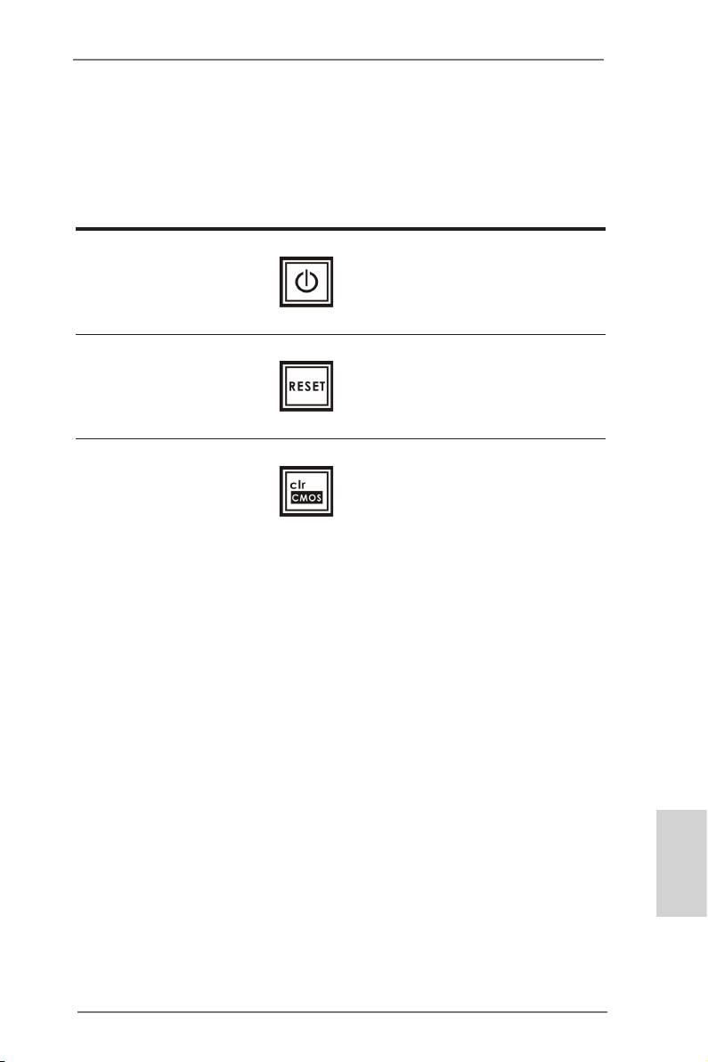
2.14 Smart Switches
The motherboard has three smart switches: power switch, reset switch and clear
CMOS switch, allowing users to quickly turn on/off or reset the system to clear the
CMOS values.
Power Switch Power Switch is a smart switch,
(PWRBTN)
allowing users to quickly turn
(see p.2, No. 30)
on/off the system.
Reset Switch Reset Switch is a smart switch,
(RSTBTN)
allowing users to quickly reset
(see p.2, No. 28)
the system.
Clear CMOS Switch Clear CMOS Switch is a smart
(CLRCBTN)
switch, allowing users to quickly
(see p.3, No. 17)
clear the CMOS values.
English
53
X79 Extreme11 Motherboard

2.15 Dr. Debug
Dr. Debug is used to provide code information, which makes troubleshooting even
easier. Please see the diagrams below for reading the Dr. Debug codes.
Status Code Description
0x00 Not used
0x01 Power on. Reset type detection (soft/hard)
0x02 AP initialization before microcode loading
0x03 North Bridge initialization before microcode loading
0x04 South Bridge initialization before microcode loading
0x05 OEM initialization before microcode loading
0x06 Microcode loading
0x07 AP initialization after microcode loading
0x08 North Bridge initialization after microcode loading
0x09 South Bridge initialization after microcode loading
0x0A OEM initialization after microcode loading
0x0B Cache initialization
0x0C – 0x0D Reserved for future AMI SEC error codes
0x0E Microcode not found
0x0F Microcode not loaded
0x10 PEI Core is started
0x11 Pre-memory CPU initialization is started
0x12 Pre-memory CPU initialization (CPU module specic)
0x13 Pre-memory CPU initialization (CPU module specic)
0x14 Pre-memory CPU initialization (CPU module specic)
0x15 Pre-memory North Bridge initialization is started
0x16 Pre-Memory North Bridge initialization (North Bridge module specic)
0x17 Pre-Memory North Bridge initialization (North Bridge module specic)
0x18 Pre-Memory North Bridge initialization (North Bridge module specic)
0x19 Pre-memory South Bridge initialization is started
0x1A Pre-memory South Bridge initialization (South Bridge module specic)
0x1B Pre-memory South Bridge initialization (South Bridge module specic)
0x1C Pre-memory South Bridge initialization (South Bridge module specic)
0x1D – 0x2A OEM pre-memory initialization codes
0x2B Memory initialization. Serial Presence Detect (SPD) data reading
0x2C Memory initialization. Memory presence detection
0x2D Memory initialization. Programming memory timing information
0x2E Memory initialization. Conguring memory
English
0x2F Memory initialization (other)
0x30 Reserved for ASL
0x31 Memory Installed
0x32 CPU post-memory initialization is started
0x33 CPU post-memory initialization. Cache initialization
0x34 CPU post-memory initialization. Application Processor(s) (AP) initialization
0x35 CPU post-memory initialization. Boot Strap Processor (BSP) selection
0x36 CPU post-memory initialization. System Management Mode (SMM)
initialization
54
X79 Extreme11 Motherboard

0x37 Post-Memory North Bridge initialization is started
0x38 Post-Memory North Bridge initialization (North Bridge module specic)
0x39 Post-Memory North Bridge initialization (North Bridge module specic)
0x3A Post-Memory North Bridge initialization (North Bridge module specic)
0x3B Post-Memory South Bridge initialization is started
0x3C Post-Memory South Bridge initialization (South Bridge module specic)
0x3D Post-Memory South Bridge initialization (South Bridge module specic)
0x3E Post-Memory South Bridge initialization (South Bridge module specic)
0x3F-0x4E OEM post memory initialization codes
0x4F DXE IPL is started
0x50 Memory initialization error. Invalid memory type or incompatible memory
speed
0x51 Memory initialization error. SPD reading has failed
0x52 Memory initialization error. Invalid memory size or memory modules do not
match
0x53 Memory initialization error. No usable memory detected
0x54 Unspecied memory initialization error
0x55 Memory not installed
0x56 Invalid CPU type or Speed
0x57 CPU mismatch
0x58 CPU self test failed or possible CPU cache error
0x59 CPU micro-code is not found or micro-code update is failed
0x5A Internal CPU error
0x5B reset PPI is not available
0x5C-0x5F Reserved for future AMI error codes
0xE0 S3 Resume is stared (S3 Resume PPI is called by the DXE IPL)
0xE1 S3 Boot Script execution
0xE2 Video repost
0xE3 OS S3 wake vector call
0xE4-0xE7 Reserved for future AMI progress codes
0xE8 S3 Resume Failed
0xE9 S3 Resume PPI not Found
0xEA S3 Resume Boot Script Error
0xEB S3 OS Wake Error
0xEC-0xEF Reserved for future AMI error codes
0xF0 Recovery condition triggered by rmware (Auto recovery)
0xF1 Recovery condition triggered by user (Forced recovery)
0xF2 Recovery process started
0xF3 Recovery rmware image is found
0xF4 Recovery rmware image is loaded
0xF5-0xF7 Reserved for future AMI progress codes
0xF8 Recovery PPI is not available
English
0xF9 Recovery capsule is not found
0xFA Invalid recovery capsule
0xFB – 0xFF Reserved for future AMI error codes
0x60 DXE Core is started
0x61 NVRAM initialization
55
X79 Extreme11 Motherboard

0x62 Installation of the South Bridge Runtime Services
0x63 CPU DXE initialization is started
0x64 CPU DXE initialization (CPU module specic)
0x65 CPU DXE initialization (CPU module specic)
0x66 CPU DXE initialization (CPU module specic)
0x67 CPU DXE initialization (CPU module specic)
0x68 PCI host bridge initialization
0x69 North Bridge DXE initialization is started
0x6A North Bridge DXE SMM initialization is started
0x6B North Bridge DXE initialization (North Bridge module specic)
0x6C North Bridge DXE initialization (North Bridge module specic)
0x6D North Bridge DXE initialization (North Bridge module specic)
0x6E North Bridge DXE initialization (North Bridge module specic)
0x6F North Bridge DXE initialization (North Bridge module specic)
0x70 South Bridge DXE initialization is started
0x71 South Bridge DXE SMM initialization is started
0x72 South Bridge devices initialization
0x73 South Bridge DXE Initialization (South Bridge module specic)
0x74 South Bridge DXE Initialization (South Bridge module specic)
0x75 South Bridge DXE Initialization (South Bridge module specic)
0x76 South Bridge DXE Initialization (South Bridge module specic)
0x77 South Bridge DXE Initialization (South Bridge module specic)
0x78 ACPI module initialization
0x79 CSM initialization
0x7A – 0x7F Reserved for future AMI DXE codes
0x80 – 0x8F OEM DXE initialization codes
0x90 Boot Device Selection (BDS) phase is started
0x91 Driver connecting is started
0x92 PCI Bus initialization is started
0x93 PCI Bus Hot Plug Controller Initialization
0x94 PCI Bus Enumeration
0x95 PCI Bus Request Resources
0x96 PCI Bus Assign Resources
0x97 Console Output devices connect
0x98 Console input devices connect
0x99 Super IO Initialization
0x9A USB initialization is started
0x9B USB Reset
English
0x9C USB Detect
0x9D USB Enable
0x9E – 0x9F Reserved for future AMI codes
0xA0 IDE initialization is started
0xA1 IDE Reset
0xA2 IDE Detect
0xA3 IDE Enable
0xA4 SCSI initialization is started
0xA5 SCSI Reset
56
X79 Extreme11 Motherboard

0xA6 SCSI Detect
0xA7 SCSI Enable
0xA8 Setup Verifying Password
0xA9 Start of Setup
0xAA Reserved for ASL
0xAB Setup Input Wait
0xAC Reserved for ASL
0xAD Ready To Boot event
0xAE Legacy Boot event
0xAF Exit Boot Services event
0xB0 Runtime Set Virtual Address MAP Begin
0xB1 Runtime Set Virtual Address MAP End
0xB2 Legacy Option ROM Initialization
0xB3 System Reset
0xB4 USB hot plug
0xB5 PCI bus hot plug
0xB6 Clean-up of NVRAM
0xB7 Conguration Reset (reset of NVRAM settings)
0xB8 – 0xBF Reserved for future AMI codes
0xC0 – 0xCF OEM BDS initialization codes
0xD0 CPU initialization error
0xD1 North Bridge initialization error
0xD2 South Bridge initialization error
0xD3 Some of the Architectural Protocols are not available
0xD4 PCI resource allocation error. Out of Resources
0xD5 No Space for Legacy Option ROM
0xD6 No Console Output Devices are found
0xD7 No Console Input Devices are found
0xD8 Invalid password
0xD9 Error loading Boot Option (LoadImage returned error)
0xDA Boot Option is failed (StartImage returned error)
0xDB Flash update is failed
0xDC Reset protocol is not available
English
57
X79 Extreme11 Motherboard

2.16 Driver Installation Guide
To install the drivers to your system, please insert the support CD to your optical
drive rst. Then, the drivers compatible to your system can be auto-detected and
listed on the support CD driver page. Please follow the order from top to bottom to
install those required drivers. Therefore, the drivers you install can work properly.
®
TM
TM
2.17 Installing Windows
7 / 7 64-bit / Vista
/ Vista
64-bit With
RAID Functions
®
TM
TM
If you want to install Windows
7 / 7 64-bit / Vista
/ Vista
64-bit on your SATA
/ SATA2 / SATA3 HDDs with RAID functions, please refer to the document at the
following path in the Support CD for detailed procedures:
..\ RAID Installation Guide
®
TM
TM
2.18 Installing Windows
7 / 7 64-bit / Vista
/ Vista
64-bit
Without RAID Functions
®
TM
TM
If you want to install Windows
7 / 7 64-bit / Vista
/ Vista
64-bit OS on your SATA
/ SATA2 / SATA3 HDDs without RAID functions, please follow the procedures below
according to the OS you install.
Using SATA / SATA2 / SATA3 HDDs with NCQ function
STEP 1: Set Up UEFI.
A. Enter UEFI SETUP UTILITY Advanced screen Storage Conguration.
B. Set the option “SATA Mode” to [AHCI]. (For SATA2_0 to SATA2_3, SATA3_0 and
SATA3_1 ports.)
Set the option “Marvell 9172 eSATA3_0_1 Operation Mode” to [AHCI].
®
TM
TM
STEP 2: Install Windows
7 / 7 64-bit / Vista
/ Vista
64-bit OS on your
system.
English
58
X79 Extreme11 Motherboard

Using SATA / SATA2 / SATA3 HDDs without NCQ function
STEP 1: Set Up UEFI.
A. Enter UEFI SETUP UTILITY Advanced screen Storage Conguration.
B. Set the option “SATA Mode” to [IDE]. (For SATA2_0 to SATA2_3, SATA3_0 and
SATA3_1 ports.)
Set the option “Marvell 9172 eSATA3_0_1 Operation Mode” to [IDE].
®
TM
TM
STEP 2: Install Windows
7 / 7 64-bit / Vista
/ Vista
64-bit OS on your
system.
2.19 Untied Overclocking Technology
This motherboard supports Untied Overclocking Technology, which means during
overclocking, BCLK enjoys better margin due to xed PCI / PCIE buses. Before you
enable Untied Overclocking function, please enter “Overclock Mode” option of UEFI
setup to set the selection from [Auto] to [Manual]. Therefore, BCLK is untied during
overclocking, but PCI / PCIE buses are in the xed mode so that BCLK can operate
under a more stable overclocking environment.
Please refer to the warning on page 8 for the possible overclocking risk
before you apply Untied Overclocking Technology.
English
59
X79 Extreme11 Motherboard

2.20 Teaming Function Operation Guide
Dual LAN with Teaming function enabled on this motherboard allows two single
connections to act as one single connection for twice the transmission bandwidth,
making data transmission more effective and improving the quality of transmission
of distant images. Fault tolerance on the dual LAN network prevents network
downtime by transferring the workload from a failed port to a working port.
The speed of transmission is subject to the actual network environment
or status even with Teaming enabled.
Before setting up Teaming function, please make sure if your Switch (or Router)
could support Teaming (IEEE 802.3ad Link Aggregation) function. Then, please
refer to following steps to set up Teaming function.
1. Install Teaming driver from the following path of motherboard Support CD:
32-bit: .. \Drivers\LAN\Broadcom\Teaming\IA32
64-bit: .. \Drivers\LAN\Broadcom\Teaming\x64
(This is a special driver for Teaming function only. If you don't want to use
Teaming, please install the LAN driver provided by our support CD link.)
2. From the Teams menu, select Create Team, or right-click one of the devices in
the “Unassigned Adapters” section and select Create a Team. This option is not
available if there are no devices listed in the “Unassigned Adapters” sections,
which means all adapters are already assigned to teams.
3. Click Expert Mode.
* If you want to always use Expert Mode to create a team, click Default to Expert
Mode on next start.
English
60
X79 Extreme11 Motherboard
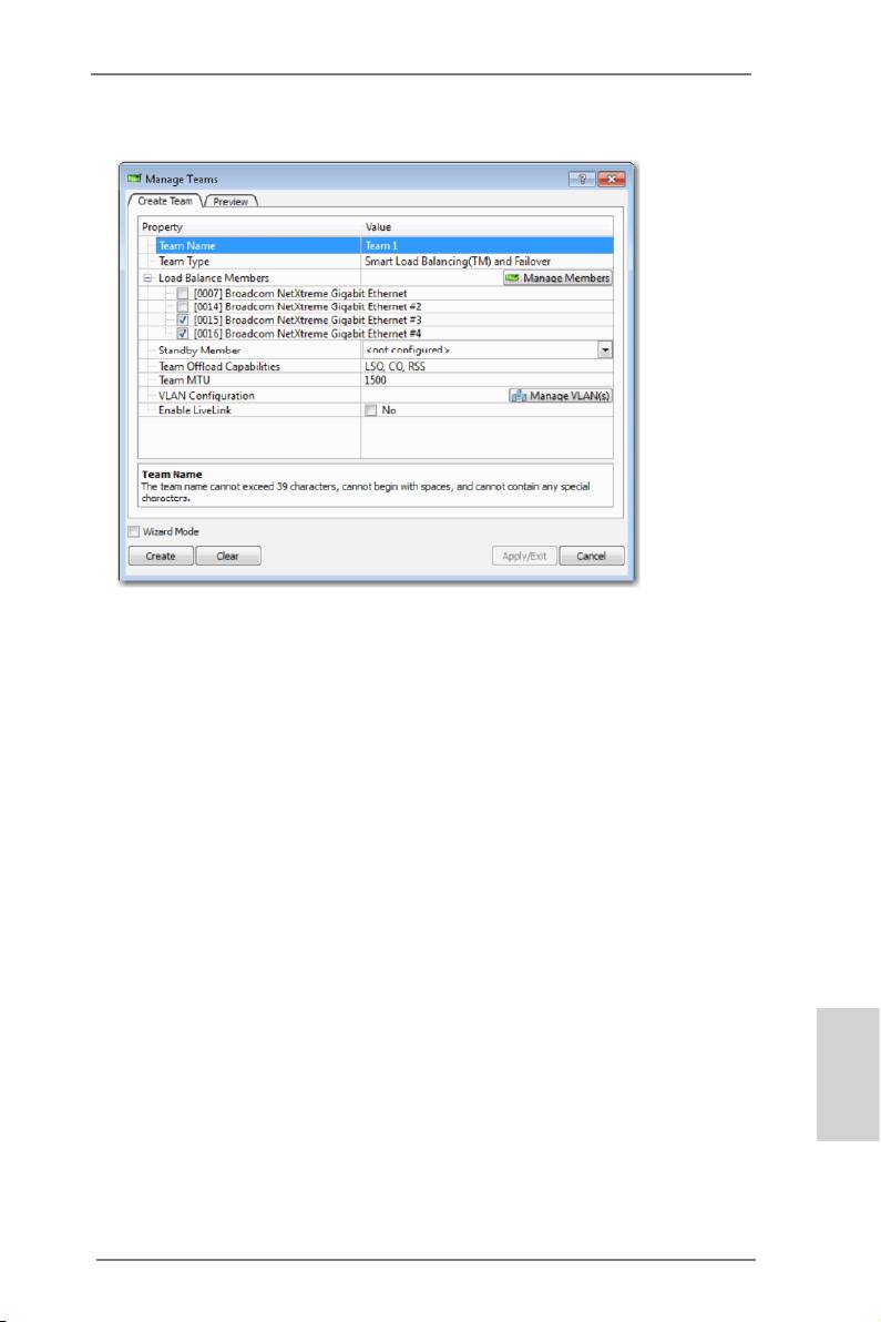
4. Click the Create Team tab.
* The Create Team tab appears only if there are teamable adapters available.
5. Click the Team Name eld to enter a team name.
6. Click the Team Type eld to select a team type.
7. Assign any available adapter or adapters to the team by selecting the adapter
from the Load Balance Members list. There must be at least one adapter
selected in the Load Balance Members list.
8. You can assign any other available adapter to be a standby member by selecting
it from the Standby Member list.
* There must be at least one Broadcom network adapter assigned to the team.
The Large Send Ofoad (LSO), Checksum Ofoad (CO), and RSS indicate if
the LSO, CO, and/or RSS properties are supported for the team. The LSO, CO,
and RSS properties are enabled for a team only when all of the members
support and are congured for the feature.
English
* Adding a network adapter to a team where its driver is disabled may negatively
affect the ofoading capabilities of the team. This may have an impact on the
team’s performance. Therefore, it is recommended that only driver-enabled
network adapters be added as members to a team.
61
X79 Extreme11 Motherboard

9. Type the value for Team MTU.
10. Click Create to save the team information.
11. Repeat steps 5. through 10. to dene additional teams. As teams are dened,
they can be selected from the team list, but they have not yet been created.
Click the Preview tab to view the team structure before applying the changes.
12. Click Apply/Exit to create all the teams you have dened and exit the Manage
Teams window.
13. Click Yes when the message is displayed indicating that the network connection
will be temporarily interrupted.
* The team name cannot exceed 39 characters, cannot begin with spaces, and
cannot contain any of the following characters: & \ / : * ? < > |
* Team names must be unique. If you attempt to use a team name more than
once, an error message is displayed indicating that the name already exists.
* The maximum number of team members is 8.
* When team conguration has been correctly performed, a virtual team adapter
driver is created for each congured team.
* If you disable a virtual team and later want to reenable it, you must rst disable
and reenable all team members before you reenable the virtual team.
* When you create Generic Trunking and Link Aggregation teams, you cannot
designate a standby member. Standby members work only with Smart Load
Balancing and Failover and SLB (Auto-Fallback Disable) types of teams.
* For an SLB (Auto-Fallback Disable) team, to restore trafc to the load balance
members from the standby member, click the Fallback button on the Team
English
Properties tab.
* When conguring an SLB team, although connecting team members to a hub
is supported for testing, it is recommended to connect team members to a
switch.
62
X79 Extreme11 Motherboard

* Not all network adapters made by others are supported or fully certied for
teaming.
14. Congure the team IP address.
a. From Control Panel, double-click Network Connections.
b. Right-click the name of the team to be congured, and then click Properties.
c. On the General tab, click Internet Protocol (TCP/IP), and then click
Properties.
d. Congure the IP address and any other necessary TCP/IP conguration for
the team, and then click OK when nished.
English
63
X79 Extreme11 Motherboard
Оглавление
- 1. Introduction
- 2. Installation
- 3. BIOS Information
- 1. Einführung
- 2. BIOS-Information
- 1. Introduction
- 2. Informations sur le BIOS
- 1. Introduzione
- 2. Informazioni sul BIOS
- 1. Introducción
- 2. BIOS Información
- 1. Введение
- 2. Информация о BIOS
- 1. Giriş
- 2. BIOS Bilgileri
- 1. 제품소개
- 2. 시스템 바이오스 정보
- 1. 主板簡介
- 2. BIOS 信息
- 1. 主機板簡介
- 2. BIOS 訊息
- 1. Penjelasan
- Installing OS on a HDD Larger Than 2TB
