ASRock Fatal1ty Z87 Professional: Chapter 2 Installation
Chapter 2 Installation: ASRock Fatal1ty Z87 Professional

Chapter 2 Installation
is is an ATX form factor motherboard. Before you install the motherboard, study
the conguration of your chassis to ensure that the motherboard ts into it.
Pre-installation Precautions
Take note of the following precautions before you install motherboard components
or change any motherboard settings.
•
Make sure to unplug the power cord before installing or removing the motherboard.
Failure to do so may cause physical injuries to you and damages to motherboard
components.
•
In order to avoid damage from static electricity to the motherboard’s components,
NEVER place your motherboard directly on a carpet. Also remember to use a grounded
wrist strap or touch a safety grounded object before you handle the components.
•
Hold components by the edges and do not touch the ICs.
•
Whenever you uninstall any components, place them on a grounded anti-static pad or
in the bag that comes with the components.
•
When placing screws to secure the motherboard to the chassis, please do not over-
tighten the screws! Doing so may damage the motherboard.
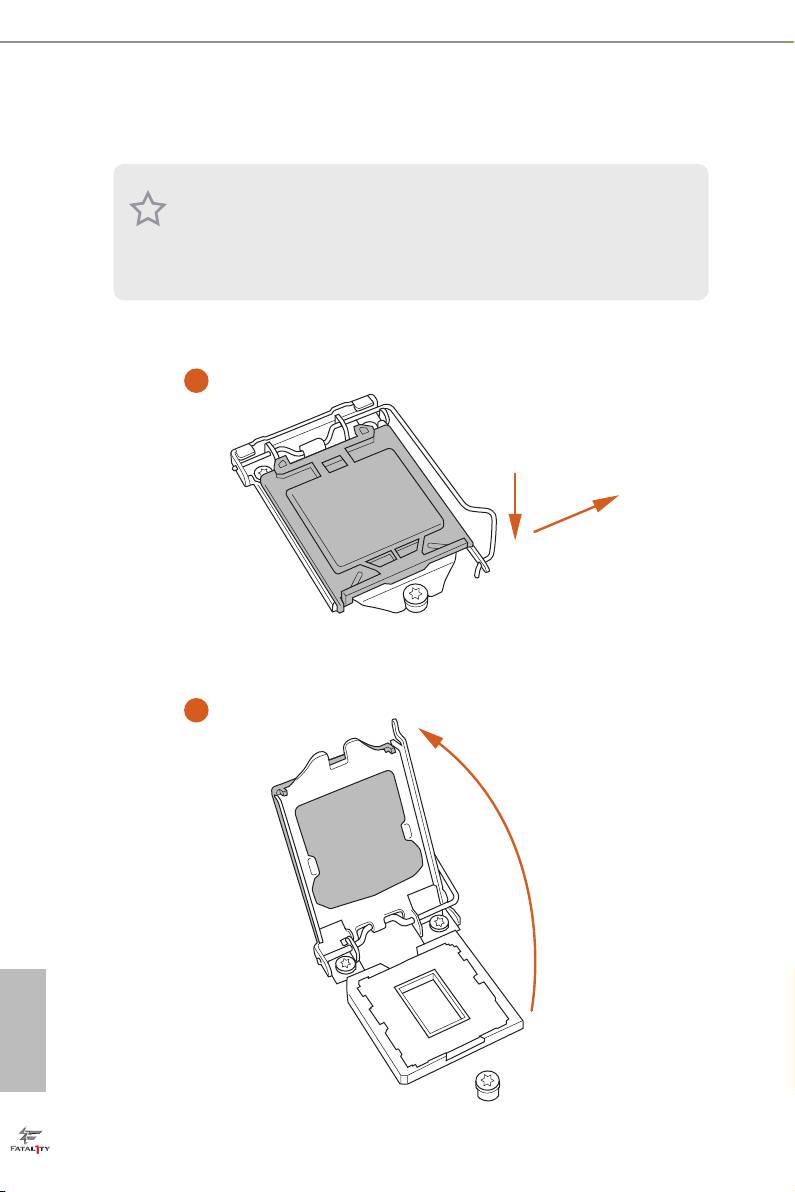
2.1 Installing the CPU
1. Before you insert the 1150-Pin CPU into the socket, please check if the PnP cap is on
the socket, if the CPU surface is unclean, or if there are any bent pins in the socket.
Do not force to insert the CPU into the socket if above situation is found. Otherwise,
the CPU will be seriously damaged.
2. Unplug all power cables before installing the CPU.
1
A
B
2
English
16
Fatal1ty Z87 Professional Series
3
4
5
English
17

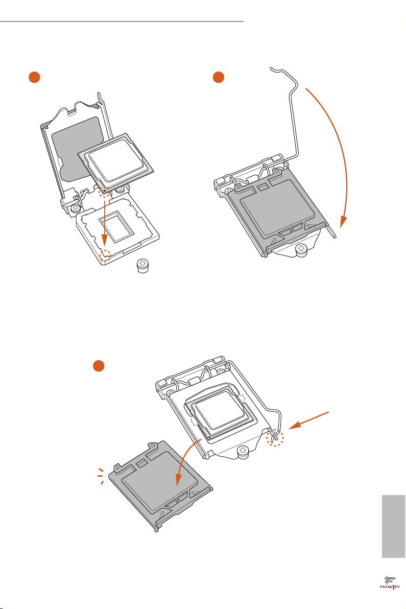
Please save and replace the cover if the processor is removed. e cover must be placed
if you wish to return the motherboard for aer service.
English
18

Fatal1ty Z87 Professional Series
2.2 Installing the CPU Fan and Heatsink
1 2
FAN
CPU_
English
19
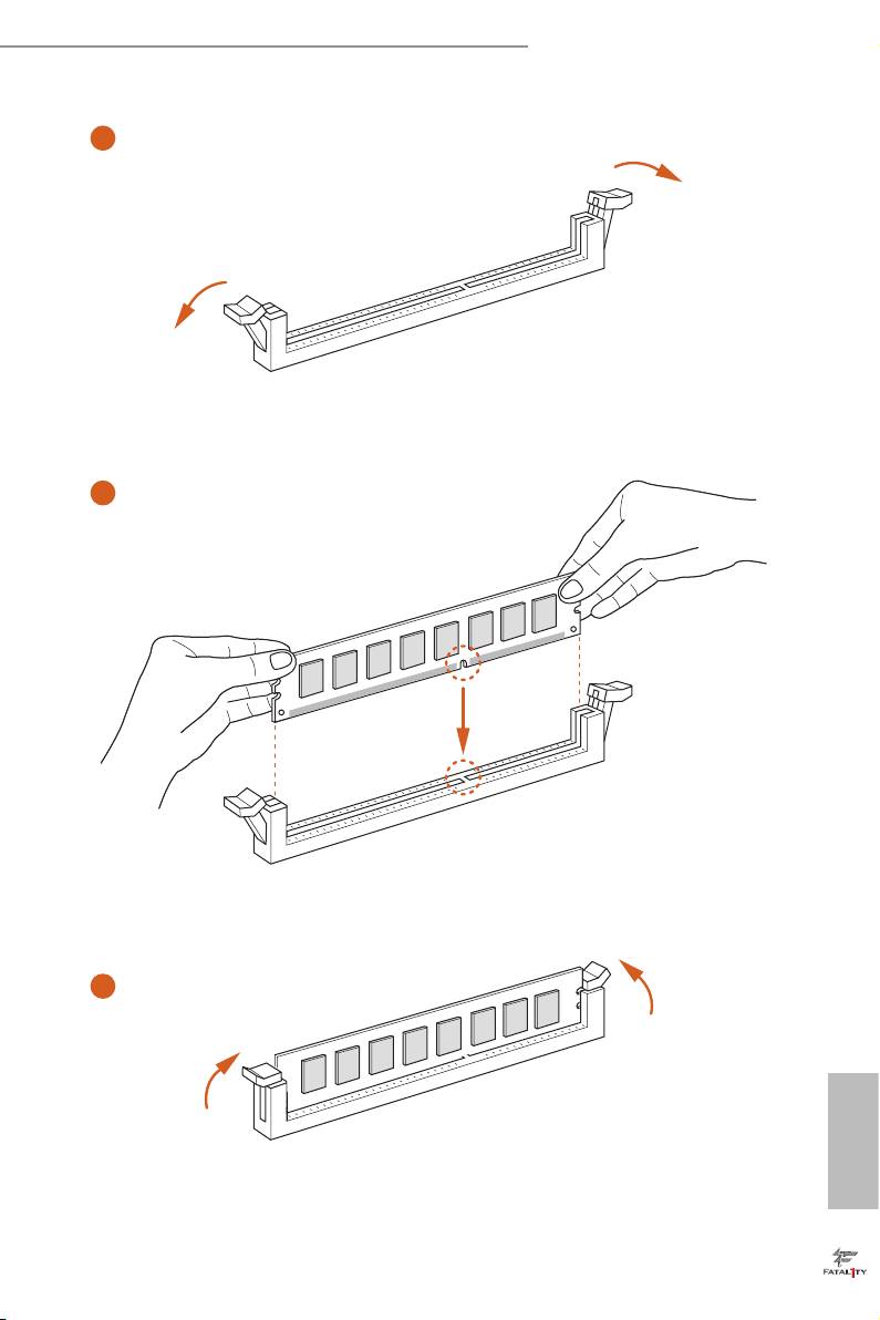
2.3 Installing Memory Modules (DIMM)
is motherboard provides four 240-pin DDR3 (Double Data Rate 3) DIMM slots,
and supports Dual Channel Memory Technology.
1. For dual channel conguration, you always need to install identical (the same
brand, speed, size and chip-type) DDR3 DIMM pairs.
2. It is unable to activate Dual Channel Memory Technology with only one or three
memory module installed.
3. It is not allowed to install a DDR or DDR2 memory module into a DDR3 slot;
otherwise, this motherboard and DIMM may be damaged.
Dual Channel Memory Conguration
Priority DDR3_A1 DDR3_A2 DDR3_B1 DDR3_B2
1 Populated Populated
2 Populated Populated
3 Populated Populated Populated Populated
e DIMM only ts in one correct orientation. It will cause permanent damage to
the motherboard and the DIMM if you force the DIMM into the slot at incorrect
orientation.
English
20
Fatal1ty Z87 Professional Series
1
2
3
English
21
2.4 Expansion Slots (PCI and PCI Express Slots)
ere are 2 PCI slots and 5 PCI Express slots on the motherboard.
Before installing an expansion card, please make sure that the power supply is
switched o or the power cord is unplugged. Please read the documentation of the
expansion card and make necessary hardware settings for the card before you start
the installation.
PCI slot:
e PCI1 and PCI2 slots are used to install expansion cards that have 32-bit PCI
interface.
PCIe slots:
PCIE1 (PCIe 2.0 x1 slots) is used for PCI Express x1 lane width cards.
PCIE2 (PCIe 3.0 x16 slot) is used for PCI Express x16 lane width graphics cards.
PCIE3 (PCIe 3.0 x16 slot) is used for PCI Express x8 lane width graphics cards.
PCIE4 (PCIe 3.0 x16 slot) is used for PCI Express x4 lane width graphics cards
MINI_PCIE1 (mini-PCIe slot) is used for WiFi module.
PCIe Slot Congurations
PCIE2 PCIE3 PCIE4
Single Graphics Card x16 N/A N/A
Two Graphics Cards in
x8 x8 N/A
TM
TM
CrossFireX
or SLI
Mode
ree Graphics Cards in
x8 x4 x4
TM
3-Way CrossFireX
Mode
For a better thermal environment, please connect a chassis fan to the motherboard’s
English
chassis fan connector (CHA_FAN1, CHA_FAN2 or CHA_FAN3) when using mul-
tiple graphics cards.
22
Fatal1ty Z87 Professional Series
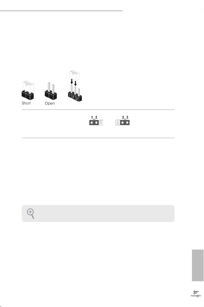
2.5 Jumpers Setup
e illustration shows how jumpers are setup. When the jumper cap is placed on
the pins, the jumper is “Short”. If no jumper cap is placed on the pins, the jumper
is “Open”. e illustration shows a 3-pin jumper whose pin1 and pin2 are “Short”
when a jumper cap is placed on these 2 pins.
Clear CMOS Jumper
(CLRCMOS1)
Clear CMOSDefault
(see p.1, No. 21)
CLRCMOS1 allows you to clear the data in CMOS. To clear and reset the system
parameters to default setup, please turn o the computer and unplug the power
cord from the power supply. Aer waiting for 15 seconds, use a jumper cap to
short pin2 and pin3 on CLRCMOS1 for 5 seconds. However, please do not clear
the CMOS right aer you update the BIOS. If you need to clear the CMOS when
you just nish updating the BIOS, you must boot up the system rst, and then shut
it down before you do the clear-CMOS action. Please be noted that the password,
date, time, and user default prole will be cleared only if the CMOS battery is
removed.
e Clear CMOS Switch has the same function as the Clear CMOS jumper.
English
23
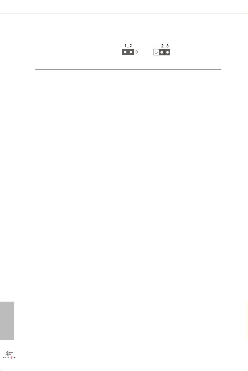
BIOS Selection Jumper
(BIOS_SEL1)
(see p.1, No. 20)
Default
Backup BIOS
(Main BIOS)
is motherboard has two BIOS onboard, a main BIOS (BIOS_A) and a backup
BIOS (BIOS_B), which enhances protection for the safety and stability of your
system. Normally, the system works on the main BIOS. However, if the main BIOS
is corrupted or damaged, please use a jumper cap to short pin2 and pin3, then the
backup BIOS will take over on the next system boot. Aer that, short pin1 and
pin2 again, then use “Secure Backup UEFI“ in BIOS setup utility to copy the BIOS
le to the main BIOS to ensure normal system operation. For the sake of system
safety, users cannot update the backup BIOS manually. Users may refer to the
BIOS LED (BIOS_A_LED or BIOS_B_LED) to identify which BIOS is activated
currently.
English
24
Fatal1ty Z87 Professional Series
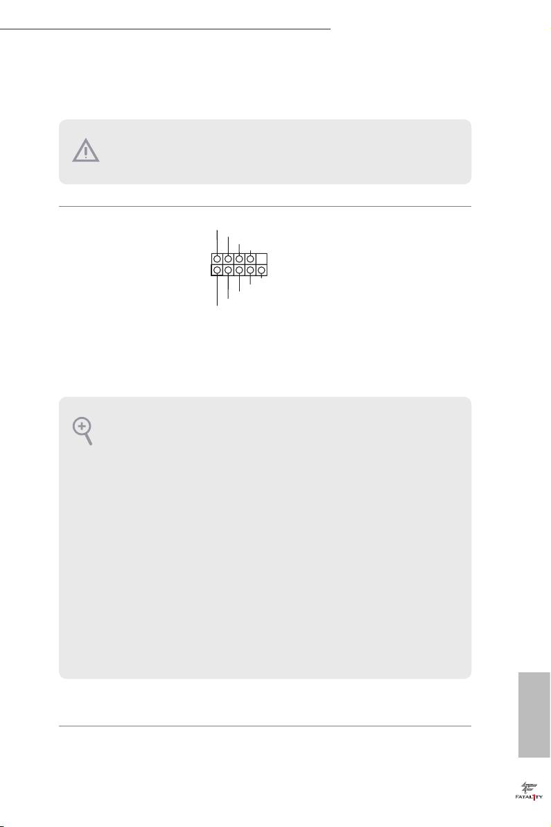
2.6 Onboard Headers and Connectors
Onboard headers and connectors are NOT jumpers. Do NOT place jumper caps over
these headers and connectors. Placing jumper caps over the headers and connectors
will cause permanent damage to the motherboard.
P LED+
System Panel Header
Connect the power
P LED-
P WRBTN#
(9-pin PANEL1)
GND
switch, reset switch and
(see p.1, No. 17)
system status indicator on
1
GND
the chassis to this header
R ESET#
GND
according to the pin
H DLED-
H DLED+
assignments below. Note
the positive and negative
pins before connecting
the cables.
PWRBTN (Power Switch):
Connect to the power switch on the chassis front panel. You may congure the way to
turn o your system using the power switch.
RESET (Reset Switch):
Connect to the reset switch on the chassis front panel. Press the reset switch to restart
the computer if the computer freezes and fails to perform a normal restart.
PLED (System Power LED):
Connect to the power status indicator on the chassis front panel. e LED is on when
the system is operating. e LED keeps blinking when the system is in S1/S3 sleep state.
e LED is o when the system is in S4 sleep state or powered o (S5).
HDLED (Hard Drive Activity LED):
Connect to the hard drive activity LED on the chassis front panel. e LED is on when
the hard drive is reading or writing data.
e front panel design may dier by chassis. A front panel module mainly consists
of power switch, reset switch, power LED, hard drive activity LED, speaker and etc.
When connecting your chassis front panel module to this header, make sure the wire
assignments and the pin assignments are matched correctly.
English
25
Power LED Header
Please connect the chassis
1
PLED-
(3-pin PLED1)
power LED to this header
PLED+
PLED+
(see p.1, No. 18)
to
indicate the system’s
power status.
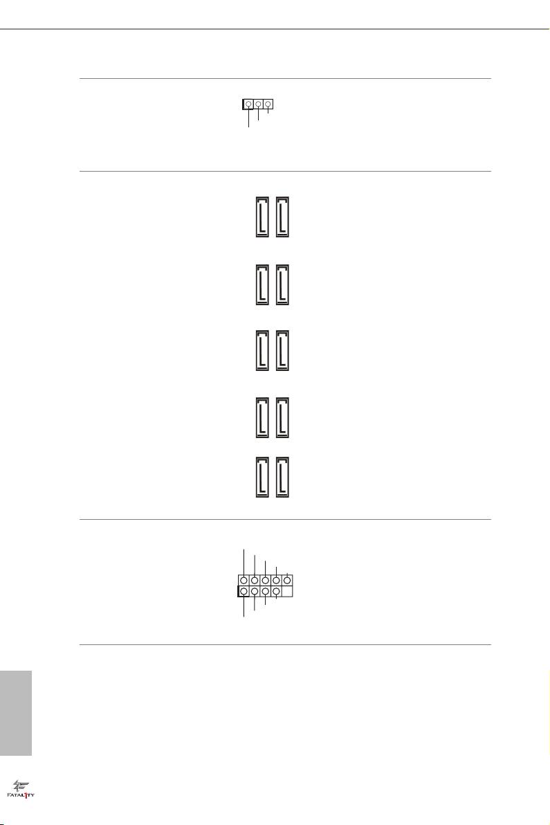
Serial ATA3 Connectors
ese ten SATA3
(SATA3_0_1:
connectors support SATA
see p.1, No. 11)
data cables for internal
(SATA3_2_3:
SATA3_A3_A4SATA3_A1_A2
storage devices with up
see p.1, No. 12)
to 6.0 Gb/s data transfer
(SATA3_4_5:
rate. If the eSATA port
see p.1, No. 13)
on the rear I/O has been
(SATA3_A1_A2:
connected, the internal
see p.1, No. 10)
SATA3_A4 will not
(SATA3_A3_A4:
function.
see p.1, No. 9)
To minimize the boot
SATA3_0_1SATA3_4_5 SATA3_2_3
time, use Intel® Z87 SATA
ports (SATA3_0) for your
bootable devices.
USB 2.0 Headers
Besides four USB 2.0 ports
USB_PWR
P-
(9-pin USB4_5)
P+
on the I/O panel, there
GND
DUMMY
(see p.1, No. 22)
are two headers on this
(9-pin USB6_7)
motherboard. Each USB
1
GND
(see p.1, No. 23)
P+
2.0 header can support
P-
USB_PWR
two ports.
English
26
Fatal1ty Z87 Professional Series
VbusVbus
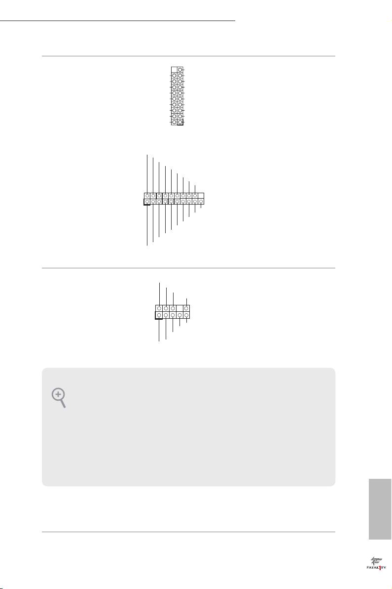
USB 3.0 Headers
Besides four USB 3.0 ports
Vbus
IntA_ PB_S SR X -
IntA_ PA_S SR X -
IntA_ PB_S SR X +
(19-pin USB3_4_5)
on the I/O panel, there
IntA_ PA_S SR X +
GND
GND
IntA_ PB_S ST X -
(see p.1, No. 8)
are two headers on this
IntA_ PA_S ST X -
IntA_ PB_S ST X +
IntA_ PA_S ST X +
GND
motherboard. Each USB
GND
IntA_ PB_D -
IntA_ PA_D -
IntA_ PB_D +
3.0 header can support
IntA_ PA_D +
Dummy
1
two ports.
In tA_P _D+
(19-pin USB3_6_7)
In tA_P _D-
GN D
In tA_P _SST X+
(see p.1, No. 24)
In tA_P _SST X-
GN D
In tA_P _SSR X+
In tA_P _SSR X-
Vb us
1
Vb us
In tA_P _SSR X-
In tA_P _SSR X+
GN D
In tA_P _SST X-
In tA_P _SST X+
GN D
In tA_P _D-
In tA_P _D+
ID
GN D
Front Panel Audio Header
is header is for
P RESENCE#
M IC_RET
(9-pin HD_AUDIO1)
OUT_RET
connecting audio devices
(see p.1, No. 29)
to the front audio panel.
1
O UT2_L
J _SENSE
O UT2_R
M IC2_R
M IC2_L
1. High Denition Audio supports Jack Sensing, but the panel wire on the chassis must
support HDA to function correctly. Please follow the instructions in our manual and
chassis manual to install your system.
2. If you use an AC’97 audio panel, please install it to the front panel audio header by
the steps below:
A. Connect Mic_IN (MIC) to MIC2_L.
B. Connect Audio_R (RIN) to OUT2_R and Audio_L (LIN) to OUT2_L.
C. Connect Ground (GND) to Ground (GND).
D. MIC_RET and OUT_RET are for the HD audio panel only. You don’t need to
connect them for the AC’97 audio panel.
English
27
Chassis Speaker Header
Please connect the chassis
(4-pin SPEAKER1)
speaker to this header.
(see p.1, No. 16)
SPDIF Out Connector
Please connect the
(2-pin SPDIF_OUT1)
SPDIF_OUT connector of
(see p.1, No. 28)
a HDMI VGA card to this
header with a cable.
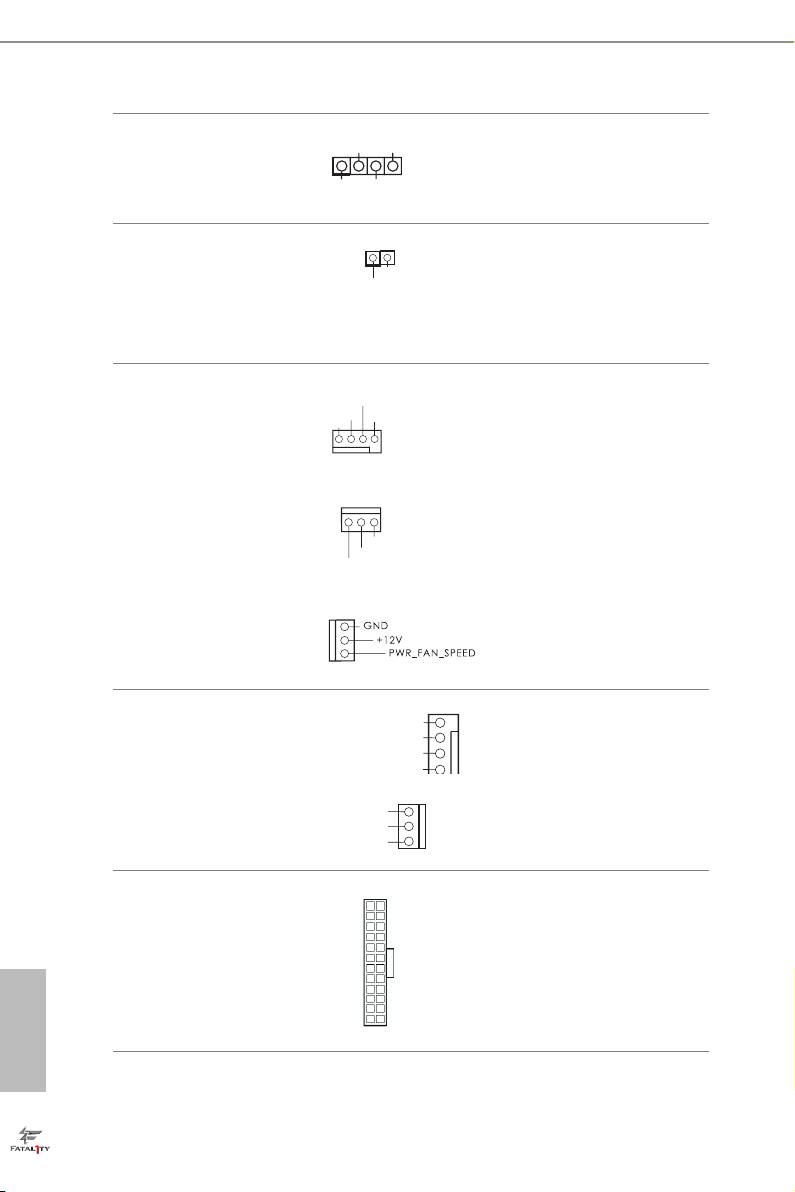
Chassis and Power Fan
Please connect fan cables
Connectors
to the fan connectors and
(4-pin CHA_FAN1)
match the black wire to
(see p.1, No. 19)
the ground pin.
(3-pin CHA_FAN2)
(see p.1, No. 31)
(3-pin CHA_FAN3)
(see p.1, No. 30)
(3-pin PWR_FAN1)
(see p.1, No. 1)
CPU Fan Connectors
is motherboard pro-
(4-pin CPU_FAN1)
vides a 4-Pin CPU fan
(see p.1, No. 3)
(Quiet Fan) connector.
If you plan to connect a
(3-pin CPU_FAN2)
3-Pin CPU fan, please
(see p.1, No. 4)
connect it to Pin 1-3.
ATX Power Connector
is motherboard pro-
(24-pin ATXPWR1)
vides a 24-pin ATX power
(see p.1, No. 7)
connector. To use a 20-pin
ATX power supply, please
English
plug it along Pin 1 and Pin
13.
28
GND
+12V
FAN_SPEED
FAN_SPEED
+
12V
GND
GND
DUMMY
SPEAKER
1
+5V
DUMMY
1
GN D
SP DIFOUT
CH A _FAN_SPEED
+1 2 V
FA N _SPEED_CONTROL
GN D
FAN_SPEED_CONTROL
CPU_FAN_SPEED
+12V
12
24
1
13
Fatal1ty Z87 Professional Series
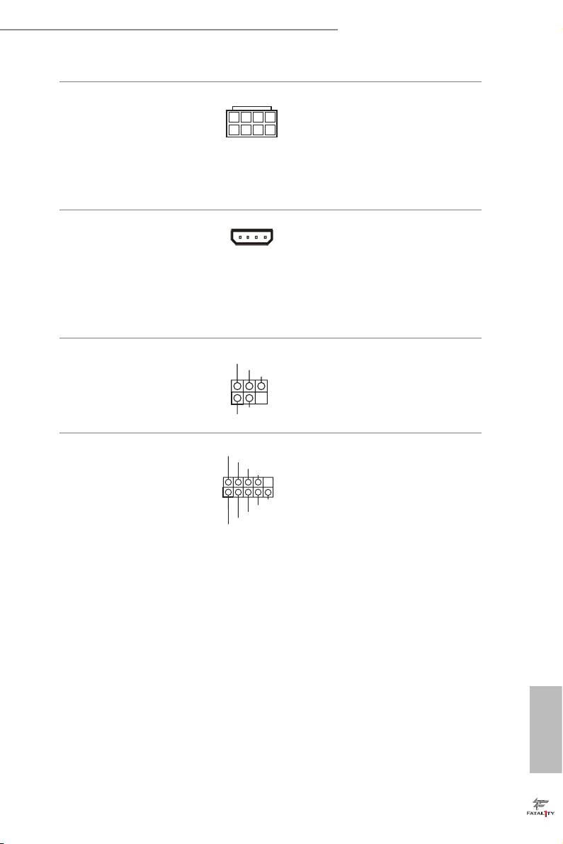
ATX 12V Power
8 5
is motherboard pro-
Connector
vides an 8-pin ATX 12V
(8-pin ATX12V1)
power connector. To use a
4 1
(see p.1, No. 2)
4-pin ATX power supply,
please plug it along Pin 1
and Pin 5.
SLI/XFIRE Power
Please connect this
Connector
connector with a hard
(4-pin SLI/XFIRE_
disk power connector
PWR1)
when two graphics cards
(see p.1, No. 26)
are installed on this
motherboard.
Infrared Module Header
IRTX
is header supports an optional
+5VSB
DUMMY
(5-pin IR1)
wireless transmitting and
(see p.1, No. 27)
receiving infrared module.
1
GND
IRRX
RRXD1
Serial Port Header
is COM1 header
DDTR#1
DDSR#1
(9-pin COM1)
CCTS#1
supports a serial port
(see p.1, No. 25)
module.
1
RRI#1
RRTS#1
GND
TTXD1
DDCD#1
English
29
2.7 Smart Switches
e motherboard has three smart switches: Power Switch, Reset Switch and Clear
CMOS Switch, allowing users to quickly turn on/o the system, reset the system or
clear the CMOS values.
Power Switch
Power Switch allows users
Power
(PWRBTN)
to quickly turn on/o the
(see p.1, No. 14)
system.
Reset Switch
Reset Switch allows
(RSTBTN)
Reset
users to quickly reset the
(see p.1, No. 15)
system.
Clear CMOS Switch
Clear CMOS Switch
(CLRCBTN)
allows users to quickly
(see p.3, No. 18)
clear the CMOS values.
is function is operational only when you power o your computer and unplug the
power supply.
English
30

Fatal1ty Z87 Professional Series
2.8 Dr. Debug
Dr. Debug is used to provide code information, which makes troubleshooting even
easier. Please see the diagrams below for reading the Dr. Debug codes.
Code Description
00 Please check if the CPU is installed correctly and then clear
CMOS.
0d Problem related to memory, VGA card or other devices.
Please clear CMOS, re-install the memory and VGA card,
and remove other USB, PCI devices.
01 - 54
Problem related to memory. Please re-install the CPU and
(except 0d),
memory then clear CMOS. If the problem still exists, please
5A- 60
install only one memory module or try using other memory
modules.
55 e Memory could not be detected. Please re-install the
memory and CPU. If the problem still exists, please install
only one memory module or try using other memory
modules.
61 - 91 Chipset initialization error. Please press reset or clear
CMOS.
92 - 99 Problem related to PCI-E devices. Please re-install PCI-E
devices or try installing them in other slots. If the problem
still exists, please remove all PCI-E devices or try using
another VGA card.
A0 - A7 Problem related to IDE or SATA devices. Please re-install
IDE and SATA devices. If the problem still exists, please
clear CMOS and try removing all SATA devices.
b0 Problem related to memory. Please re-install the CPU and
memory. If the problem still exists, please install only one
memory module or try using other memory modules.
English
31

b4 Problem related to USB devices. Please try removing all
USB devices.
b7 Problem related to memory. Please re-install the CPU and
memory then clear CMOS. If the problem still exists, please
install only one memory module or try using other memory
modules.
d6 e VGA could not be recognized. Please clear CMOS and
try re-installing the VGA card. If the problem still exists,
please try installing the VGA card in other slots or use other
VGA cards.
d7 e Keyboard and mouse could not be recognized. Please
try re-installing the keyboard and mouse.
d8 Invalid Password.
FF Please check if the CPU is installed correctly and then clear
CMOS.
English
32
