ASRock 980DE3__U3S3: 2. Installation
2. Installation: ASRock 980DE3__U3S3
2. Installation
This is an ATX form factor motherboard. Before you install the motherboard, study
the conguration of your chassis to ensure that the motherboard ts into it.
Pre-installation Precautions
Take note of the following precautions before you install motherboard
components or change any motherboard settings.
Before you install or remove any component, ensure that the
power is switched off or the power cord is detached from the
power supply. Failure to do so may cause severe damage to
the motherboard, peripherals, and/or components.
1. Unplug the power cord from the wall socket before touching any
component.
2. To avoid damaging the motherboard components due to static elec-
tricity, NEVER place your motherboard directly on the carpet or the
like. Also remember to use a grounded wrist strap or touch a safety
grounded object before you handle components.
3. Hold components by the edges and do not touch the ICs.
4. Whenever you uninstall any component, place it on a grounded
anti-static pad or in the bag that comes with the component.
5. When placing screws into the screw holes to secure the mother-
board to the chassis, please do not over-tighten the screws! Doing
so may damage the motherboard.
English
11
ASRock 980DE3/U3S3 Motherboard
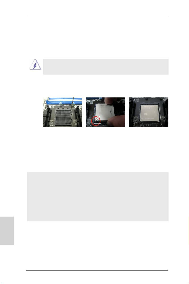
2.1 CPU Installation
o
Step 1. Unlock the socket by lifting the lever up to a 90
angle.
Step 2. Position the CPU directly above the socket such that the CPU corner with
the golden triangle matches the socket corner with a small triangle.
Step 3. Carefully insert the CPU into the socket until it ts in place.
The CPU ts only in one correct orientation. DO NOT force the CPU
into the socket to avoid bending of the pins.
Step 4. When the CPU is in place, press it rmly on the socket while you push
down the socket lever to secure the CPU. The lever clicks on the side tab
to indicate that it is locked.
Lever 90° Up
CPU Golden Triangle
Socker Corner
Small Triangle
STEP 1:
STEP 2 / STEP 3:
STEP 4:
Lift Up The Socket Lever
Match The CPU Golden Triangle
Push Down And Lock
To The Socket Corner Small
The Socket Lever
Triangle
2.2 Installation of CPU Fan and Heatsink
After you install the CPU into this motherboard, it is necessary to install a
larger heatsink and cooling fan to dissipate heat. You also need to spray
thermal grease between the CPU and the heatsink to improve heat dis-
sipation. Make sure that the CPU and the heatsink are securely fastened
and in good contact with each other. Then connect the CPU fan to the
CPU FAN connector (CPU_FAN1, see Page 2, No. 3). For proper instal-
lation, please kindly refer to the instruction manuals of the CPU fan and
the heatsink.
English
12
ASRock 980DE3/U3S3 Motherboard
2.3 Installation of Memory Modules (DIMM)
This motherboard provides four 240-pin DDR3 (Double Data Rate 3) DIMM slots,
and supports Dual Channel Memory Technology. For dual channel conguration,
you always need to install identical (the same brand, speed, size and chip-type)
DDR3 DIMM pair in the slots. In other words, you have to install identical DDR3
DIMM pair in Dual Channel (DDR3_A1 and DDR3_B1; Black slots; see p.2 No.6)
or identical DDR3 DIMM pair in Dual Channel (DDR3_A2 and DDR3_B2; Black
slots; see p.2 No.7), so that Dual Channel Memory Technology can be activated.
This motherboard also allows you to install four DDR3 DIMMs for dual channel
conguration, and please install identical DDR3 DIMMs in all four slots. You may
refer to the Dual Channel Memory Conguration Table below.
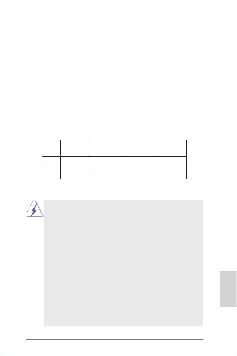
Dual Channel Memory Congurations
DDR3_A1 DDR3_A2 DDR3_B1 DDR3_B2
(Black Slot) (Black Slot) (Black Slot) (Black Slot)
(1) Populated - Populated -
(2) - Populated - Populated
(3)* Populated Populated Populated Populated
*
For the conguration (3), please install identical DDR3 DIMMs in all four
slots.
1. Please install the memory module into the slots DDR3_A2 and
DDR3_B2 for the rst priority.
2. If you want to install two memory modules, for optimal compatibility
and reliability, it is recommended to install them either in the set of
slots DDR3_A1 and DDR3_B1, or in the set of slots DDR3_A2 and
DDR3_B2.
3. If only one memory module or three memory modules are installed
in the DDR3 DIMM slots on this motherboard, it is unable to activate
the Dual Channel Memory Technology.
4. If a pair of memory modules is NOT installed in the same Dual
Channel, for example, installing a pair of memory modules in
DDR3_A1 and DDR3_A2, it is unable to activate the Dual Channel
Memory Technology .
5. It is not allowed to install a DDR or DDR2 memory module into
DDR3 slot; otherwise, this motherboard and DIMM may be dam-
English
aged.
6. If you adopt DDR3 1866/1600 memory modules on this mother-
board, it is recommended to install them on DDR3_A2 and DDR3_
B2 slots.
13
ASRock 980DE3/U3S3 Motherboard
Installing a DIMM
Please make sure to disconnect power supply before adding or
removing DIMMs or the system components.
Step 1. Unlock a DIMM slot by pressing the retaining clips outward.
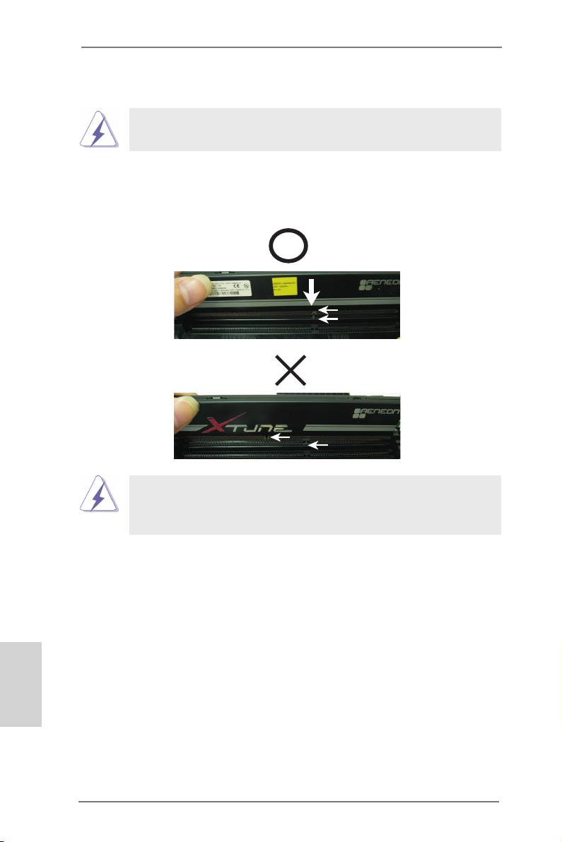
Step 2. Align a DIMM on the slot such that the notch on the DIMM matches the
break on the slot.
notch
break
notch
break
The DIMM only ts in one correct orientation. It will cause permanent
damage to the motherboard and the DIMM if you force the DIMM into
the slot at incorrect orientation.
Step 3. Firmly insert the DIMM into the slot until the retaining clips at both ends
fully snap back in place and the DIMM is properly seated.
English
14
ASRock 980DE3/U3S3 Motherboard

2.4 Expansion Slots (PCI and PCI Express Slots)
There are 2 PCI slots and 4 PCI Express slots on this motherboard.
PCI Slots: PCI slots are used to install expansion cards that have the 32-bit PCI
interface.
PCIE Slots:
PCIE1 / PCIE2 / PCIE4 (PCIE x1 slot; Black) is used for PCI Express
cards with x1 lane width cards, such as Gigabit LAN card and SATA2
card.
PCIE3 (PCIE x16 slot; Black) is used for PCI Express x16 lane width
graphics cards.
Installing an expansion card
Step 1. Before installing the expansion card, please make sure that the power
supply is switched off or the power cord is unplugged. Please read the
documentation of the expansion card and make necessary hardware
settings for the card before you start the installation.
Step 2. Remove the system unit cover (if your motherboard is already installed
in a chassis).
Step 3. Remove the bracket facing the slot that you intend to use. Keep the
screws for later use.
Step 4. Align the card connector with the slot and press rmly until the card is
completely seated on the slot.
Step 5. Fasten the card to the chassis with screws.
Step 6. Replace the system cover.
English
15
ASRock 980DE3/U3S3 Motherboard
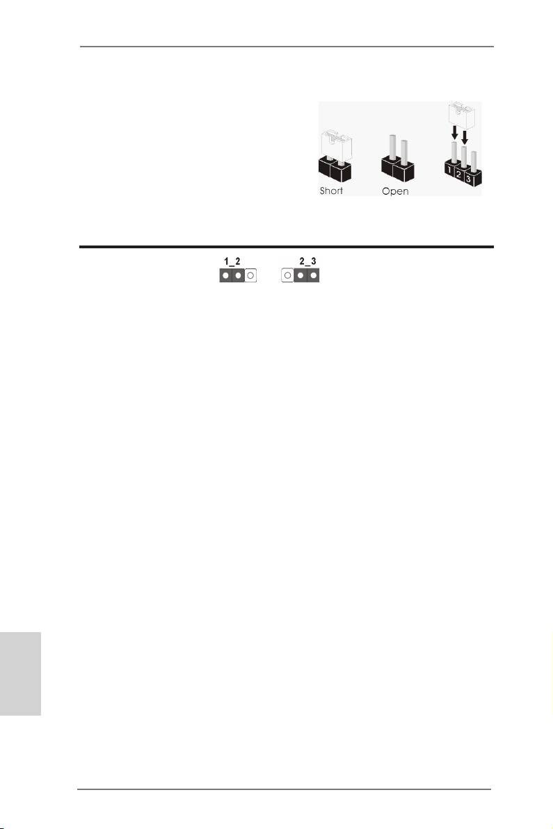
2.5 Jumpers Setup
The illustration shows how jumpers are
setup. When the jumper cap is placed on
pins, the jumper is “Short”. If no jumper cap
is placed on pins, the jumper is “Open”. The
illustration shows a 3-pin jumper whose
pin1 and pin2 are “Short” when jumper cap
is placed on these 2 pins.
Jumper Setting Description
Clear CMOS Jumper
(CLRCMOS1)
(see p.2, No. 38)
Clear CMOSDefault
Note: CLRCMOS1 allows you to clear the data in CMOS. To clear and reset the
system parameters to default setup, please turn off the computer and unplug
the power cord from the power supply. After waiting for 15 seconds, use a
jumper cap to short pin2 and pin3 on CLRCMOS1 for 5 seconds. However,
please do not clear the CMOS right after you update the BIOS. If you need
to clear the CMOS when you just nish updating the BIOS, you must boot
up the system rst, and then shut it down before you do the clear-CMOS ac-
tion. Please be noted that the password, date, time, user default prole, 1394
GUID and MAC address will be cleared only if the CMOS battery is removed.
English
16
ASRock 980DE3/U3S3 Motherboard
2.6 Onboard Headers and Connectors
Onboard headers and connectors are NOT jumpers. Do NOT place
jumper caps over these headers and connectors. Placing jumper caps
over the headers and connectors will cause permanent damage of the
motherboard!
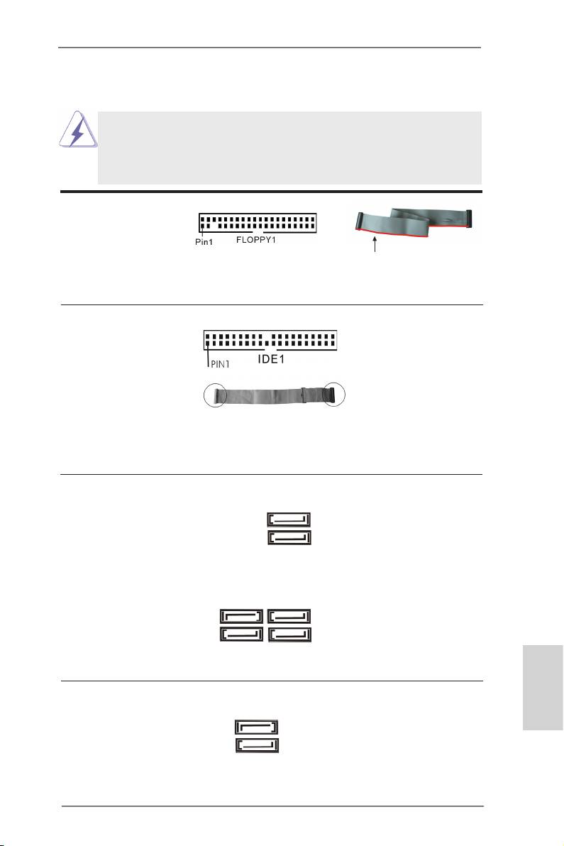
FDD connector
(33-pin FLOPPY1)
(see p.2 No. 27)
the red-striped side to Pin1
Note: Make sure the red-striped side of the cable is plugged into Pin1 side of the
connector.
Primary IDE connector (Black)
(39-pin IDE1, see p.2 No. 36)
connect the blue end
connect the black end
to the motherboard
to the IDE devices
80-conductor ATA 66/100/133 cable
Note: Please refer to the instruction of your IDE device vendor for the details.
Serial ATA2 Connectors These six Serial ATA2 (SATA2)
SATAII_6
(SATAII_1 (PORT 0): see p.2, No. 20)
connectors support SATA data
(PORT 5)
(SATAII_2 (PORT 1): see p.2, No. 19)
cables for internal storage
(SATAII_3 (PORT 2): see p.2, No. 18)
devices. The current SATA2
(SATAII_4 (PORT 3): see p.2, No. 17)
interface allows up to 3.0 Gb/s
SATAII_5
(PORT 4)
(SATAII_5 (PORT 4): see p.2, No. 16)
data transfer rate.
(SATAII_6 (PORT 5): see p.2, No. 15)
SATAII_2 SATAII_4
(PORT 1) (PORT 3)
SATAII_1 SATAII_3
(PORT 0) (PORT 2)
Serial ATA3 Connectors These two Serial ATA3
SATA3_2
English
(SATA3_1 (PORT 6): see p.2, No. 11)
(SATA3) connectors support
(PORT 7)
(SATA3_2 (PORT 7): see p.2, No. 9)
SATA data cables for internal
storage devices. The current
SATA3_1
SATA3 interface allows up to
(PORT 6)
6.0 Gb/s data transfer rate.
17
ASRock 980DE3/U3S3 Motherboard
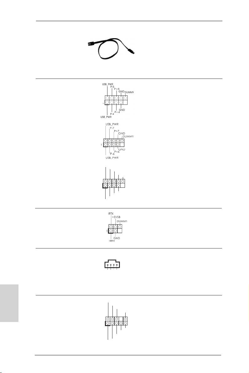
Serial ATA (SATA) Either end of the SATA data
Data Cable cable can be connected to the
(Optional)
SATA / SATA2 / SATA3 hard
disk or the SATA3 connector on
this motherboard.
USB 2.0 Headers Besides four default USB 2.0
(9-pin USB4_5)
ports on the I/O panel, there
(see p.2 No. 22)
are three USB 2.0 headers on
this motherboard. Each USB 2.0
header can support two USB
2.0 ports.
(9-pin USB6_7)
(see p.2 No. 21)
U SB_PWR
(9-pin USB8_9)
P-9
P +9
(see p.2 No. 23)
GND
DUMMY
1
GND
P +8
P-8
U SB_PWR
Infrared Module Header This header supports an
(5-pin IR1)
optional wireless transmitting
(see p.2 No. 31)
and receiving infrared module.
Internal Audio Connectors This connector allows you to
(4-pin CD1)
receive stereo audio input from
(CD1: see p.2 No. 28)
sound sources such as a
CD-ROM, DVD-ROM, TV tuner
card, or MPEG card.
English
Front Panel Audio Header This is an interface for the front
GND
P RESENCE#
(9-pin HD_AUDIO1)
M IC_RET
panel audio cable that allows
OUT_RET
(see p.2 No. 29)
convenient connection and
control of audio devices.
1
O UT2_L
J _SENSE
O UT2_R
M IC2_R
M IC2_L
18
ASRock 980DE3/U3S3 Motherboard
C D -R
GND
GND
C D -L
CD1
1. High Denition Audio supports Jack Sensing, but the panel wire on
the chassis must support HDA to function correctly. Please follow the
instruction in our manual and chassis manual to install your system.
2. If you use AC’97 audio panel, please install it to the front panel audio
header as below:
A. Connect Mic_IN (MIC) to MIC2_L.
B. Connect Audio_R (RIN) to OUT2_R and Audio_L (LIN) to OUT2_L.
C. Connect Ground (GND) to Ground (GND).
D. MIC_RET and OUT_RET are for HD audio panel only. You don’t
need to connect them for AC’97 audio panel.
E. To activate the front mic.
®
For Windows
XP / XP 64-bit OS:
Select “Mixer”. Select “Recorder”. Then click “FrontMic”.
®
TM
TM
For Windows
8 / 8 64-bit / 7 / 7 64-bit / Vista
/ Vista
64-bit OS:
Go to the "FrontMic" Tab in the Realtek Control panel. Adjust
“Recording Volume”.
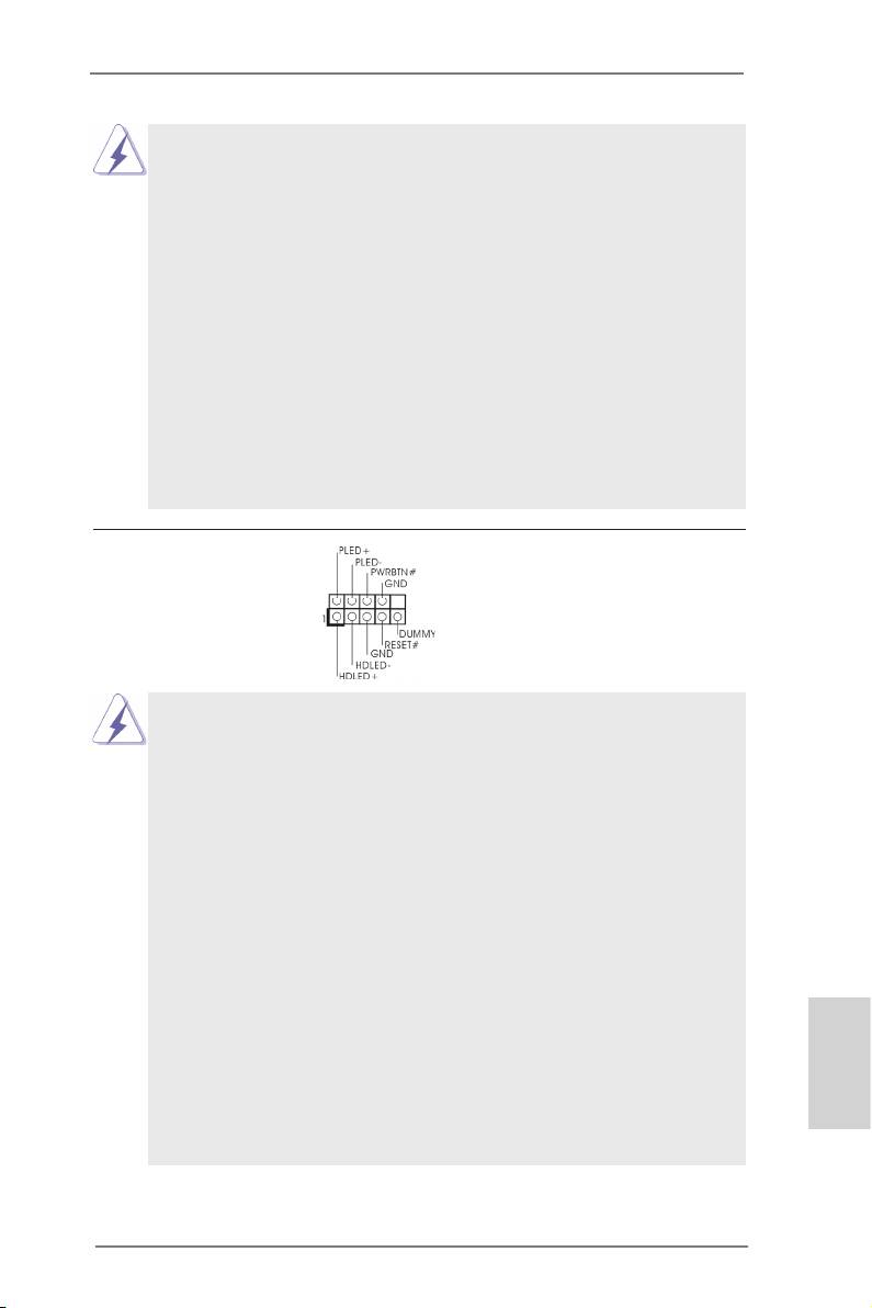
System Panel Header This header accommodates
(9-pin PANEL1)
several system front panel
(see p.2 No. 24)
functions.
Connect the power switch, reset switch and system status indicator
on the chassis to this header according to the pin assignments below.
Note the positive and negative pins before connecting the cables.
PWRBTN (Power Switch):
Connect to the power switch on the chassis front panel. You may con-
gure the way to turn off your system using the power switch.
RESET (Reset Switch):
Connect to the reset switch on the chassis front panel. Press the reset
switch to restart the computer if the computer freezes and fails to per-
form a normal restart.
PLED (System Power LED):
Connect to the power status indicator on the chassis front panel. The
LED is on when the system is operating. The LED keeps blinking
when the sys-tem is in S1 sleep state. The LED is off when the system
is in S3/S4 sleep state or powered off (S5).
HDLED (Hard Drive Activity LED):
English
Connect to the hard drive activity LED on the chassis front panel. The
LED is on when the hard drive is reading or writing data.
19
ASRock 980DE3/U3S3 Motherboard
The front panel design may differ by chassis. A front panel module
mainly consists of power switch, reset switch, power LED, hard drive
activity LED, speaker and etc. When connecting your chassis front
panel module to this header, make sure the wire assignments and the
pin assign-ments are matched correctly.
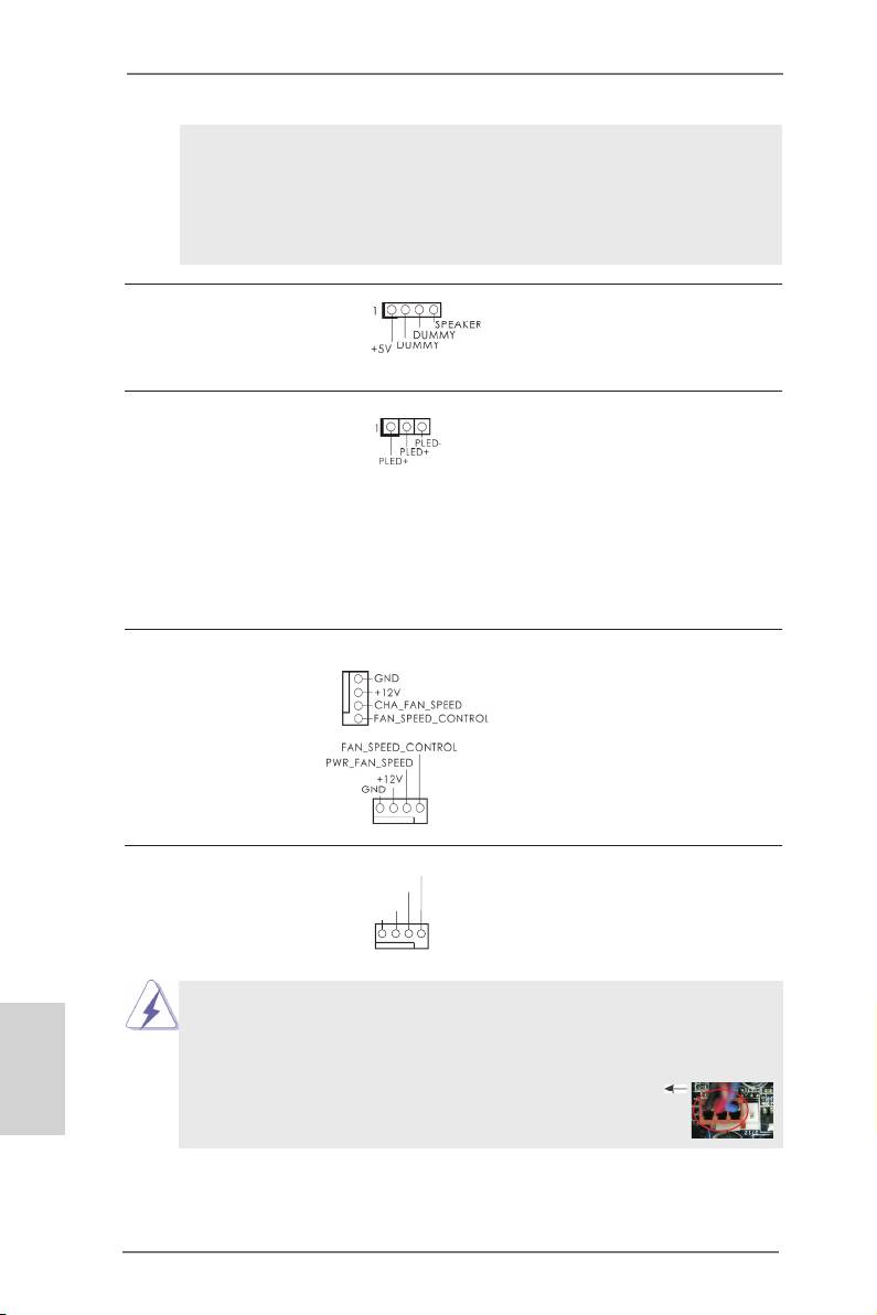
Chassis Speaker Header Please connect the chassis
(4-pin SPEAKER 1)
speaker to this header.
(see p.2 No. 26)
Power LED Header Please connect the chassis
(3-pin PLED1)
power LED to this header to
(see p.2 No. 25)
indicate system power status.
The LED is on when the system
is operating. The LED keeps
blinking in S1 state. The LED is
off in S3/S4 state or S5 state
(power off).
Chassis and Power Fan Connectors Please connect the fan cables
(4-pin CHA_FAN1)
to the fan connectors and
(see p.2 No. 12)
match the black wire to the
ground pin.
(4-pin PWR_FAN1)
(see p.2 No. 2)
CPU Fan Connectors Please connect the CPU fan
FAN_S PEED_CONTROL
CPU_FAN_SPEED
(4-pin CPU_FAN1)
cable to the connector and
+ 12V
(see p.2 No. 3)
GND
match the black wire to the
ground pin.
1 2 3 4
Though this motherboard provides 4-Pin CPU fan (Quiet Fan) support, the 3-Pin
CPU fan still can work successfully even without the fan speed control function.
English
If you plan to connect the 3-Pin CPU fan to the CPU fan connector on this
motherboard, please connect it to Pin 1-3.
Pin 1-3 Connected
3-Pin Fan Installation
20
ASRock 980DE3/U3S3 Motherboard
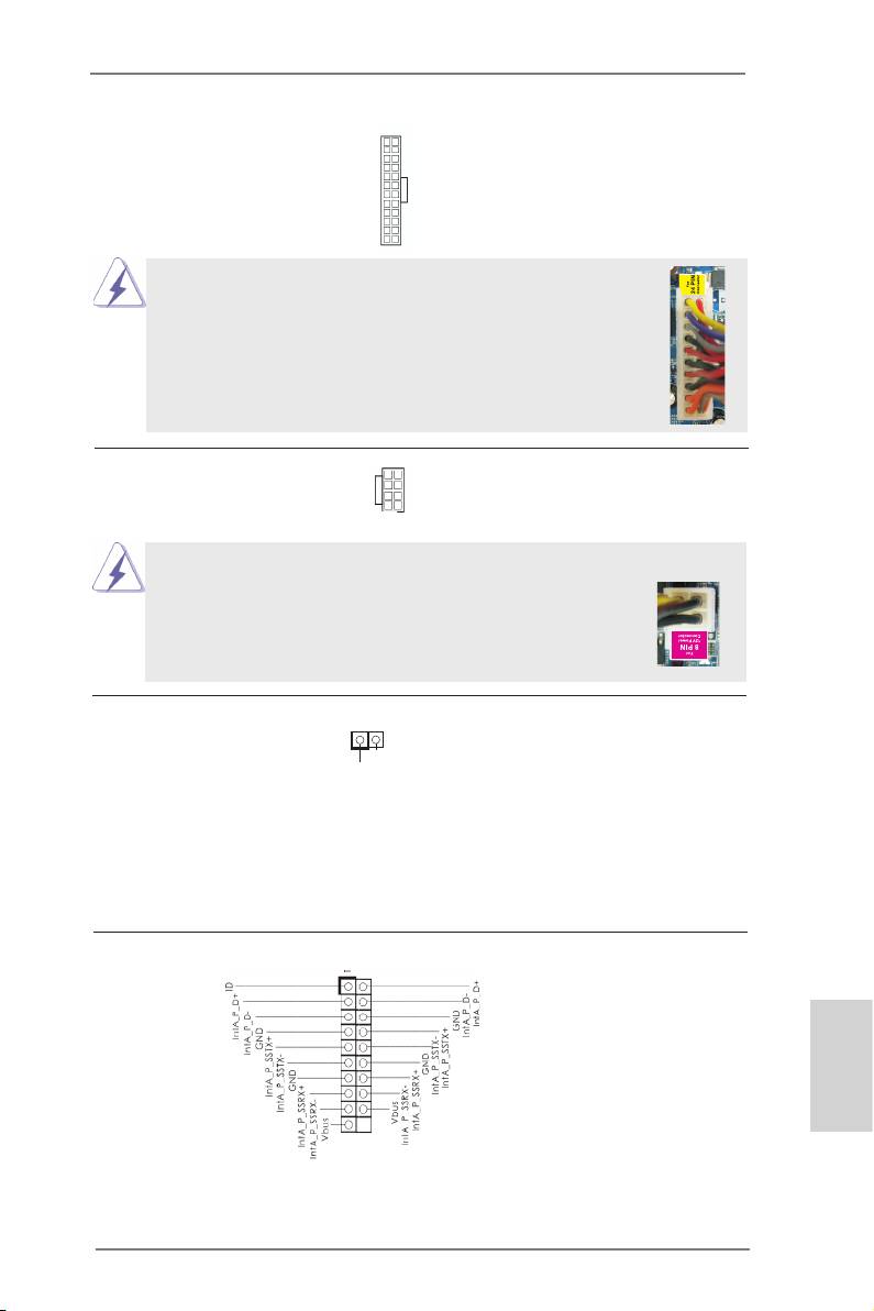
ATX Power Connector Please connect an ATX power
12
24
(24-pin ATXPWR1)
supply to this connector.
(see p.2 No. 10)
1
13
Though this motherboard provides 24-pin ATX power connector,
12
24
it can still work if you adopt a traditional 20-pin ATX power supply.
To use the 20-pin ATX power supply, please plug your power
supply along with Pin 1 and Pin 13.
20-Pin ATX Power Supply Installation
1
13
ATX 12V Power Connector Please connect an ATX 12V
5 1
(8-pin ATX12V1)
power supply to this connector.
(see p.2 No. 1)
8 4
Though this motherboard provides 8-pin ATX 12V power connector, it can still work
if you adopt a traditional 4-pin ATX 12V power supply. To use the
5 1
4-pin ATX power supply, please plug your power supply along with
Pin 1 and Pin 5.
8 4
4-Pin ATX 12V Power Supply Installation
HDMI_SPDIF Header HDMI_SPDIF header, providing
(2-pin HDMI_SPDIF1)
SPDIF audio output to HDMI
1
GN D
(
see p.2 No. 30)
VGA card, allows the system to
SP D IFOUT
connect HDMI Digital TV/
projector/LCD devices. Please
connect the HDMI_SPDIF
connector of HDMI VGA card to
this header.
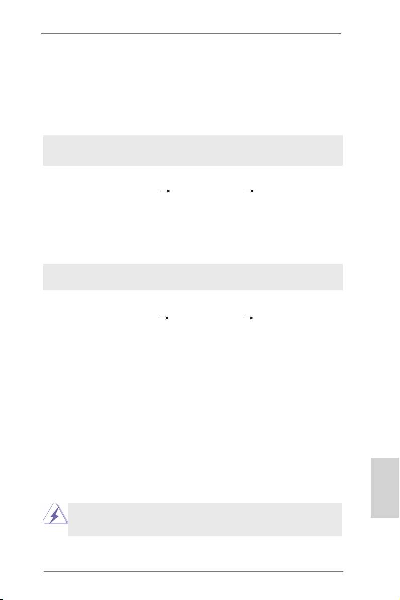
USB 3.0 Header Besides two default USB 3.0
(19-pin USB3_2_3)
ports on the I/O panel, there is
(see p.2 No. 39)
one USB 3.0 header on this
motherboard. This USB 3.0
header can support two USB 3.0
ports.
English
21
ASRock 980DE3/U3S3 Motherboard

2.7 Driver Installation Guide
To install the drivers to your system, please insert the support CD to your optical
drive rst. Then, the drivers compatible to your system can be auto-detected and
listed on the support CD driver page. Please follow the order from up to bottom side
to install those required drivers. Therefore, the drivers you install can work properly.
®
TM
2.8 Installing Windows
8 / 8 64-bit / 7 / 7 64-bit / Vista
/
TM
Vista
64-bit / XP / XP 64-bit With RAID Functions
®
TM
TM
If you want to install Windows
8 / 8 64-bit / 7 / 7 64-bit / Vista
/ Vista
64-bit / XP
/ XP 64-bit on your SATA / SATA2 HDDs with RAID functions, please refer to the
document at the following path in the Support CD for detailed procedures:
..\ RAID Installation Guide
®
TM
2.9 Installing Windows
8 / 8 64-bit / 7 / 7 64-bit / Vista
/
TM
Vista
64-bit / XP / XP 64-bit Without RAID Functions
®
TM
TM
If you want to install Windows
8 / 8 64-bit / 7 / 7 64-bit / Vista
/ Vista
64-bit / XP
/ XP 64-bit OS on your SATA / SATA2 / SATA3 HDDs without RAID functions, please
follow below procedures according to the OS you install.
®
2.9.1 Installing Windows
XP / XP 64-bit Without RAID
Functions
®
If you want to install Windows
XP / XP 64-bit on your SATA / SATA2 / SATA3 HDDs
without RAID functions, please follow below steps.
Using SATA / SATA2 / SATA3 HDDs without NCQ and Hot Plug functions (IDE
mode)
STEP 1: Set up BIOS.
English
A. Enter BIOS SETUP UTILITY Advanced screen Storage Conguration.
B. Set the “SATA Operation Mode” option to [IDE] for SATA2 ports.
Set the “Onboard SATA3 Operation Mode” option to [IDE] for SATA3 ports.
®
STEP 2: Install Windows
XP / XP 64-bit OS on your system.
22
ASRock 980DE3/U3S3 Motherboard
®
TM
2.9.2 Installing Windows
8 / 8 64-bit / 7 / 7 64-bit / Vista
/
TM
Vista
64-bit Without RAID Functions
®
TM
TM
If you want to install Windows
8 / 8 64-bit / 7 / 7 64-bit / Vista
/ Vista
64-bit on
your SATA / SATA2 / SATA3 HDDs without RAID functions, please follow below
steps.
Using SATA / SATA2 / SATA3 HDDs without NCQ and Hot Plug functions (IDE
mode)
STEP 1: Set up BIOS.
A. Enter BIOS SETUP UTILITY Advanced screen Storage Conguration.
B. Set the “SATA Operation Mode” option to [IDE] for SATA2 ports.
Set the “Onboard SATA3 Operation Mode” option to [IDE] for SATA3 ports.
®
TM
TM
STEP 2: Install Windows
8 / 8 64-bit / 7 / 7 64-bit / Vista
/ Vista
64-bit OS on
your system.
Using SATA / SATA2 / SATA3 HDDs with NCQ and Hot Plug functions (AHCI
mode)
STEP 1: Set up BIOS.
A. Enter BIOS SETUP UTILITY Advanced screen Storage Conguration.
B. Set the “SATA Operation Mode” option to [AHCI] for SATA2 ports.
Set the “Onboard SATA3 Operation Mode” option to [AHCI] for SATA3 ports.
®
TM
TM
STEP 2: Install Windows
8 / 8 64-bit / 7 / 7 64-bit / Vista
/ Vista
64-bit OS on
your system.
2.10 Untied Overclocking Technology
This motherboard supports Untied Overclocking Technology, which means during
overclocking, FSB enjoys better margin due to xed PCI / PCIE buses. Before you
enable Untied Overclocking function, please enter “Overclock Mode” option of BIOS
setup to set the selection from [Auto] to [Manual]. Therefore, CPU FSB is untied
during overclocking, but PCI / PCIE buses are in the xed mode so that FSB can
operate under a more stable overclocking environment.
English
Please refer to the warning on page 7 for the possible overclocking risk
before you apply Untied Overclocking Technology.
23
ASRock 980DE3/U3S3 Motherboard
Оглавление
- Motherboard Layout
- I/O Panel
- 1. Introduction
- 2. Installation
- 3. BIOS Information
- 1. Einführung
- 2. BIOS-Information
- 1. Introduction
- 2. Informations sur le BIOS
- 1. Introduzione
- 2. Informazioni sul BIOS
- 1. Introducción
- 2. BIOS Información
- 1. Введение
- 2. Информация о BIOS
- 1. Introdução
- 2. Informações da BIOS
- 1. Giriş
- 2. BIOS Bilgileri
- 1. 제품소개
- 2. 시스템 바이오스 정보
- 1. 主板簡介
- 2. BIOS 信息
- 1. 主機板簡介
- 2. BIOS 訊息
- 1. Penjelasan
