Gigabyte ga-h61m-s: Chapter 2 BIOS Setup
Chapter 2 BIOS Setup: Gigabyte ga-h61m-s
Chapter 2 BIOS Setup
To access the BIOS Setup program, press the <Delete> key during the POST when the power is turned on.
To see more advanced BIOS Setup menu options, you can press <Ctrl> + <F1> in the main menu of the
BIOS Setup program.
To upgrade the BIOS, use either the GIGABYTE Q-Flash or @BIOS utility.
Q-Flash allows the user to quickly and easily upgrade or back up BIOS without entering the operating •
system.
@BIOS is a Windows-based utility that searches and downloads the latest version of BIOS from the •
Internet and updates the BIOS.
Because BIOS ashing is potentially risky, if you do not encounter problems using the current •
version of BIOS, it is recommended that you not ash the BIOS. To ash the BIOS, do it with
caution. Inadequate BIOS ashing may result in system malfunction.
It is recommended that you not alter the default settings (unless you need to) to prevent system •
instability or other unexpected results. Inadequately altering the settings may result in system's
failure to boot. If this occurs, try to clear the CMOS values and reset the board to default values.
(Refer to the "Load Optimized Defaults" section in this chapter or introductions of the battery/
clearing CMOS jumper in Chapter 1 for how to clear the CMOS values.)
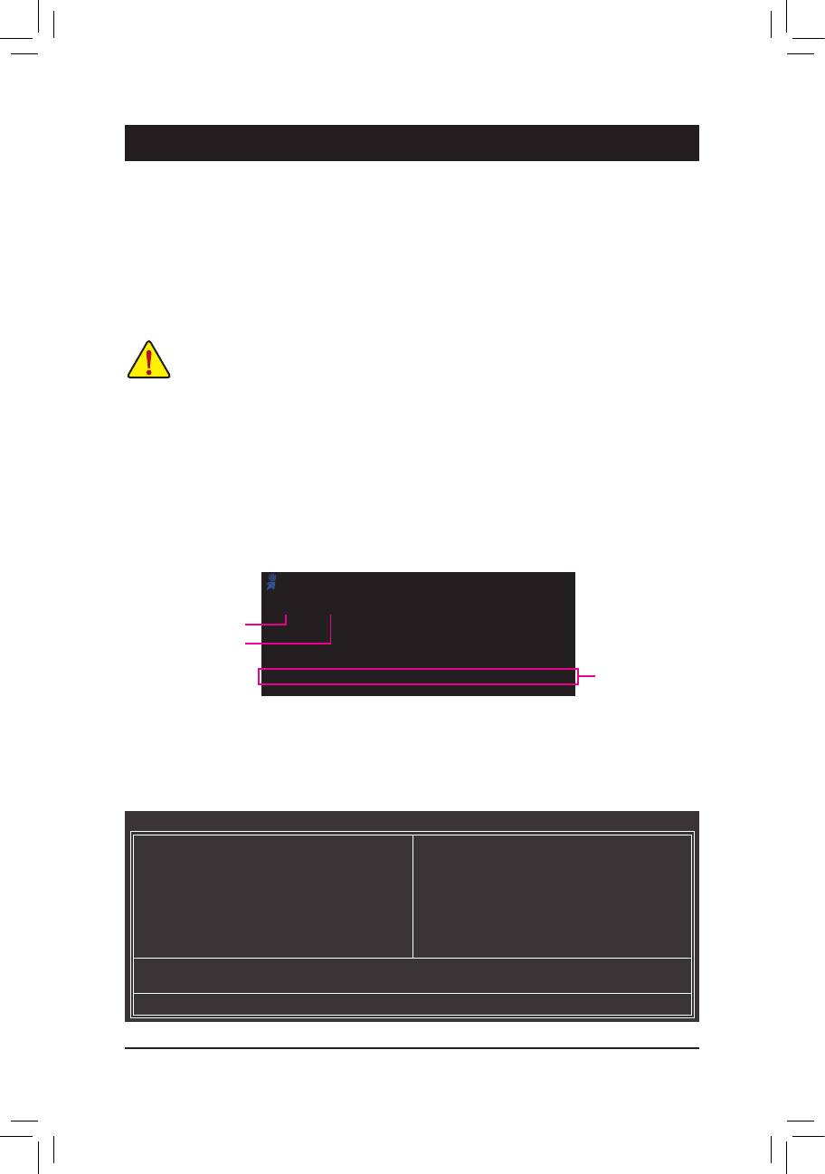
2-1 Startup Screen
The following screens may appear when the computer boots.
Award Modular BIOS v6.00PG
Copyright (C) 1984-2011, Award Software, Inc.
H61M-D2-B3 D13
Motherboard Model
.
.
BIOS Version
.
.
<DEL>: BIOS Setup <F9>: XpressRecovery2 <F12>: Boot Menu <End>: Qflash
Function Keys
01/10/2011-H61-7A89UG0LC-00
2-2 The Main Menu
Once you enter the BIOS Setup program, the Main Menu (as shown below) appears on the screen. Use ar-
row keys to move among the items and press <Enter> to accept or enter a sub-menu.
(Sample BIOS Version: GA-H61M-D2-B3 D13)
CMOS Setup Utility-Copyright (C) 1984-2011 Award Software
MB Intelligent Tweaker(M.I.T.)
Load Fail-Safe Defaults
Standard CMOS Features
Load Optimized Defaults
Advanced BIOS Features
Set Supervisor Password
Integrated Peripherals
Set User Password
Power Management Setup
Save & Exit Setup
PC Health Status
Exit Without Saving
ESC: Quit
: Select Item F11: Save CMOS to BIOS
F8: Q-Flash F10: Save & Exit Setup F12: Load CMOS from BIOS
Change CPU's Clock & Voltage
BIOS Setup - 22 -
If you do not nd the settings you want in the Main Menu or a submenu, press <Ctrl>+<F1> to •
access more advanced options.
When the system is not stable as usual, select the • Load Optimized Defaults item to set your
system to its defaults.
The BIOS Setup menus described in this chapter are for reference only and may differ by BIOS •
version.
The Functions of the <F11> and <F12> keys (For the Main Menu Only)
F11: Save CMOS to BIOS
This function allows you to save the current BIOS settings to a prole. You can create up to 8 proles
(Prole 1-8) and name each prole. First enter the prole name (to erase the default prole name, use
the SPACE key) and then press <Enter> to complete.
F12: Load CMOS from BIOS
If your system becomes unstable and you have loaded the BIOS default settings, you can use this
function to load the BIOS settings from a prole created before, without the hassles of reconguring the
BIOS settings. First select the prole you wish to load, then press <Enter> to complete.
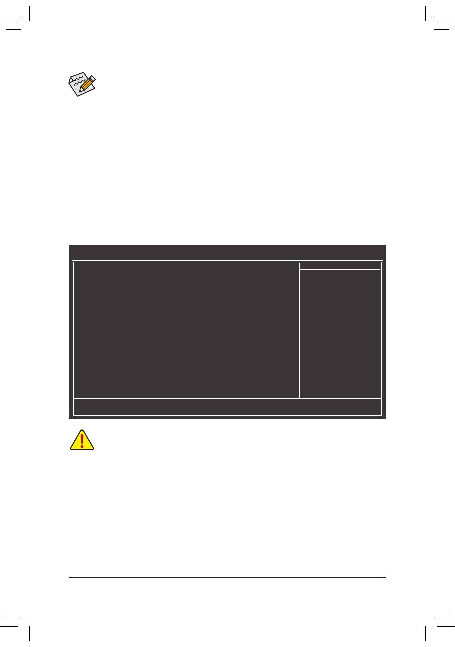
2-3 MB Intelligent Tweaker(M.I.T.)
CMOS Setup Utility-Copyright (C) 1984-2011 Award Software
MB Intelligent Tweaker(M.I.T.)
M.I.T Current Status [Press Enter]
Item Help
Advanced Frequency Settings [Press Enter]
Menu Level
Advanced Memory Settings [Press Enter]
Advanced Voltage Settings [Press Enter]
Miscellaneous Settings [Press Enter]
BIOS Version D13
BCLK 99.80 MHz
CPU Frequency 3094.12 MHz
Memory Frequency 1332.71 MHz
Total Memory Size 1024 MB
o
CPU Temperature 33
C
Vcore 1.200V
DRAM Voltage 1.524V
: Move Enter: Select +/-/PU/PD: Value F10: Save ESC: Exit F1: General Help
F5: Previous Values F6: Fail-Safe Defaults F7: Optimized Defaults
Whether the system will work stably with the overclock/overvoltage settings you made is dependent
on your overall system congurations. Incorrectly doing overclock/overvoltage may result in dam-
age to CPU, chipset, or memory and reduce the useful life of these components. This page is for
advanced users only and we recommend you not to alter the default settings to prevent system
instability or other unexpected results. (Inadequately altering the settings may result in system's
failure to boot. If this occurs, clear the CMOS values and reset the board to default values.)
- 23 - BIOS Setup

CMOS Setup Utility-Copyright (C) 1984-2011 Award Software
MB Intelligent Tweaker(M.I.T.)
M.I.T Current Status [Press Enter]
Item Help
Advanced Frequency Settings [Press Enter]
Menu Level
Advanced Memory Settings [Press Enter]
Advanced Voltage Settings [Press Enter]
Miscellaneous Settings [Press Enter]
BIOS Version D13
BCLK 99.80 MHz
CPU Frequency 3094.12 MHz
Memory Frequency 1332.71 MHz
Total Memory Size 1024 MB
o
CPU Temperature 33
C
Vcore 1.200V
DRAM Voltage 1.524V
: Move Enter: Select +/-/PU/PD: Value F10: Save ESC: Exit F1: General Help
F5: Previous Values F6: Fail-Safe Defaults F7: Optimized Defaults
This section provides information on the BIOS version, CPU base clock, CPU frequency, memory frequency,
total memory size , CPU temperature, Vcore, and memory voltage.
M.I.T. Current Status
This screen provides information on CPU/memory frequencies/parameters.
Advanced Frequency Settings
CMOS Setup Utility-Copyright (C) 1984-2011 Award Software
Advanced Frequency Settings
CPU Clock Ratio [31X]
Item Help
CPU Frequency 3.10GHz (100x31)
Menu Level
Advanced CPU Core Features [Press Enter]
>>>>> Standard Clock Control
System Memory Multiplier (SPD) [Auto]
Memory Frequency (Mhz) 1333 1333
Internal Graphics Clock 1100 [Auto]
: Move Enter: Select +/-/PU/PD: Value F10: Save ESC: Exit F1: General Help
F5: Previous Values F6: Fail-Safe Defaults F7: Optimized Defaults
BIOS Setup - 24 -

Advanced CPU Core Features
CMOS Setup Utility-Copyright (C) 1984-2011 Award Software
Advanced CPU Core Features
CPU Clock Ratio [31X]
Item Help
CPU Frequency 3.10GHz (100x31)
Menu Level
(Note)
Intel(R) Turbo Boost Tech.
[Auto]
(Note)
-Turbo Ratio(1-Core)
34 Auto
(Note)
-Turbo Ratio(2-Core)
33 Auto
(Note)
-Turbo Ratio(3-Core)
33 Auto
(Note)
-Turbo Ratio(4-Core)
32 Auto
-Turbo Power Limit(Watts) 95 [Auto]
-Core Current Limit(Amps) 97 [Auto]
(Note)
CPU Cores Enabled
[All]
(Note)
CPU Multi-Threading
[Enabled]
(Note)
CPU Enhanced Halt (C1E)
[Auto]
(Note)
C3/C6 State Support
[Auto]
(Note)
CPU Thermal Monitor
[Auto]
(Note)
CPU EIST Function
[Auto]
(Note)
Bi-Directional PROCHOT
[Auto]
: Move Enter: Select +/-/PU/PD: Value F10: Save ESC: Exit F1: General Help
F5: Previous Values F6: Fail-Safe Defaults F7: Optimized Defaults
CPU Clock Ratio
Allows you to alter the clock ratio for the installed CPU. The adjustable range is dependent on the CPU
being installed.
CPU Frequency
Displays the current operating CPU frequency.
(Note)
Intel(R) Turbo Boost Tech.
Allows you to determine whether to enable the Intel CPU Turbo Boost technology. Auto lets the BIOS
automatically congure this setting. (Default: Auto)
(Note)
Turbo Ratio (1-Core)/(2-Core)/(3-Core)/(4-Core)
Allows you to set the CPU Turbo ratios for different number of active cores. Auto sets the CPU Turbo
ratios according to the CPU specications. (Default: Auto)
Turbo Power Limit (Watts)
Allows you to set a power limit for CPU Turbo mode. When the CPU power consumption exceeds the
specied power limit, the CPU will automatically reduce the core frequency in order to reduce the power.
Auto sets the power limit according to the CPU specications. (Default: Auto)
Core Current Limit (Amps)
Allows you to set a current limit for CPU Turbo mode. When the CPU current exceeds the specied cur-
rent limit, the CPU will automatically reduce the core frequency in order to reduce the current.
Auto sets the current limit according to the CPU specications. (Default: Auto)
(Note)
CPU Cores Enabled
Allows you to determine whether to enable all CPU cores.
All Enables all CPU cores. (Default)
1 Enables only one CPU core.
2 Enables only two CPU cores.
3 Enables only three CPU cores.
(Note) This item is present only when you install a CPU that supports this feature. For more information
about Intel CPUs' unique features, please visit Intel's website.
- 25 - BIOS Setup

(Note)
CPU Multi-Threading
Allows you to determine whether to enable multi-threading technology when using an Intel CPU that
supports this function. This feature only works for operating systems that support multi-processor mode.
(Default: Enabled)
(Note)
CPU Enhanced Halt (C1E)
Enables or disables Intel CPU Enhanced Halt (C1E) function, a CPU power-saving function in system
halt state. When enabled, the CPU core frequency and voltage will be reduced during system halt state
to decrease power consumption. Auto lets the BIOS automatically congure this setting. (Default: Auto)
(Note)
C3/C6 State Support
Allows you to determine whether to let the CPU enter C3/C6 mode in system halt state. When enabled,
the CPU core frequency and voltage will be reduced during system halt state to decrease power con-
sumption. The C3/C6 state is a more enhanced power-saving state than C1. Auto lets the BIOS auto-
matically congure this setting. (Default: Auto)
(Note)
CPU Thermal Monitor
Enables or disables Intel CPU Thermal Monitor function, a CPU overheating protection function. When
enabled, the CPU core frequency and voltage will be reduced when the CPU is overheated. Auto lets
the BIOS automatically congure this setting. (Default: Auto)
(Note)
CPU EIST Function
Enables or disables Enhanced Intel SpeedStep Technology (EIST). Depending on CPU loading, Intel
EIST technology can dynamically and effectively lower the CPU voltage and core frequency to decrease
average power consumption and heat production. Auto lets the BIOS automatically congure this set-
ting. (Default: Auto)
(Note)
Bi-Directional PROCHOT
Auto Lets the BIOS automatically congure this setting. (Default)
Enabled When the CPU or chipset detects that an overheating is occurring, PROCHOT sig-
nals will be emitted to lower CPU performance to decrease heat production.
Disabled Only allows the CPU to detect whether an overheating is occurring to emit PRO-
CHOT signals.
>>>>> Standard Clock Control
System Memory Multiplier (SPD)
Allows you to set the system memory multiplier. Auto sets memory multiplier according to memory SPD
data. (Default: Auto)
Memory Frequency(Mhz)
The rst memory frequency value is the normal operating frequency of the memory being used; the sec-
ond is the memory frequency that is automatically adjusted according to the System Memory Multiplier
settings.
Internal Graphics Clock
Allows you to set the onboard graphics clock. The adjustable range is from 400 MHz to 3000 MHz. (Default:
Auto)
(Note) This item is present only when you install a CPU that supports this feature. For more information
about Intel CPUs' unique features, please visit Intel's website.
BIOS Setup - 26 -

Advanced Memory Settings
CMOS Setup Utility-Copyright (C) 1984-2011 Award Software
Advanced Memory Settings
System Memory Multiplier (SPD) [Auto]
Item Help
Memory Frequency (Mhz) 1333 1333
Menu Level
Performance Enhance [Turbo]
DRAM Timing Selectable (SPD) [Auto]
ProleDDRVoltage 1.5V
ProleVTTVoltage 1.05V
x Channel Interleaving Auto
x Rank Interleaving Auto
>>>>> Channel A
Channel A Timing Settings [Press Enter]
>>>>> Channel B
Channel B Timing Settings [Press Enter]
: Move Enter: Select +/-/PU/PD: Value F10: Save ESC: Exit F1: General Help
F5: Previous Values F6: Fail-Safe Defaults F7: Optimized Defaults
System Memory Multiplier (SPD), Memory Frequency(Mhz)
The settings under the two items above are synchronous to those under the same items on the Ad-
vanced Frequency Settings menu.
Performance Enhance
Allows the system to operate at three different performance levels.
Standard Lets the system operate at its basic performance level.
Turbo Lets the system operate at its good performance level. (Default)
Extreme Lets the system operate at its best performance level.
DRAM Timing Selectable (SPD)
Quick and Expert allows the Channel Interleaving, Rank Interleaving, Channel A Timing Settings,
and Channel B Timing Settings items to be congurable. Options are: Auto (default), Quick, Expert.
ProleDDRVoltage
Displays the memory voltage as 1.5V.
ProleVTTVoltage
The value displayed here is dependent on the CPU being used.
Channel Interleaving
Enables or disables memory channel interleaving. Enabled allows the system to simultaneously access
different channels of the memory to increase memory performance and stability. Auto lets the BIOS au-
tomatically congure this setting. (Default: Auto)
Rank Interleaving
Enables or disables memory rank interleaving. Enabled allows the system to simultaneously access dif-
ferent ranks of the memory to increase memory performance and stability. Auto lets the BIOS automati-
cally congure this setting. (Default: Auto)
- 27 - BIOS Setup

>>>>> Channel A/B Timing Settings
CMOS Setup Utility-Copyright (C) 1984-2011 Award Software
Channel A Timing Settings
>>>>> Channel A Standard Timing Control
Item Help
x CAS Latency Time 9 Auto
Menu Level
x tRCD 9 Auto
x tRP 9 Auto
x tRAS 24 Auto
>>>>> Channel A Advanced Timing Control
x tRC 33 Auto
x tRRD 4 Auto
x tWTR 5 Auto
x tWR 10 Auto
x tWTP 21 Auto
x tWL 7 Auto
x tRFC 60 Auto
x tRTP 5 Auto
x tFAW 20 Auto
x Command Rate (CMD) 1 Auto
>>>>> Channel A Misc Timing Control
x IO Latency 1 Auto
x Round Trip Latency 34 Auto
: Move Enter: Select +/-/PU/PD: Value F10: Save ESC: Exit F1: General Help
F5: Previous Values F6: Fail-Safe Defaults F7: Optimized Defaults
>>>>> Channel A/B Standard Timing Control
CAS Latency Time
Options are: Auto (default), 5~15.
tRCD
Options are: Auto (default), 1~15.
tRP
Options are: Auto (default), 1~15.
tRAS
Options are: Auto (default), 1~40.
>>>>> Channel A/B Advanced Timing Control
tRC
Options are: Auto (default), 1~63.
tRRD
Options are: Auto (default), 1~15.
tWTR
Options are: Auto (default), 1~15.
tWR
Options are: Auto (default), 1~16.
tWTP
Options are: Auto (default), 1~31.
tWL
Options are: Auto (default), 1~12
tRFC
Options are: Auto (default), 1~255.
tRTP
Options are: Auto (default), 1~15.
tFAW
Options are: Auto (default), 1~63.
BIOS Setup - 28 -

Command Rate(CMD)
Options are: Auto (default), 1~3.
>>>>> Channel A/B Misc Timing Control
IO Latency
Options are: Auto (default), 1~31.
Round Trip Latency
Options are: Auto (default), 1~255.
Advanced Voltage Settings
CMOS Setup Utility-Copyright (C) 1984-2011 Award Software
Advanced Voltage Settings
******
Mother Board Voltage Control
******
Item Help
Voltage Types Normal Current
Menu Level
-----------------------------------------------------------------------------
>>> CPU
Dynamic Vcore(DVID) +0.000V [Auto]
QPI/Vtt Voltage 1.050V [Auto]
Graphics DVID +0.000V [Auto]
>>> MCH/ICH
PCH Core 1.050V [Auto]
DRAM Voltage 1.500V [Auto]
: Move Enter: Select +/-/PU/PD: Value F10: Save ESC: Exit F1: General Help
F5: Previous Values F6: Fail-Safe Defaults F7: Optimized Defaults
>>> CPU
Dynamic Vcore(DVID)
The default is Auto.
QPI/Vtt Voltage
The default is Auto.
Graphics DVID
The default is Auto.
>>> MCH/ICH
PCH Core
The default is Auto.
DRAM Voltage
The default is Auto.
- 29 - BIOS Setup

Miscellaneous Settings
CMOS Setup Utility-Copyright (C) 1984-2011 Award Software
Miscellaneous Settings
Isochronous Support [Enabled]
Item Help
(Note)
Virtualization Technology
[Enabled]
Menu Level
: Move Enter: Select +/-/PU/PD: Value F10: Save ESC: Exit F1: General Help
F5: Previous Values F6: Fail-Safe Defaults F7: Optimized Defaults
Isochronous Support
Determines whether to enable specic streams within the CPU and Chipset. (Default: Enabled)
(Note)
Virtualization Technology
Enables or disables Intel Virtualization Technology. Virtualization enhanced by Intel Virtualization Tech-
nology will allow a platform to run multiple operating systems and applications in independent partitions.
With virtualization, one computer system can function as multiple virtual systems. (Default: Enabled)
(Note) This item is present only when you install a CPU that supports this feature. For more information
about Intel CPUs' unique features, please visit Intel's website.
2-4 Standard CMOS Features
CMOS Setup Utility-Copyright (C) 1984-2011 Award Software
Standard CMOS Features
Date (mm:dd:yy) Mon, Jan 10 2011
Item Help
Time (hh:mm:ss) 22:31:24
Menu Level
IDE Channel 0 Master [None]
IDE Channel 1 Master [None]
IDE Channel 2 Master [None]
IDE Channel 3 Master [None]
Halt On [All, But Keyboard]
Base Memory 640K
Extended Memory 941M
Total Memory 950M
: Move Enter: Select +/-/PU/PD: Value F10: Save ESC: Exit F1: General Help
F5: Previous Values F6: Fail-Safe Defaults F7: Optimized Defaults
Date (mm:dd:yy)
Sets the system date.
Time (hh:mm:ss)
Sets the system time.
IDE Channel 0, 1 Master
IDE Channel 0, 1 Master
Congure your SATA devices by using one of the three methods below:
None If no SATA devices are used, set this item to • None so the system will skip the
detection of the device during the POST for faster system startup.
Auto Lets the BIOS automatically detect SATA devices during the POST. (Default) •
Manual Allows you to manually enter the specications of the hard drive when the hard •
drive access mode is set to CHS.
Access Mode Sets the hard drive access mode. Options are: Auto (default), CHS, LBA, Large.
BIOS Setup - 30 -

IDE Channel 2, 3 Master
Extended IDE Drive
Congure your SATA devices by using one of the two methods below:
Auto Lets the BIOS automatically detect SATA devices during the POST. (Default) •
None If no SATA devices are used, set this item to • None so the system will skip the
detection of the device during the POST for faster system startup.
Access Mode Sets the hard drive access mode. Options are: Auto (default), Large.
The following elds display your hard drive specications. If you wish to enter the parameters manually,
refer to the information on the hard drive.
Capacity Approximate capacity of the currently installed hard drive.
Cylinder Number of cylinders.
Head Number of heads.
Precomp Write precompensation cylinder.
Landing Zone Landing zone.
Sector Number of sectors.
Halt On
Allows you to determine whether the system will stop for an error during the POST.
Options are: "All Errors," "No Errors," "All, But Keyboard". (Default)
Memory
These elds are read-only and are determined by the BIOS POST.
2-5 Advanced BIOS Features
CMOS Setup Utility-Copyright (C) 1984-2011 Award Software
Advanced BIOS Features
Hard Disk Boot Priority [Press Enter]
Item Help
Quick Boot [Disabled]
Menu Level
CD/DVD Boot Option [Auto]
First Boot Device [Hard Disk]
Second Boot Device [CDROM]
Third Boot Device [USB-FDD]
Password Check [Setup]
HDD S.M.A.R.T. Capability [Disabled]
(Note)
Limit CPUID Max. to 3
[Disabled]
(Note)
No-Execute Memory Protect
[Enabled]
Delay For HDD (Secs) [0]
Init Display First [PCIE x16]
Onboard VGA [Enable If No Ext PEG]
On-Chip Frame Buffer Size [64MB+2MB for GTT]
: Move Enter: Select +/-/PU/PD: Value F10: Save ESC: Exit F1: General Help
F5: Previous Values F6: Fail-Safe Defaults F7: Optimized Defaults
Hard Disk Boot Priority
Species the sequence of loading the operating system from the installed hard drives. Use the up or
down arrow key to select a hard drive, then press the plus key <+> (or <PageUp>) or the minus key <-> (or
<PageDown>) to move it up or down on the list. Press <Esc> to exit this menu when nished.
Quick Boot
Enables or disables the quick boot function to speed up the system boot-up process to shorten the wait-
ing time for entering the operating system and to deliver greater efciency for daily use. The settings
™
here synchronize with the settings of the SMART QuickBoot of Smart 6
. (Default: Disabled)
(Note) This item is present only when you install a CPU that supports this feature. For more information
about Intel CPUs' unique features, please visit Intel's website.
- 31 - BIOS Setup

CD/DVD Boot Option
Set this item to EFI if you want to install the operating system to a hard drive larger than 2.2 TB. Make
sure the operating system to be installed supports booting from a GPT partition, such as Windows 7 64-
bit and Windows Server 2003 64-bit. Auto lets the BIOS automatically congure this setting depending
on the hard drive you install. (Default: Auto)
First/Second/Third Boot Device
Species the boot order from the available devices. Use the up or down arrow key to select a device and
press <Enter> to accept. Options are: Hard Disk, CDROM, USB-FDD, USB-ZIP, USB-CDROM, USB-
HDD, Legacy LAN, Disabled.
Password Check
Species whether a password is required every time the system boots, or only when you enter BIOS
Setup. After conguring this item, set the password(s) under the Set Supervisor/User Password item in
the BIOS Main Menu.
Setup A password is only required for entering the BIOS Setup program. (Default)
System A password is required for booting the system and for entering the BIOS Setup program.
HDD S.M.A.R.T. Capability
Enables or disables the S.M.A.R.T. (Self Monitoring and Reporting Technology) capability of your hard
drive. This feature allows your system to report read/write errors of the hard drive and to issue warnings
when a third party hardware monitor utility is installed. (Default: Disabled)
(Note)
Limit CPUID Max. to 3
Allows you to determine whether to limit CPUID maximum value. Set this item to Disabled for Windows
XP operating system; set this item to Enabled for legacy operating system such as Windows NT4.0.
(Default: Disabled)
(Note)
No-Execute Memory Protect
Enables or disables Intel Execute Disable Bit function. This function may enhance protection for the
computer, reducing exposure to viruses and malicious buffer overow attacks when working with its sup-
porting software and system. (Default: Enabled)
Delay For HDD (Secs)
Allows you to set a delay time for the BIOS to initialize the hard drive as the system boots up. The ad-
justable range is from 0 to 15 seconds. (Default: 0)
Init Display First
Species the rst initiation of the monitor display from the installed PCI Express graphics card or the
onboard graphics.
Onboard Sets the onboard graphics as the rst display.
PCIE x16
Sets the PCI Express graphics card on the PCIEX16 slot as the rst display.
(Default)
Onboard VGA
Enables or disables the onboard graphics function.
Enable If No Ext PEG
Activates the onboard graphics only when no PCI Express graphics card is installed. (Default)
Always Enable
Always activates the onboard graphics, whether or not a PCI Express graphics card is installed. If you
wish to set up a dual view conguration, set this item to Always Enable.
On-Chip Frame Buffer Size
Frame buffer size is the total amount of system memory allocated solely for the onboard graphics con-
troller. MS-DOS, for example, will use only this memory for display. Options are: 32MB+2MB for GTT ~
480MB+2MB for GTT. (Default: 64MB+2MB for GTT)
(Note) This item is present only when you install a CPU that supports this feature. For more information
about Intel CPUs' unique features, please visit Intel's website.
BIOS Setup - 32 -

2-6 Integrated Peripherals
CMOS Setup Utility-Copyright (C) 1984-2011 Award Software
Integrated Peripherals
SATA Port0-1 Native Mode [Enabled]
Item Help
USB Controllers [Enabled]
Menu Level
USB Legacy Function [Enabled]
USB Storage Function [Enabled]
Azalia Codec [Auto]
Onboard H/W LAN [Enabled]
SMART LAN [Press Enter]
Onboard LAN Boot ROM [Disabled]
Onboard Serial Port 1 [3F8/IRQ4]
Onboard Parallel Port [378/IRQ7]
Parallel Port Mode [SPP]
: Move Enter: Select +/-/PU/PD: Value F10: Save ESC: Exit F1: General Help
F5: Previous Values F6: Fail-Safe Defaults F7: Optimized Defaults
SATA Port0-1 Native Mode (Intel H61 Chipset)
Species the operating mode of the integrated SATA controllers.
Disabled Allows the SATA controllers to operate in Legacy IDE mode.
In Legacy mode the SATA controllers use dedicated IRQs that cannot be shared with
other device. Set this option to Disabled if you wish to install operating systems that do
not support Native mode.
Enabled
Allows the SATA controllers to operate in Native IDE mode. Enable Native IDE mode if you wish
to install operating systems that support Native mode.
(Default)
USB Controllers
Enables or disables the integrated USB controller. (Default: Enabled)
Disabled will turn off all of the USB functionalities below.
USB Legacy Function
Allows USB keyboard to be used in MS-DOS. (Default: Enabled)
USB Storage Function
Determines whether to detect USB storage devices, including USB ash drives and USB hard drives
during the POST. (Default: Enabled)
Azalia Codec
Enables or disables the onboard audio function. (Default: Auto)
If you wish to install a 3rd party add-in audio card instead of using the onboard audio, set this item to
Disabled.
Onboard H/W LAN
Enables or disables the onboard LAN function. (Default: Enabled) If you wish to install a 3rd party add-in
network card instead of using the onboard LAN, set this item to Disabled.
SMART LAN (LAN Cable Diagnostic Function)
CMOS Setup Utility-Copyright (C) 1984-2011 Award Software
SMART LAN
Start detecting at Port.....
Item Help
Part1-2 Status = Open / Length = 0m
Menu Level
Part3-6 Status = Open / Length = 0m
Part4-5 Status = Open / Length = 0m
Part7-8 Status = Open / Length = 0m
: Move Enter: Select +/-/PU/PD: Value F10: Save ESC: Exit F1: General Help
F5: Previous Values F6: Fail-Safe Defaults F7: Optimized Defaults
This motherboard incorporates cable diagnostic feature designed to detect the status of the attached LAN
cable. This feature will detect cabling issue and report the approximate distance to the fault or short.
- 33 - BIOS Setup

Onboard LAN Boot ROM
Allows you to decide whether to activate the boot ROM integrated with the onboard LAN chip.
(Default: Disabled)
Onboard Serial Port 1
Enables or disables the rst serial port and species its base I/O address and corresponding interrupt.
Options are: Auto, 3F8/IRQ4 (default), 2F8/IRQ3, 3E8/IRQ4, 2E8/IRQ3, Disabled.
Onboard Parallel Port
Enables or disables the onboard parallel port (LPT) and species its base I/O address and correspond-
ing interrupt. Options are: 378/IRQ7 (default), 278/IRQ5, 3BC/IRQ7, Disabled.
Parallel Port Mode
Selects an operating mode for the onboard parallel (LPT) port. Options are: SPP (Standard Parallel Port)
(default), EPP (Enhanced Parallel Port), ECP (Extended Capabilities Port), ECP+EPP.
2-7 Power Management Setup
CMOS Setup Utility-Copyright (C) 1984-2011 Award Software
Power Management Setup
ACPI Suspend Type [S3(STR)]
Item Help
Soft-Off by PWR-BTTN [Instant-Off]
Menu Level
PME Event Wake Up [Enabled]
Power On by Ring [Enabled]
Resume by Alarm [Disabled]
x Date (of Month) Alarm Everyday
x Time (hh:mm:ss) Alarm 0 : 0 : 0
(Note)
HPET Support
[Enabled]
(Note)
HPET Mode
[32-bit mode]
Power On By Mouse [Disabled]
Power On By Keyboard [Disabled]
x KB Power ON Password Enter
AC Back Function [Soft-Off]
ErP Support [Disabled]
: Move Enter: Select +/-/PU/PD: Value F10: Save ESC: Exit F1: General Help
F5: Previous Values F6: Fail-Safe Defaults F7: Optimized Defaults
ACPI Suspend Type
Species the ACPI sleep state when the system enters suspend.
S1(POS) Enables the system to enter the ACPI S1 (Power on Suspend) sleep state.
In S1 sleep state, the system appears suspended and stays in a low power mode.
The system can be resumed at any time.
S3(STR) Enables the system to enter the ACPI S3 (Suspend to RAM) sleep state (default).
In S3 sleep state, the system appears to be off and consumes less power than in the
S1 state. When signaled by a wake-up device or event, the system resumes to its
working state exactly where it was left off.
Soft-Off by PWR-BTTN
Congures the way to turn off the computer in MS-DOS mode using the power button.
Instant-Off Press the power button and then the system will be turned off instantly. (Default)
Delay 4 Sec. Press and hold the power button for 4 seconds to turn off the system. If the power
button is pressed for less than 4 seconds, the system will enter suspend mode.
(Note) Supported on Windows 7/Vista operating system only.
BIOS Setup - 34 -

PME Event Wake Up
Allows the system to be awakened from an ACPI sleep state by a wake-up signal from a PCI or PCIe de-
vice. Note: To use this function, you need an ATX power supply providing at least 1A on the +5VSB lead.
(Default: Enabled)
Power On by Ring
Allows the system to be awakened from an ACPI sleep state by a wake-up signal from a modem that
supports wake-up function. (Default: Enabled)
Resume by Alarm
Determines whether to power on the system at a desired time. (Default: Disabled)
If enabled, set the date and time as following:
Date (of Month) Alarm: Turn on the system at a specic time on each day or on a specic day in a month.
Time (hh: mm: ss) Alarm: Set the time at which the system will be powered on automatically.
Note: When using this function, avoid inadequate shutdown from the operating system or removal of the
AC power, or the settings may not be effective.
(Note)
HPET Support
Enables or disables High Precision Event Timer (HPET) for Windows 7/Vista operating system.
(Default: Enabled)
(Note)
HPET Mode
Allows you to select the HPET mode for your Windows 7/Vista operating system. Select 32-bit mode
when you install 32-bit Windows 7/Vista; select 64-bit mode when you install 64-bit Windows 7/Vista.
This item is congurable only when the HPET Support is set to Enabled. (Default: 32-bit mode)
Power On By Mouse
Allows the system to be turned on by a PS/2 mouse wake-up event.
Note: To use this function, you need an ATX power supply providing at least 1A on the +5VSB lead.
Disabled Disables this function. (Default)
Double Click Double click on left button on the PS/2 mouse to turn on the system.
Power On By Keyboard
Allows the system to be turned on by a PS/2 keyboard wake-up event.
Note: you need an ATX power supply providing at least 1A on the +5VSB lead.
Disabled Disables this function. (Default)
Password Set a password with 1~5 characters to turn on the system.
Keyboard 98 Press POWER button on the Windows 98 keyboard to turn on the system.
KB Power ON Password
Set the password when Power On by Keyboard is set to Password. Press <Enter> on this item and set
a password with up to 5 characters and then press <Enter> to accept. To turn on the system, enter the
password and press <Enter>.
Note: To cancel the password, press <Enter> on this item. When prompted for the password, press
<Enter> again without entering the password to clear the password settings.
AC Back Function
Determines the state of the system after the return of power from an AC power loss.
Soft-Off The system stays off upon the return of the AC power. (Default)
Full-On The system is turned on upon the return of the AC power.
Memory The system returns to its last known awake state upon the return of the AC power.
ErP Support
Determines whether to let the system consume less than 1W power in S5 (shutdown) state. (Default: Disabled)
Note: When this item is set to Enabled, the following four functions will become unavailable:
PME event wake up, power on by mouse, power on by keyboard, and wake on LAN.
(Note) Supported on Windows 7/Vista operating system only.
- 35 - BIOS Setup

2-8 PC Health Status
CMOS Setup Utility-Copyright (C) 1984-2011 Award Software
PC Health Status
Reset Case Open Status [Disabled]
Item Help
Case Opened No
Menu Level
Vcore 1.172V
DDR15V 1.516V
+12V 11.779V
Vtt 1.076V
o
Current System Temperature 30
C
o
Current CPU Temperature 47
C
Current CPU FAN Speed 3375 RPM
Current SYSTEM FAN Speed 0 RPM
CPU Warning Temperature [Disabled]
CPU FAN Fail Warning [Disabled]
SYSTEM FAN Fail Warning [Disabled]
CPU Smart FAN Control [Normal]
o
x Slope PWM 1.75 PWM value /
C
CPU Smart FAN Mode [Auto]
: Move Enter: Select +/-/PU/PD: Value F10: Save ESC: Exit F1: General Help
F5: Previous Values F6: Fail-Safe Defaults F7: Optimized Defaults
Reset Case Open Status
Keeps or clears the record of previous chassis intrusion status. Enabled clears the record of previous
chassis intrusion status and the Case Opened eld will show "No" at next boot. (Default: Disabled)
Case Opened
Displays the detection status of the chassis intrusion detection device attached to the motherboard CI
header. If the system chassis cover is removed, this eld will show "Yes", otherwise it will show "No". To
clear the chassis intrusion status record, set Reset Case Open Status to Enabled, save the settings to
the CMOS, and then restart your system.
Current Voltage(V) Vcore/DDR15V/+12V/Vtt
Displays the current system voltages.
Current System/CPU Temperature
Displays current system/CPU temperature.
Current CPU/SYSTEM FAN Speed (RPM)
Displays current CPU/system fan speed.
CPU Warning Temperature
Sets the warning threshold for CPU temperature. When CPU temperature exceeds the threshold,
o
o
o
o
o
o
BIOS will emit warning sound. Options are: Disabled (default), 60
C/140
F, 70
C/158
F, 80
C/176
F,
o
o
90
C/194
F.
CPU/SYSTEM FAN Fail Warning
Allows the system to emit warning sound if the CPU/system fan is not connected or fails. Check the fan
condition or fan connection when this occurs. (Default: Disabled)
CPU Smart FAN Control
Allows you to determine whether to enable the CPU fan speed control function and adjust the fan speed.
Normal Allows the CPU fan to run at different speeds according to the CPU temperature. You can
adjust the fan speed with EasyTune based on your system requirements. (Default)
Silent Allows the CPU fan to run at slow speeds.
Manual Allows you to control the CPU fan speed under the Slope PWM item.
Disabled Allows the CPU fan to run at full speeds.
BIOS Setup - 36 -

Slope PWM
Allows you to control the CPU fan speed. This item is congurable only when CPU Smart FAN Control
o
o
is set to Manual. Options are: 0.75 PWM value /
C ~ 2.50 PWM value /
C.
CPU Smart FAN Mode
Species how to control CPU fan speed. This item is congurable only when CPU Smart FAN Control
is enabled.
Auto Lets the BIOS automatically detect the type of CPU fan installed and sets the optimal
CPU fan control mode. (Default)
Voltage Sets Voltage mode for a 3-pin CPU fan.
PWM Sets PWM mode for a 4-pin CPU fan.
Note: The Voltage mode can be set for a 3-pin CPU fan or a 4-pin CPU fan. However, for a 4-pin CPU
fan that is not designed following Intel PWM fan specications, selecting PWM mode may not effectively
reduce the fan speed.
2-9 Load Fail-Safe Defaults
CMOS Setup Utility-Copyright (C) 1984-2011 Award Software
MB Intelligent Tweaker(M.I.T.)
Load Fail-Safe Defaults
Standard CMOS Features
Load Optimized Defaults
Advanced BIOS Features
Set Supervisor Password
Integrated Peripherals
Set User Password
Power Management Setup
Load Fail-Safe Defaults (Y/N)? N
Save & Exit Setup
PC Health Status
Exit Without Saving
ESC: Quit
: Select Item F11: Save CMOS to BIOS
F8: Q-Flash F10: Save & Exit Setup F12: Load CMOS from BIOS
Load Fail-Safe Defaults
Press <Enter> on this item and then press the <Y> key to load the safest BIOS default settings.
In case system instability occurs, you may try to load Fail-Safe defaults, which are the safest and most stable
BIOS settings for the motherboard.
2-10 Load Optimized Defaults
CMOS Setup Utility-Copyright (C) 1984-2011 Award Software
MB Intelligent Tweaker(M.I.T.)
Load Fail-Safe Defaults
Standard CMOS Features
Load Optimized Defaults
Advanced BIOS Features
Set Supervisor Password
Integrated Peripherals
Set User Password
Power Management Setup
Load Optimized Defaults (Y/N)? N
Save & Exit Setup
PC Health Status
Exit Without Saving
ESC: Quit
: Select Item F11: Save CMOS to BIOS
F8: Q-Flash F10: Save & Exit Setup F12: Load CMOS from BIOS
Load Optimized Defaults
Press <Enter> on this item and then press the <Y> key to load the optimal BIOS default settings.
The BIOS defaults settings help the system to operate in optimum state. Always load the Optimized defaults
after updating the BIOS or after clearing the CMOS values.
- 37 - BIOS Setup

2-11 Set Supervisor/User Password
CMOS Setup Utility-Copyright (C) 1984-2011 Award Software
MB Intelligent Tweaker(M.I.T.)
Load Fail-Safe Defaults
Standard CMOS Features
Load Optimized Defaults
Advanced BIOS Features
Set Supervisor Password
Integrated Peripherals
Set User Password
Power Management Setup
Enter Password:
Save & Exit Setup
PC Health Status
Exit Without Saving
ESC: Quit
: Select Item F11: Save CMOS to BIOS
F8: Q-Flash F10: Save & Exit Setup F12: Load CMOS from BIOS
Change/Set/Disable Password
Press <Enter> on this item and type the password with up to 8 characters and then press <Enter>. You will
be requested to conrm the password. Type the password again and press <Enter>.
The BIOS Setup program allows you to specify two separate passwords:
Supervisor Password
When a system password is set and the Password Check item in Advanced BIOS Features is set to
Setup, you must enter the supervisor password for entering BIOS Setup and making BIOS changes.
When the Password Check item is set to System, you must enter the supervisor password (or user
password) at system startup and when entering BIOS Setup.
User Password
When the Password Check item is set to System, you must enter the supervisor password (or user
password) at system startup to continue system boot. In BIOS Setup, you must enter the supervisor
password if you wish to make changes to BIOS settings. The user password only allows you to view the
BIOS settings but not to make changes.
To clear the password, press <Enter> on the password item and when requested for the password, press
<Enter> again. The message "PASSWORD DISABLED" will appear, indicating the password has been can-
celled.
2-12 Save & Exit Setup
CMOS Setup Utility-Copyright (C) 1984-2011 Award Software
MB Intelligent Tweaker(M.I.T.)
Load Fail-Safe Defaults
Standard CMOS Features
Load Optimized Defaults
Save to CMOS and EXIT (Y/N)? Y
Advanced BIOS Features
Set Supervisor Password
Integrated Peripherals
Set User Password
Power Management Setup
Save & Exit Setup
PC Health Status
Exit Without Saving
ESC: Quit
: Select Item F11: Save CMOS to BIOS
F8: Q-Flash F10: Save & Exit Setup F12: Load CMOS from BIOS
Save Data to CMOS
Press <Enter> on this item and press the <Y> key. This saves the changes to the CMOS and exits the BIOS
Setup program. Press <N> or <Esc> to return to the BIOS Setup Main Menu.
BIOS Setup - 38 -


