Gigabyte ga-h61m-s: Chapter 1 Hardware Installation
Chapter 1 Hardware Installation: Gigabyte ga-h61m-s

Chapter 1 Hardware Installation
1-1 Installation Precautions
The motherboard contains numerous delicate electronic circuits and components which can
become damaged as a result of electrostatic discharge (ESD). Prior to installation, carefully read
the user's manual and follow these procedures:
Prior to installation, do not remove or break motherboard S/N (Serial Number) sticker or •
warranty sticker provided by your dealer. These stickers are required for warranty validation.
Always remove the AC power by unplugging the power cord from the power outlet before •
installing or removing the motherboard or other hardware components.
When connecting hardware components to the internal connectors on the motherboard, •
make sure they are connected tightly and securely.
When handling the motherboard, avoid touching any metal leads or connectors. •
It is best to wear an electrostatic discharge (ESD) wrist strap when handling electronic com- •
ponents such as a motherboard, CPU or memory. If you do not have an ESD wrist strap,
keep your hands dry and rst touch a metal object to eliminate static electricity.
Prior to installing the motherboard, please have it on top of an antistatic pad or within an •
electrostatic shielding container.
Before unplugging the power supply cable from the motherboard, make sure the power sup- •
ply has been turned off.
Before turning on the power, make sure the power supply voltage has been set according to •
the local voltage standard.
Before using the product, please verify that all cables and power connectors of your hard- •
ware components are connected.
To prevent damage to the motherboard, do not allow screws to come in contact with the •
motherboard circuit or its components.
Make sure there are no leftover screws or metal components placed on the motherboard or •
within the computer casing.
Do not place the computer system on an uneven surface •
.
Do not place the computer system in a high-temperature environment. •
Turning on the computer power during the installation process can lead to damage to sys- •
tem components as well as physical harm to the user.
If you are uncertain about any installation steps or have a problem related to the use of the •
product, please consult a certied computer technician.
Hardware Installation - 8 -
1-2 ProductSpecications
CPU Support for Intel
®
Core
™
i7 processors/Intel
®
Core
™
i5 processors/
Intel
®
Core
™
i3 processors/Intel
®
Pentium
®
processors/Intel
®
Celeron
®
processors
in the LGA1155 package
(Go to GIGABYTE's website for the latest CPU support list.)
L3 cache varies with CPU
Chipset Intel
®
H61 Express Chipset
Memory 2 x 1.5V DDR3 DIMM sockets supporting up to 16 GB of system memory
* Due to Windows 32-bit operating system limitation, when more than 4 GB of physical
memory is installed, the actual memory size displayed will be less than 4 GB.
Dual channel memory architecture
Support for DDR3 1333/1066/800 MHz memory modules
Support for non-ECC memory modules
(Go to GIGABYTE's website for the latest supported memory speeds and memory
modules.)
Onboard
Integrated in the Chipset:
Graphics
- 1 x D-Sub port
- 1 x DVI-D port, supporting a maximum resolution of 1920x1200
* The DVI-D port does not support D-Sub connection by adapter.
Audio Realtek ALC889 codec
High Denition Audio
2/4/5.1/7.1-channel
* To enable 7.1-channel audio, you have to use an HD front panel audio module and
enable the multi-channel audio feature through the audio driver.
LAN 1 x Realtek RTL8111E chip (10/100/1000 Mbit)
Expansion Slots 1 x PCI Express x16 slot, running at x16
3 x PCI Express x1 slots
(All PCI Express slots conform to PCI Express 2.0 standard.)
Storage Interface Chipset:
- 4 x SATA 3Gb/s connectors supporting up to 4 SATA 3Gb/s devices
USB Chipset:
- Up to 10 USB 2.0/1.1 ports (6 on the back panel, 4 via the USB brackets
connected to the internal USB headers)
Internal
1 x 24-pin ATX main power connector
Connectors
1 x 4-pin ATX 12V power connector
4 x SATA 3Gb/s connectors
1 x CPU fan header
1 x system fan header
1 x front panel header
1 x front panel audio header
2 x USB 2.0/1.1 headers
"*" The GA-H61M-D2-B3 adopts All-Solid Capacitor design.
- 9 - Hardware Installation
Internal
1 x parallel port header
Connectors
1 x serial port header
1 x power LED header
1 x chassis intrusion header
1 x clearing CMOS jumper
Back Panel
1 x PS/2 keyboard port
Connectors
1 x PS/2 mouse port
1 x D-Sub port
1 x DVI-D port
6 x USB 2.0/1.1 ports
1 x RJ-45 port
3 x audio jacks (Line In/Line Out/Microphone)
I/O Controller iTE IT8728 chip
Hardware
System voltage detection
Monitor
CPU/System temperature detection
CPU/System fan speed detection
CPU/System fan speed control
* Whether the CPU/system fan speed control function is supported will depend on
the CPU/system cooler you install.
BIOS 2 x 32 Mbit ash
Use of licensed AWARD BIOS
Support for DualBIOS
™
PnP 1.0a, DMI 2.0, SM BIOS 2.4, ACPI 1.0b
Unique Features Support for @BIOS
Support for Q-Flash
Support for Xpress BIOS Rescue
Support for Download Center
Support for Xpress Install
Support for Xpress Recovery2
Support for EasyTune
* Available functions in EasyTune may differ by motherboard model.
Support for Smart 6
™
Support for Auto Green
Support for ON/OFF Charge
Support for Cloud OC
Support for Q-Share
Bundled
Norton Internet Security (OEM version)
Software
Operating
Support for Microsoft
®
Windows 7/Vista/XP
System
Form Factor Micro ATX Form Factor; 24.4cm x 19.5cm
* GIGABYTE reserves the right to make any changes to the product specications and product-related information
without prior notice.
Hardware Installation - 10 -
1-3 Installing the CPU and CPU Cooler
Read the following guidelines before you begin to install the CPU:
Make sure that the motherboard supports the CPU. •
(Go to GIGABYTE's website for the latest CPU support list.)
Always turn off the computer and unplug the power cord from the power outlet before installing •
the CPU to prevent hardware damage.
Locate the pin one of the CPU. The CPU cannot be inserted if oriented incorrectly. (Or you may •
locate the notches on both sides of the CPU and alignment keys on the CPU socket.)
Apply an even and thin layer of thermal grease on the surface of the CPU. •
Do not turn on the computer if the CPU cooler is not installed, otherwise overheating and dam- •
age of the CPU may occur.
Set the CPU host frequency in accordance with the CPU specications. It is not recommended •
that the system bus frequency be set beyond hardware specications since it does not meet the
standard requirements for the peripherals. If you wish to set the frequency beyond the standard
specications, please do so according to your hardware specications including the CPU, graph-
ics card, memory, hard drive, etc.
Installing the CPU
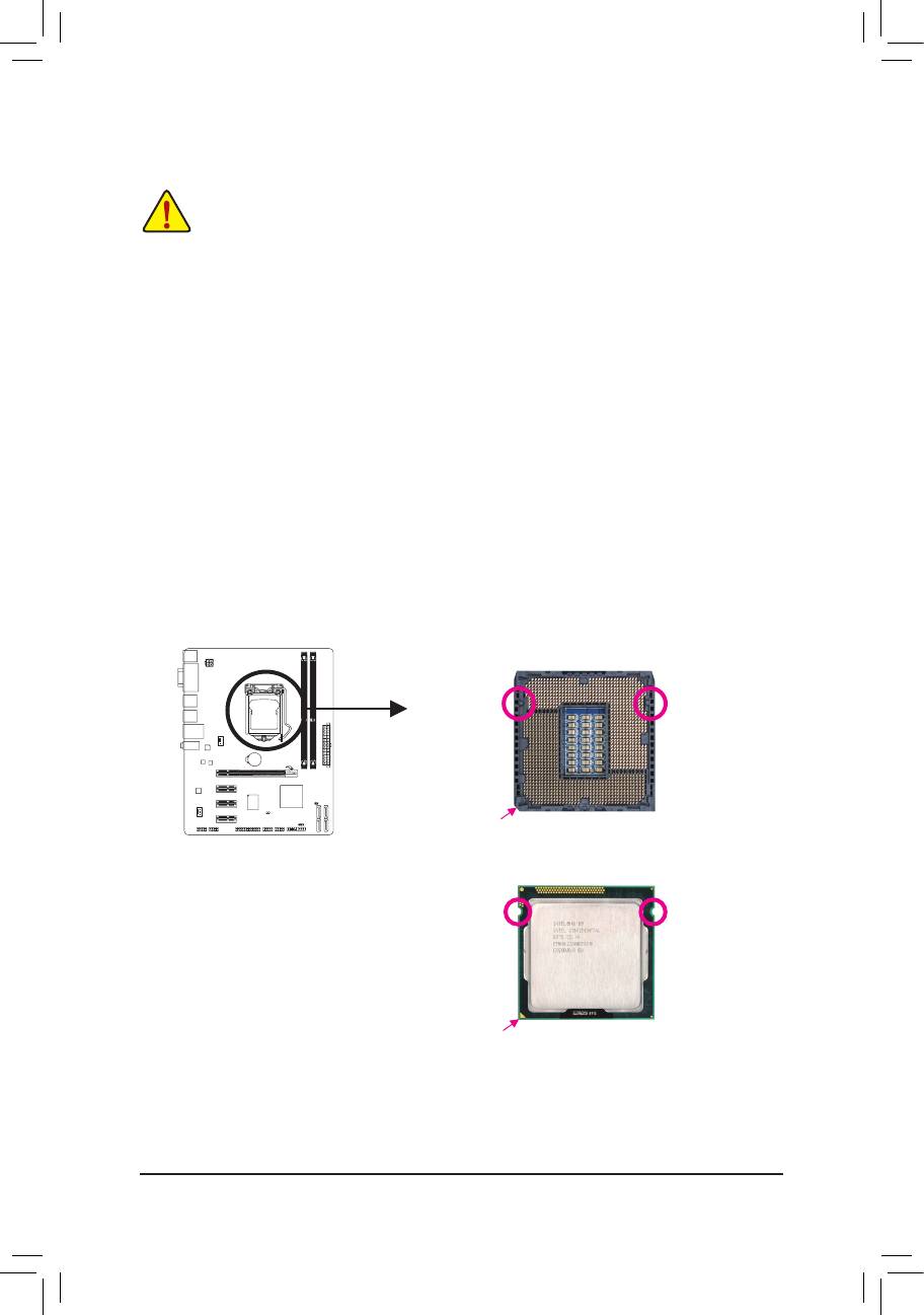
A. Locate the alignment keys on the motherboard CPU socket and the notches on the CPU.
LGA1155 CPU Socket
Alignment KeyAlignment Key
Pin One Corner of the CPU Socket
LGA1155 CPU
Notch
Notch
Triangle Pin One Marking on the CPU
- 11 - Hardware Installation
1-4 Installing the Memory
Read the following guidelines before you begin to install the memory:
Make sure that the motherboard supports the memory. It is recommended that memory of the •
same capacity, brand, speed, and chips be used.
(Go to GIGABYTE's website for the latest supported memory speeds and memory modules.)
Always turn off the computer and unplug the power cord from the power outlet before installing •
the memory to prevent hardware damage.
Memory modules have a foolproof design. A memory module can be installed in only one direc- •
tion. If you are unable to insert the memory, switch the direction.
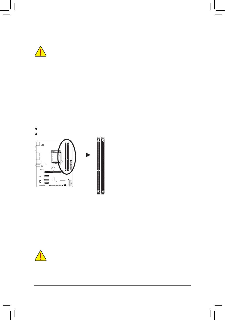
DualChannelMemoryConguration
This motherboard provides two DDR3 memory sockets and supports Dual Channel Technology. After the
memory is installed, the BIOS will automatically detect the specications and capacity of the memory. En-
abling Dual Channel memory mode will double the original memory bandwidth.
The two DDR3 memory sockets are divided into two channels and each channel has one memory socket as
following:
Channel A: DDR3_1
Channel B: DDR3_2
DDR3_1
DDR3_2
Due to CPU limitations, read the following guidelines before installing the memory in Dual Channel mode.
Dual Channel mode cannot be enabled if only one DDR3 memory module is installed.1.
When enabling Dual Channel mode with two memory modules, it is recommended that memory of 2.
the same capacity, brand, speed, and chips be used for optimum performance.
1-5 Installing an Expansion Card
Read the following guidelines before you begin to install an expansion card:
• Make sure the motherboard supports the expansion card. Carefully read the manual that came
with your expansion card.
• Always turn off the computer and unplug the power cord from the power outlet before installing
an expansion card to prevent hardware damage.
Hardware Installation - 12 -
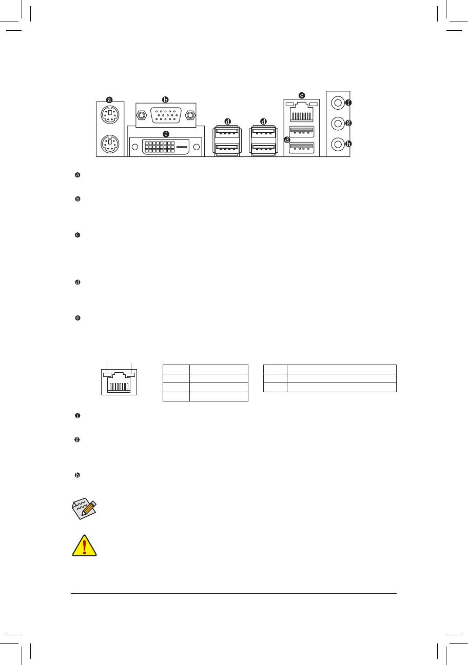
1-6 Back Panel Connectors
PS/2 Keyboard and PS/2 Mouse Port
Use the upper port (green) to connect a PS/2 mouse and the lower port (purple) to connect a PS/2 keyboard.
D-Sub Port
The D-Sub port supports a 15-pin D-Sub connector. Connect a monitor that supports D-Sub connection
to this port.
(Note)
DVI-D Port
The DVI-D port conforms to the DVI-D specication and supports a maximum resolution of 1920x1200
(the actual resolutions supported depend on the monitor being used). Connect a monitor that supports
DVI-D connection to this port.
USB 2.0/1.1 Port
The USB port supports the USB 2.0/1.1 specication. Use this port for USB devices such as a USB key-
board/mouse, USB printer, USB ash drive and etc.
RJ-45 LAN Port
The Gigabit Ethernet LAN port provides Internet connection at up to 1 Gbps data rate. The following
describes the states of the LAN port LEDs.
Connection/
Speed LED
Activity LED
Activity LED:Connection/Speed LED:
State Description
State Description
Orange 1 Gbps data rate
Blinking Data transmission or receiving is occurring
Green 100 Mbps data rate
Off No data transmission or receiving is occurring
Off 10 Mbps data rate
LAN Port
Line In Jack (Blue)
The default line in jack. Use this audio jack for line in devices such as an optical drive, walkman, etc.
Line Out Jack (Green)
The default line out jack. Use this audio jack for a headphone or 2-channel speaker. This jack can be
used to connect front speakers in a 4/5.1/7.1-channel audio conguration.
Mic In Jack (Pink)
The default Mic in jack. Microphones must be connected to this jack.
To enable 7.1-channel audio, you have to use an HD front panel audio module and enable the
multi-channel audio feature through the audio driver.
When removing the cable connected to a back panel connector, rst remove the cable from your •
device and then remove it from the motherboard.
When removing the cable, pull it straight out from the connector. Do not rock it side to side to •
prevent an electrical short inside the cable connector.
(Note) The DVI-D port does not support D-Sub connection by adapter.
- 13 - Hardware Installation
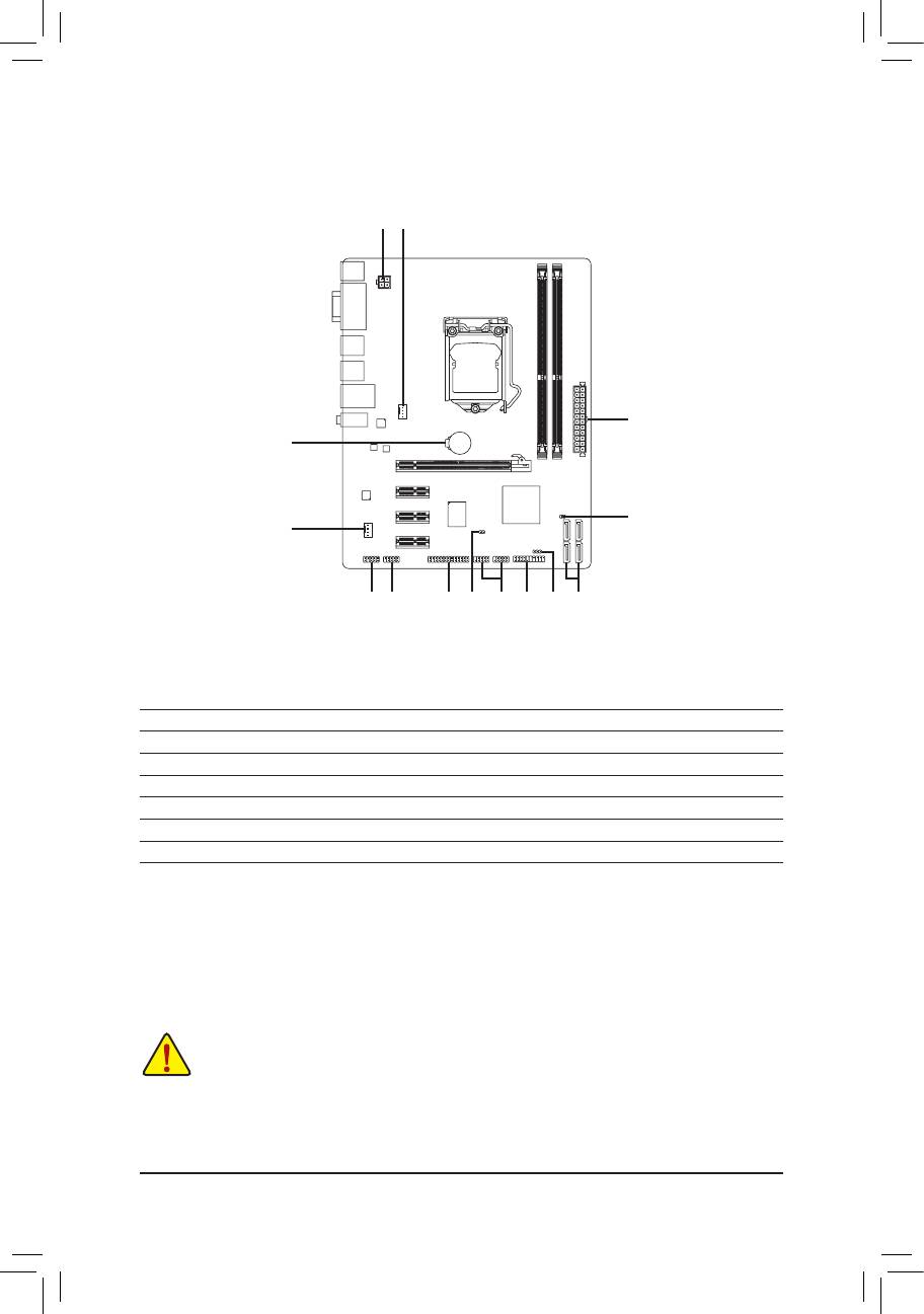
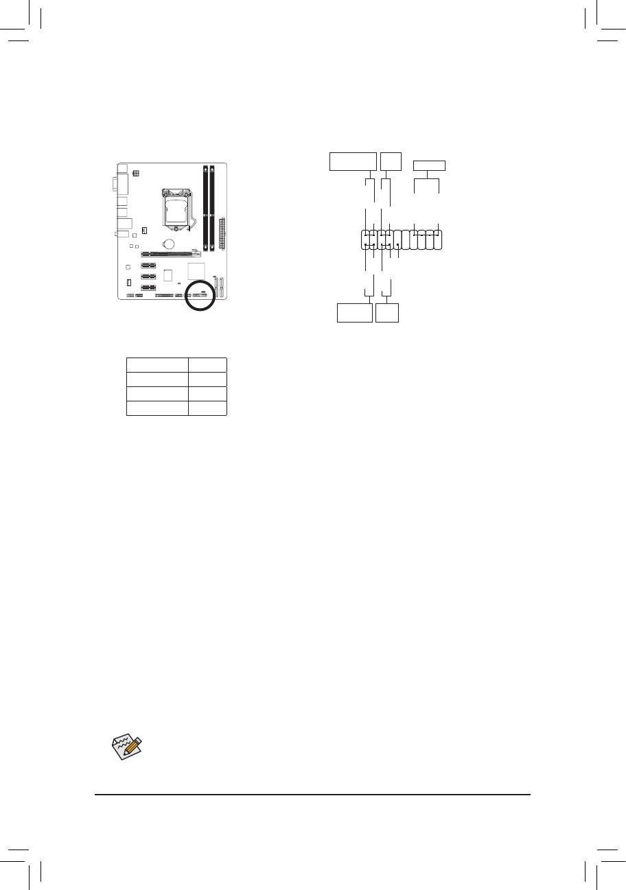
1-7 Internal Connectors
1
3
2
14
13
4
7 9 10
58 6 1211
1) ATX_12V
8) F_USB1/2
2) ATX
9) COMA
3) CPU_FAN
10) LPT
4) SYS_FAN
11) CI
5) SATA2_0/1/2/3
12) PWR_LED
6) F_PANEL
13) CLR_CMOS
7) F_AUDIO
14) BAT
Read the following guidelines before connecting external devices:
First make sure your devices are compliant with the connectors you wish to connect. •
Before installing the devices, be sure to turn off the devices and your computer. Unplug the •
power cord from the power outlet to prevent damage to the devices.
After installing the device and before turning on the computer, make sure the device cable has •
been securely attached to the connector on the motherboard.
Hardware Installation - 14 -
- 15 - Hardware Installation
G.QBOFM
DEBUG
PORT
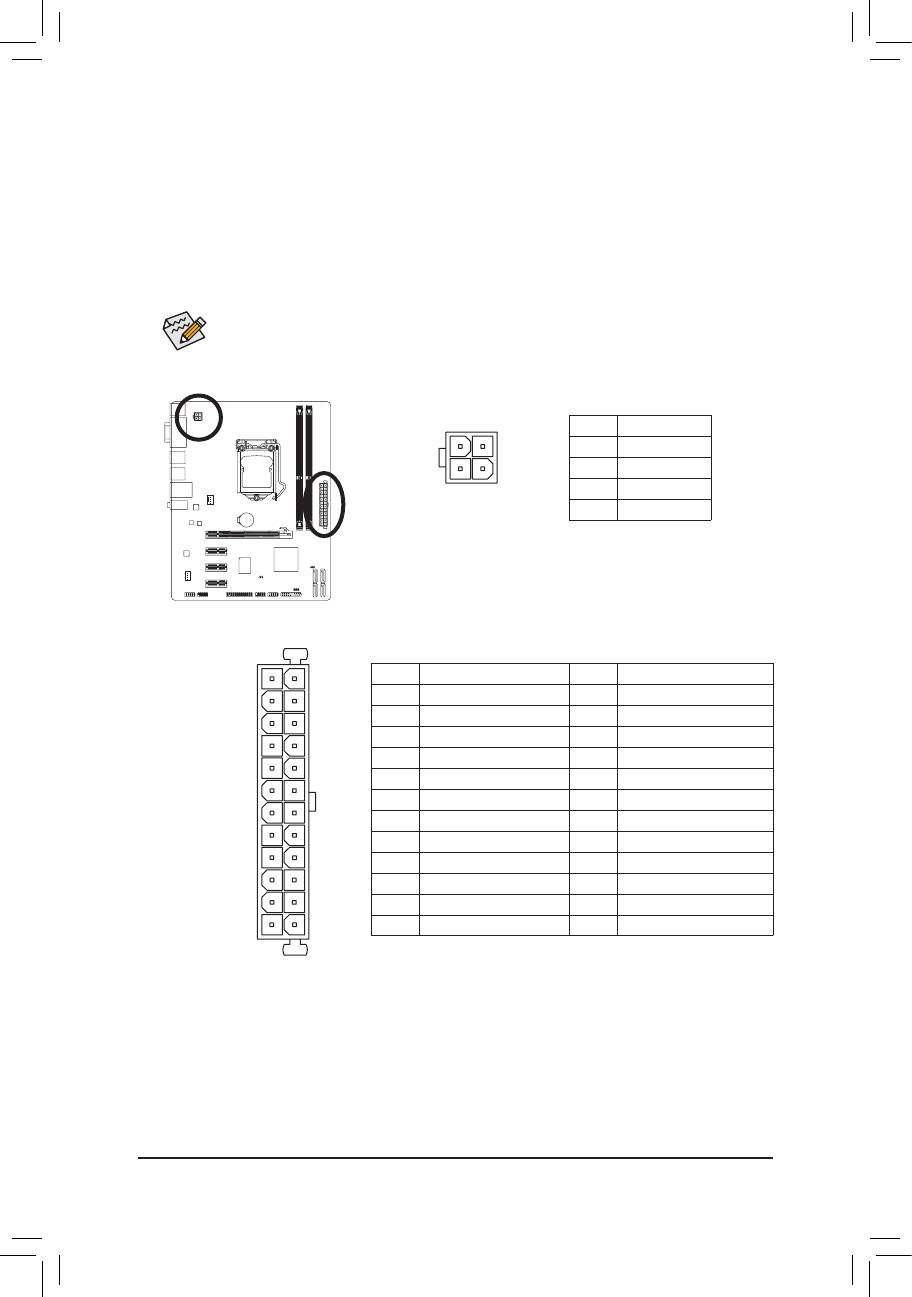
1/2) ATX_12V/ATX (2x2 12V Power Connector and 2x12 Main Power Connector)
With the use of the power connector, the power supply can supply enough stable power to all the com-
ponents on the motherboard. Before connecting the power connector, rst make sure the power supply
is turned off and all devices are properly installed. The power connector possesses a foolproof design.
Connect the power supply cable to the power connector in the correct orientation. The 12V power con-
nector mainly supplies power to the CPU. If the 12V power connector is not connected, the computer will
not start.
To meet expansion requirements, it is recommended that a power supply that can withstand high
power consumption be used (500W or greater). If a power supply is used that does not provide
the required power, the result can lead to an unstable or unbootable system.
ATX_12V:
4
2
Pin No. Denition
1 GND
2 GND
3
1
3 +12V
4 +12V
ATX_12V
ATX:
2412
Pin No. Denition Pin No. Denition
1 3.3V 13 3.3V
2 3.3V 14 -12V
3 GND 15 GND
4 +5V 16 PS_ON (soft On/Off)
5 GND 17 GND
6 +5V 18 GND
7 GND 19 GND
8 Power Good 20 -5V
9 5VSB (stand by +5V) 21 +5V
10 +12V 22 +5V
11 +12V (Only for 2x12-pin ATX) 23 +5V (Only for 2x12-pin ATX)
131
12 3.3V (Only for 2x12-pin ATX) 24 GND (Only for 2x12-pin ATX)
ATX
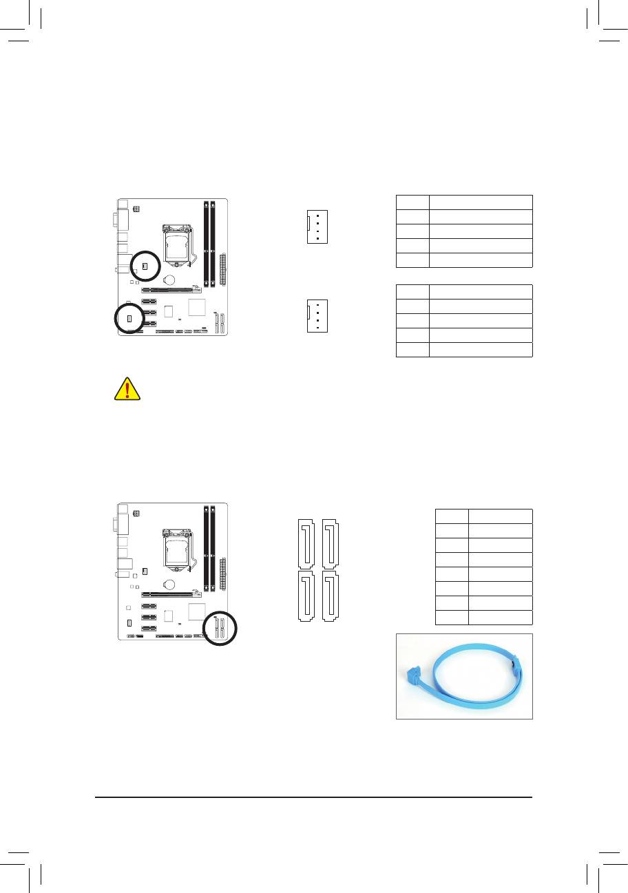
3/4) CPU_FAN/SYS_FAN (Fan Headers)
The motherboard has a 4-pin CPU fan header (CPU_FAN), a 4-pin system fan header (SYS_FAN). Most
fan headers possess a foolproof insertion design. When connecting a fan cable, be sure to connect it in
the correct orientation (the black connector wire is the ground wire). The motherboard supports CPU fan
speed control, which requires the use of a CPU fan with fan speed control design. For optimum heat dis-
sipation, it is recommended that a system fan be installed inside the chassis.
CPU_FAN:
Pin No. Denition
1 GND
2 +12V /Speed Control
3 Sense
CPU_FAN
4 Speed Control
SYS_FAN:
Pin No. Denition
1 GND
2 +12V /Speed Control
3 Sense
SYS_FAN
4 Reserve
Be sure to connect fan cables to the fan headers to prevent your CPU and system from overheating. Over- •
heating may result in damage to the CPU or the system may hang.
These fan headers are not conguration jumper blocks. Do not place a jumper cap on the headers. •
Hardware Installation - 16 -
G.QBOFM
DEBUG
PORT
G.QBOFM
DEBUG
PORT
1
1
5) SATA2_0/1/2/3 (SATA 3Gb/s Connectors)
The SATA connectors conform to SATA 3Gb/s standard and are compatible with SATA 1.5Gb/s standard.
Each SATA connector supports a single SATA device.
7
7
Pin No. Denition
1 GND
SATA2_0SATA2_1
2 TXP
3 TXN
4 GND
5 RXN
SATA2_2SATA2_3
6 RXP
7 GND
1
1
Please connect the L-shaped end of
the SATA cable to your SATA hard
drive.
G.QBOFM
DEBUG
PORT
G.QBOFM
DEBUG
PORT
G.QBOFM
DEBUG
PORT
G.QBOFM
DEBUG
PORT
6) F_PANEL (Front Panel Header)
Connect the power switch, reset switch, speaker, and system status indicator on the chassis to this
header according to the pin assignments below. Note the positive and negative pins before connecting
the cables.
Message/Power/
Sleep LED
Speaker
MSG+
PW+
MSG-
PW-
SPEAK+
SPEAK-
2
20
1
19
HD-
NC
RES+
HD+
RES-
Hard Drive
Reset
Activity LED
Switch
MSG • (Message/Power/Sleep LED):
System Status LED
Connects to the power status indicator on the chassis front panel. The LED
S0 On
is on when the system is operating. The LED keeps blinking when the sys-
S1 Blinking
tem is in S1 sleep state. The LED is off when the system is in S3/S4 sleep
S3/S4/S5 Off
state or powered off (S5).
PW • (Power Switch):
Connects to the power switch on the chassis front panel. You may congure the way to turn off your
system using the power switch (refer to Chapter 2, "BIOS Setup," "Power Management Setup," for
more information).
SPEAK • (Speaker):
Connects to the speaker on the chassis front panel. The system reports system startup status by is-
suing a beep code. One single short beep will be heard if no problem is detected at system startup. If
a problem is detected, the BIOS may issue beeps in different patterns to indicate the problem.
HD • (Hard Drive Activity LED)
Connects to the hard drive activity LED on the chassis front panel. The LED is on when the hard drive
is reading or writing data.
RES • (Reset Switch):
Connects to the reset switch on the chassis front panel. Press the reset switch to restart the computer
if the computer freezes and fails to perform a normal restart.
NC • :
No connection.
The front panel design may differ by chassis. A front panel module mainly consists of power
switch, reset switch, power LED, hard drive activity LED, speaker and etc. When connecting your
chassis front panel module to this header, make sure the wire assignments and the pin assign-
ments are matched correctly.
- 17 - Hardware Installation
F_USB30
F_PANEL(NH) F_PANEL
F_AUDIO(H)
DIP
BIOS Switcher (X58A-OC)
1
1
1
1
123
DIP
1 2 3
DIP
1 2 3
1 2 3
DIP
PCIe power connector (SATA)(X58A-OC)
Voltage measurement module(X58A-OC)
w/housing
TPM
(H61M-D2)
DB_PORT
PWM Switch (X58A-OC)
Power
Switch
7) F_AUDIO (Front Panel Audio Header)
The front panel audio header supports Intel High Denition audio (HD) and AC'97 audio. You may connect
your chassis front panel audio module to this header. Make sure the wire assignments of the module con-
nector match the pin assignments of the motherboard header. Incorrect connection between the module
connector and the motherboard header will make the device unable to work or even damage it.
For HD Front Panel Audio: For AC'97 Front Panel Audio:
Pin No. Denition
Pin No. Denition
1 MIC2_L
1 MIC
9
1
2 GND
2 GND
10
2
3 MIC2_R
3 MIC Power
4 -ACZ_DET
4 NC
5 LINE2_R
5 Line Out (R)
6 GND
6 NC
7 FAUDIO_JD
7 NC
8 No Pin
8 No Pin
9 LINE2_L
9 Line Out (L)
10 GND
10 NC
The front panel audio header supports HD audio by default. •
Audio signals will be present on both of the front and back panel audio connections simultane- •
ously.
Some chassis provide a front panel audio module that has separated connectors on each wire •
instead of a single plug. For information about connecting the front panel audio module that
has different wire assignments, please contact the chassis manufacturer.
8) F_USB1/2 (USB 2.0/1.1 Headers)
The headers conform to USB 2.0/1.1 specication. Each USB header can provide two USB ports via an
optional USB bracket. For purchasing the optional USB bracket, please contact the local dealer.
Pin No. Denition
1 Power (5V)
9
1
2 Power (5V)
10
2
3 USB DX-
4 USB DY-
5 USB DX+
6 USB DY+
7 GND
8 GND
9 No Pin
10 NC
Do not plug the IEEE 1394 bracket (2x5-pin) cable into the USB header. •
Prior to installing the USB bracket, be sure to turn off your computer and unplug the power •
cord from the power outlet to prevent damage to the USB bracket.
Hardware Installation - 18 -
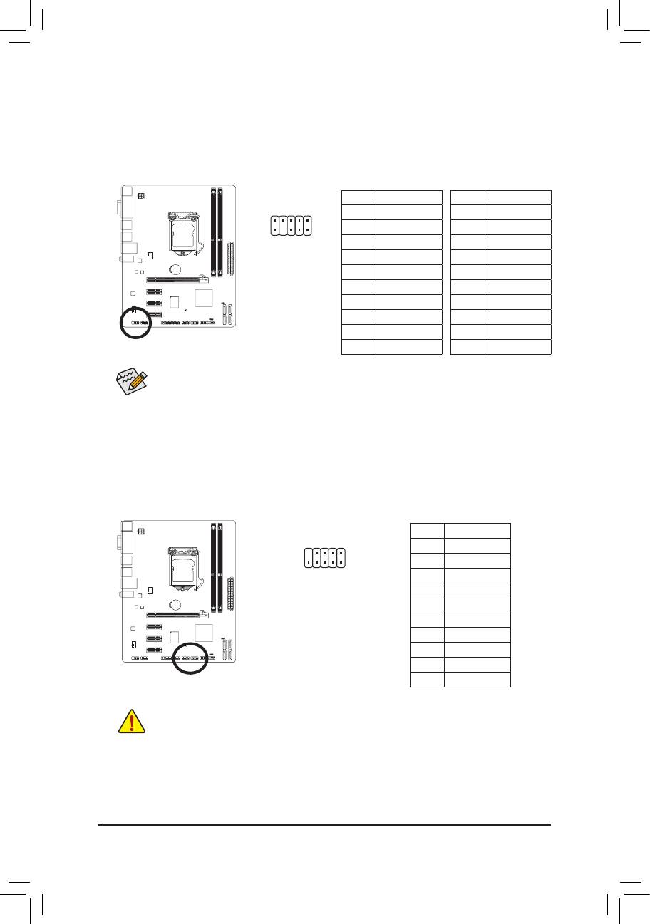
9) COMA (Serial Port Header)
The COM header can provide one serial port via an optional COM port cable. For purchasing the op-
tional COM port cable, please contact the local dealer.
Pin No. Denition
9
1
1 NDCD-
10
2
2 NSIN
3 NSOUT
4 NDTR-
5 GND
6 NDSR-
7 NRTS-
8 NCTS-
9 NRI-
10 No Pin
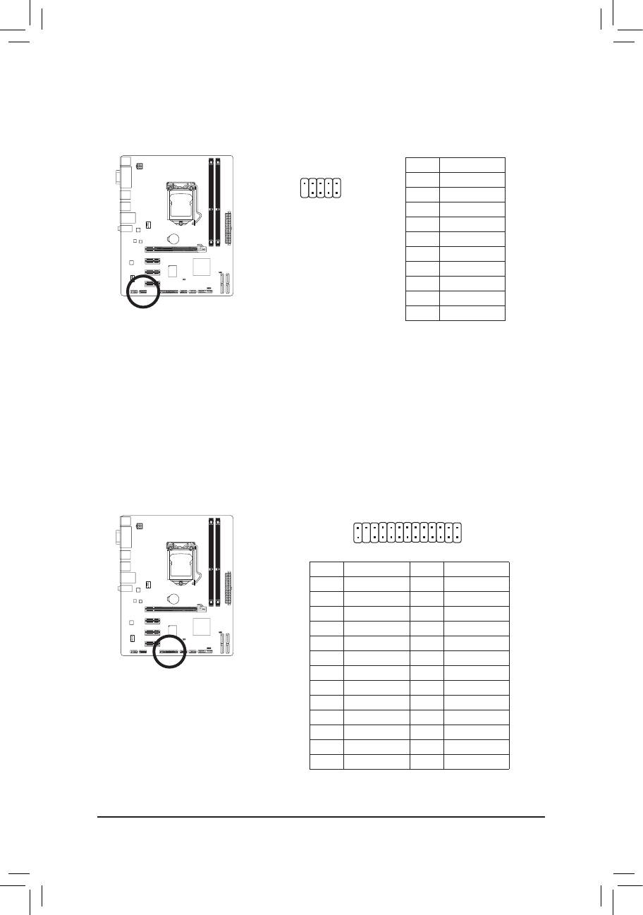
10) LPT (Parallel Port Header)
The LPT header can provide one parallel port via an optional LPT port cable. For purchasing the optional
LPT port cable, please contact the local dealer.
25
1
26
2
Pin No. Denition Pin No. Denition
1 STB- 14 GND
2 AFD- 15 PD6
3 PD0 16 GND
4 ERR- 17 PD7
5 PD1 18 GND
6 INIT- 19 ACK-
7 PD2 20 GND
8 SLIN- 21 BUSY
9 PD3 22 GND
10 GND 23 PE
11 PD4 24 No Pin
12 GND 25 SLCT
13 PD5 26 GND
- 19 - Hardware Installation
G.QBOFM
DEBUG
PORT
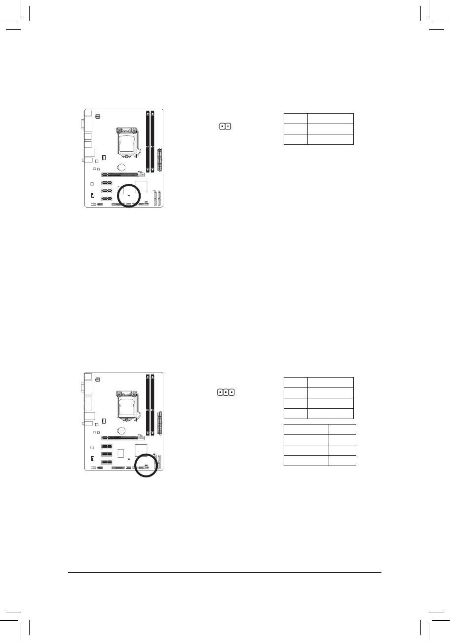
11) CI (Chassis Intrusion Header)
This motherboard provides a chassis detection feature that detects if the chassis cover has been re-
moved. This function requires a chassis with chassis intrusion detection design.
Pin No. Denition
1
1 Signal
2 GND
12) PWR_LED (System Power LED Header)
This header can be used to connect a system power LED on the chassis to indicate system power
status. The LED is on when the system is operating. The LED keeps blinking when the system is in S1
sleep state. The LED is off when the system is in S3/S4 sleep state or powered off (S5).
Pin No. Denition
1
1 MPD+
2 MPD-
3 MPD-
System Status LED
S0 On
S1 Blinking
S3/S4/S5 Off
Hardware Installation - 20 -
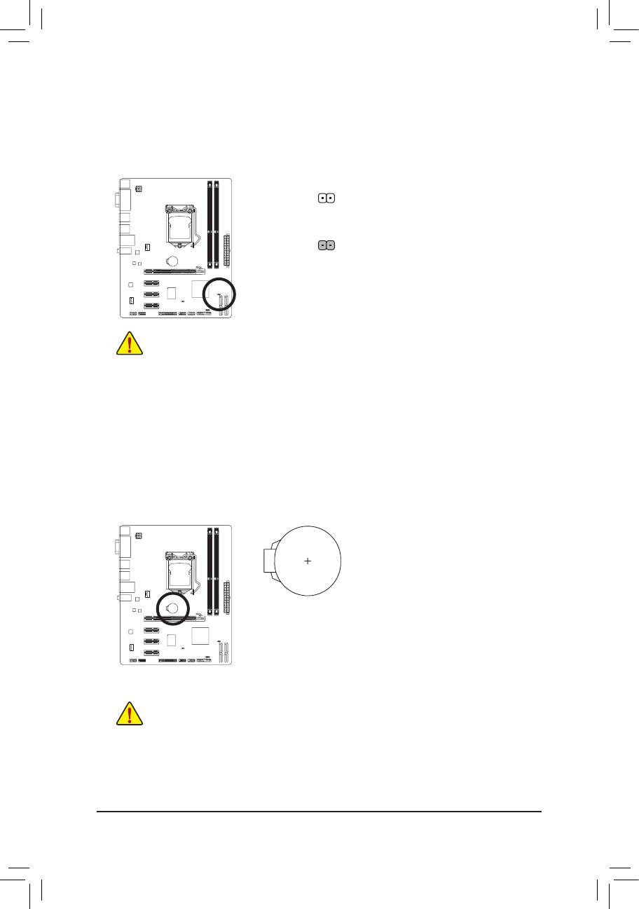
13) CLR_CMOS (Clearing CMOS Jumper)
Use this jumper to clear the CMOS values (e.g. date information and BIOS congurations) and reset
the CMOS values to factory defaults. To clear the CMOS values, place a jumper cap on the two pins to
temporarily short the two pins or use a metal object like a screwdriver to touch the two pins for a few
seconds.
Open: Normal
Short: Clear CMOS Values
Always turn off your computer and unplug the power cord from the power outlet before clear- •
ing the CMOS values.
After clearing the CMOS values and before turning on your computer, be sure to remove the •
jumper cap from the jumper. Failure to do so may cause damage to the motherboard.
After system restart, go to BIOS Setup to load factory defaults (select Load Optimized De- •
faults) or manually congure the BIOS settings (refer to Chapter 2, "BIOS Setup," for BIOS
congurations).
14) BAT (Battery)
The battery provides power to keep the values (such as BIOS congurations, date, and time information)
in the CMOS when the computer is turned off. Replace the battery when the battery voltage drops to a
low level, or the CMOS values may not be accurate or may be lost.
You may clear the CMOS values by removing the battery:
Turn off your computer and unplug the power cord.1.
Gently remove the battery from the battery holder and wait for one minute. 2.
(Or use a metal object like a screwdriver to touch the positive and negative
terminals of the battery holder, making them short for 5 seconds.)
Replace the battery. 3.
Plug in the power cord and restart your computer.4.
Always turn off your computer and unplug the power cord before replacing the battery. •
Replace the battery with an equivalent one. Danger of explosion if the battery is replaced with •
an incorrect model.
Contact the place of purchase or local dealer if you are not able to replace the battery by your- •
self or uncertain about the battery model.
When installing the battery, note the orientation of the positive side (+) and the negative side (-) •
of the battery (the positive side should face up).
Used batteries must be handled in accordance with local environmental regulations. •
- 21 - Hardware Installation


