Gigabyte GA-945GCM-S2C: Chapter 5 Appendix
Chapter 5 Appendix: Gigabyte GA-945GCM-S2C
Chapter 5 Appendix
5-1 Configuring Audio Input and Output
5-1-1 Configuring 2/4/5.1-Channel Audio
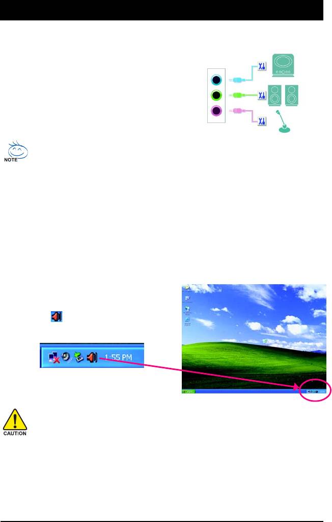
The motherboard provides three audio jacks on the back
(Note)
Line In
panel which support 2/4/5.1-channel
audio. The picture
to the right shows the default audio jack assignments.
Front Speaker Out
Mic In
Audio signals will be present on both of the front and back panel audio connections simultaneously.
If you want to mute the back panel audio (only supported when using an HD front panel audio
module), refer to instructions on page 71.
High Definition Audio (HD Audio)
HD Audio includes multiple high quality digital-to-analog converters (DACs) that support 44.1KHz/
48KHz/ 96KHz sampling rate. HD Audio features multistreaming capabilities that allow multiple audio
streams (in and out) to be simultaneously processed. For example, users can listen to MP3 music,
have an Internet chat, make a telephone call over the Internet, and etc. all at the same time.
A. Configuring Speakers:
(The following instructions use Windows XP as the example operating system.)
Step 1:
After installing the audio driver, the Audio
Manager icon will appear in your system tray.
Double-click the icon to access the Audio Control
Panel.
Before installing the audio driver, make sure the "Microsoft UAA Bus driver for High Definition
Audio" has been installed from the motherboard driver disk and your operating system has
been updated with the latest Service Pack for Windows.
(Note) 2/4/5.1 Channel Audio Configurations:
Refer to the following for multi-channel speaker configurations.
• 2 channel audio: Headphone or Line out.
• 4 channel audio: Front speaker out and Rear speaker out.
• 5.1 channel audio: Front speaker out, Rear speaker out, and Center/Subwoofer speaker out.
Appendix- 69 -
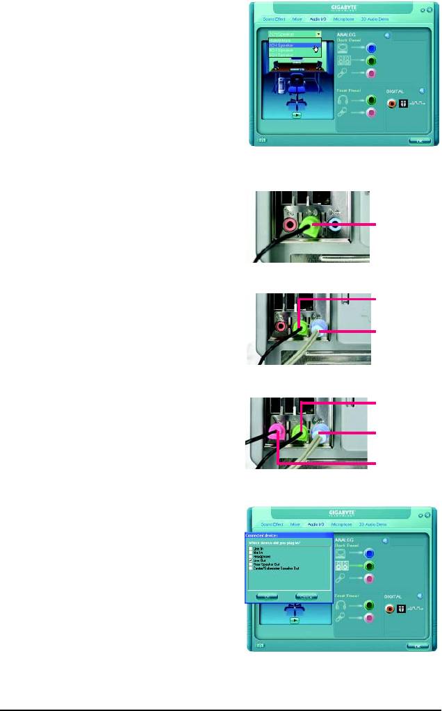
Step 2:
Click the Audio I/O tab. In the speaker list on the
left, select 2CH Speaker, 4CH Speaker, or 6CH
Speaker according to the type of speaker configura-
tion you wish to set up.
Step 3:
The pictures to the right show the 2-, 4-, 5.1-channel
2-Channel Speakers:
speaker configurations.
Speakers or
Headphones
4-Channel Speakers:
Front Speaker Out
Rear Speaker Out
5.1-Channel Speakers:
Front Speaker Out
Rear Speaker Out
Center/Subwoofer
Speaker Out
Step 4:
Everytime you connect an audio device to an audio
jack, the Connected device box appears. Select
the device according to the type of device you connect.
Then click OK to complete the configuration.
GA-945GCM-S2L/S2C Motherboard - 70 -
B. Configuring Sound Effect:
You may configure an audio environment on the Sound Effect tab.
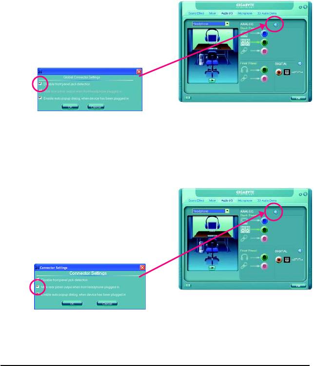
C. Activating an AC'97 Front Panel Audio Module:
If your chassis provides an AC'97 front panel audio
module, to activate the AC'97 functionality, click the
tool icon on the Audio I/O tab. On the Connector
Settings box, select the Disable front panel jack
detection check box. Click OK to complete.
D. Muting the Back Panel Audio (For HD Audio Only):
Click the tool icon on the Audio I/O tab. On the
Connector Settings box, select the Mute rear
panel output when front headphone plugged
in check box. Click OK to complete.
Appendix- 71 -
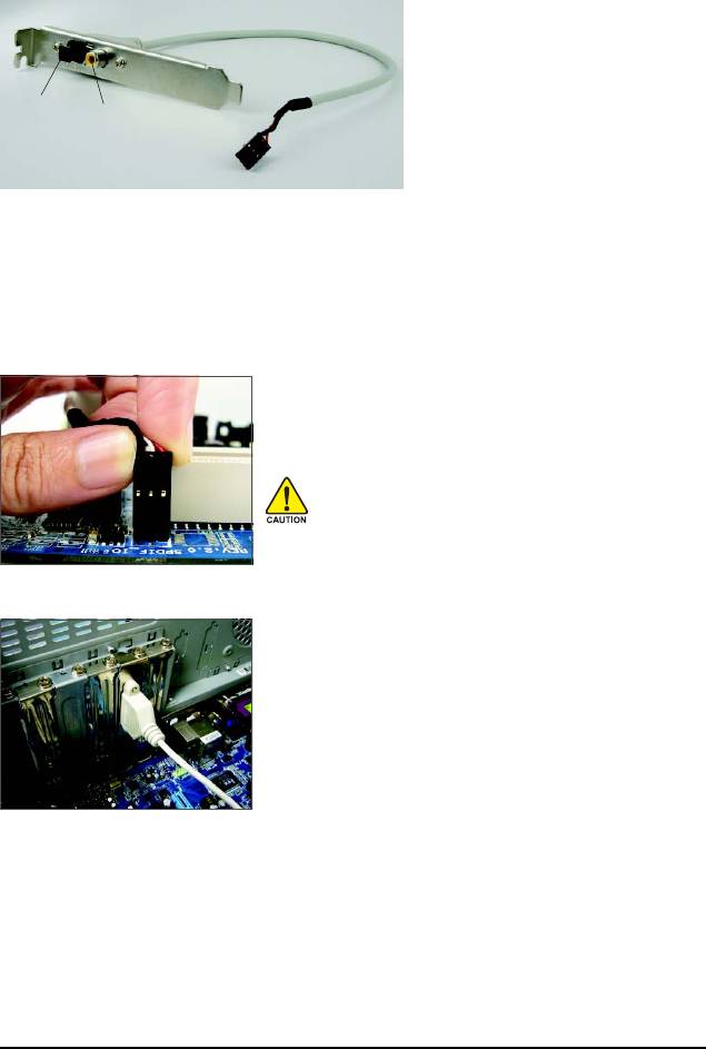
5-1-2 Installing the S/PDIFOut Cable (Optional)
The S/PDIF out cable provides S/PDIF out functionalities.
Optical
Coaxial
S/PDIF Out
S/PDIFOut
S/PDIF out:
The S/PDIF out jacks can transmit audio signals to an external decoder for decoding to get the best
audio quality. Install the S/PDIF in and out cable first if you want to output S/PDIF digital audio signals
to an external decoder.
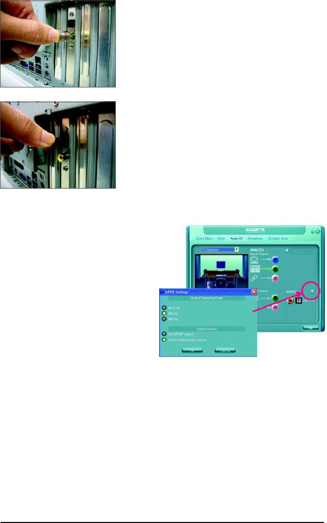
A. Installing the S/PDIF Out Cable:
Step 1:
First, attach the connector at the end of the cable to the SPDIF_O
header on your motherboard.
Pin 1 (the red wire) of the S/PDIF out cable must align
with pin 1 of the SPDIF_O header. Incorrect connection
may render the device unusable or even result in
damage to the device.
Step 2:
Secure the metal bracket to the chassis back panel with a
screw.
GA-945GCM-S2L/S2C Motherboard - 72 -
Step 3:
Connect a S/PDIF coaxial cable or a S/PDIF optical cable (either
one) to an external decoder for transmitting the S/PDIF digital
audio signals.
S/PDIF Coaxial Cable
S/PDIF Optical Cable
B. Configuring S/PDIF out:
Click the tool icon in the DIGITAL section. In the
S/PDIF Settings dialog box, select an output sam-
pling rate and select (or disable) the output source.
Click OK to complete the configuration.
Appendix- 73 -
5-1-3 Configuring Microphone Recording
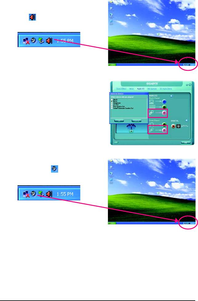
Step 1:
After installing the audio driver, the Audio
Manager icon will appear in your system tray.
Double-click the icon to access the Audio Control
Panel.
Step 2:
Connect your microphone to the Mic in jack (pink)
on the back panel or the Line in jack on the front
panel. Then configure the jack for microphone
functionality.
Note: The microphone functions on the front panel
and back panel cannot be used at the same time.
Step 3:
Locate the Volume icon in your system tray
and click it to open the volume control panel
GA-945GCM-S2L/S2C Motherboard - 74 -
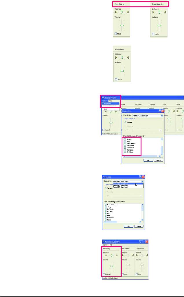
Step 4:
To hear the sound being recorded during the record-
ing process when using the microphone function on
or
the front panel, do not select the Mute check box
under Front Pink In or Front Green In in Master
Volume. It is recommended that you set the volume
at a middle level.
To hear the sound being recorded during the record-
ing process when using the microphone function on
the back panel, do not select the Mute check box
under Mic Volume in Master Volume. It is recom-
mended that you set the volume at its middle level.
(Note)
If you cannot find the volume control options you
need in Master Volume, go to the Options menu
and then choose Properties. Select the volume con-
trol options you wish to show and click OK to
complete.
Step 5:
Next, while in Master Volume, go to Options and
click Properties. In the Mixer device list, select
Realtek HD Audio Input. Then set the recording
sound level properly. Do NOT mute the recording
sound, or you will not hear any sound when playing
back the recording you just made.
Select Realtek HD Audio Input in the Mixer device list
Recording Control
Appendix- 75 -
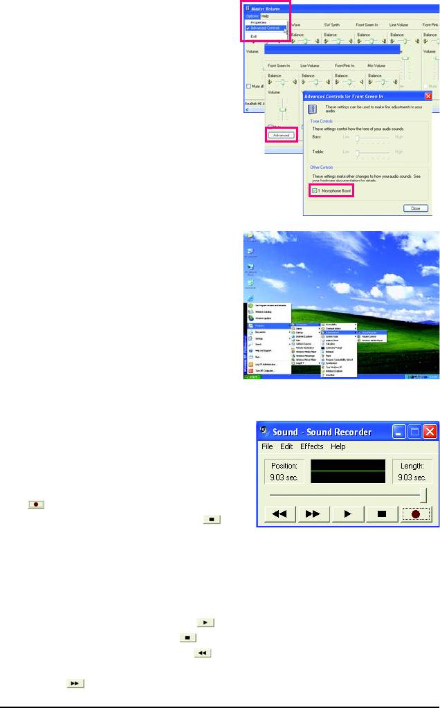
Step 6:
To raise the recording and playing sound for the
microphone, go to Options in Master Volume and
select Advanced Controls. Click the Advanced
button under a volume control option (e.g. Front Green
In, Front Pink In). In the Other Controls field, select
the 1 Microphone Boost check box.
Step 7:
After completion, click Start, point to Programs,
point to Accessories, point to Entertainment, and
then click Sound Recorder to begin the sound
recording.
5-1-4 Using the Sound Recorder
Recording the Sound:
1. Make sure you have connected the audio input
device (e.g. microphone) to the computer.
2. On the File menu, choose New.
3. To record a sound file, click the Recording but-
ton .
4. To stop the recording, click the Stop button .
Be sure to save the recording upon completion.
Playing the Sound:
1. On the File menu, choose Open.
2. In the Open dialog box, select the sound (.wav)
file you wish to play.
3. To play a sound file, click the Play button .
4. To stop playing, click the Stop button .
5. You may use the Fast Forward button to
move to the beginning of a file orthe Fast Back-
ward button to the end.
GA-945GCM-S2L/S2C Motherboard - 76 -

5-2 Troubleshooting
5-2-1 Frequently Asked Questions
To read more FAQs for your motherboard, please go to the Support\Motherboard\FAQ page on
GIGABYTE's website.
Q:In the BIOS Setup program, why are some BIOS options missing?
A: Some advanced options are hidden in the BIOS Setup program. Press <Delete> to enter BIOS Setup
during the POST. In the Main Menu, press <Ctrl>+<F1> to show the advanced options.
Q:Why is the light of my keyboard/optical mouse still on after the computer shuts down?
A:Some motherboard provides a small amount of standby power after the computer shuts down and
that's why the light is still on.
Q:How do I clear the CMOS values?
A: If your motherboard has a clearing CMOS jumper, refer to the instructions on the CLR_CMOS jumper
in Chapter 1 to short the jumper to clear the CMOS values. If your board doesn't have this jumper,
refer to the instructions on the motherboard battery in Chapter 1. You can temporarily remove the
battery from the battery holder to stop supplying power to the CMOS, which will clear the CMOS
values after about one minute. Refer to the steps below:
Steps:
1. Turn off your computer and unplug the power cord.
2. Gently remove the battery from the battery holder and wait for one minute.
(Or use a metal object like a screwdriver to touch the positive and negative terminals of the battery
holder, making them short for 5 seconds.)
3. Replace the battery.
4. Plug in the power cord and restart your computer.
5. Press <Delete> to enter BIOS Setup. Select "Load Fail-Safe Defaults" (or "Load Optimized Defaults")
to load BIOS default settings.
6. Saves changes and exit BIOS Setup (select "Save & Exit Setup") to restart your computer.
Q:Why do I still get a weak sound even though I have turned my speaker to the maximum volume?
A: Make sure your speaker is equipped with an internal amplifier. If not, try a speaker with power/
amplifier.
Q:What do the beeps emitted during the POST mean?
A: The following Award BIOS beep code descriptions may help you identify possible computer problems.
(For reference only.)
1 short: System boots successfully
2 short: CMOS setting error
1 long, 1 short: Memory or motherboard error
1 long, 2 short: Monitor or graphics card error
1 long, 3 short: Keyboard error
1 long, 9 short: BIOS ROM error
Continuous long beeps: Graphics card not inserted properly
Continuous short beeps: Power error
Appendix- 77 -
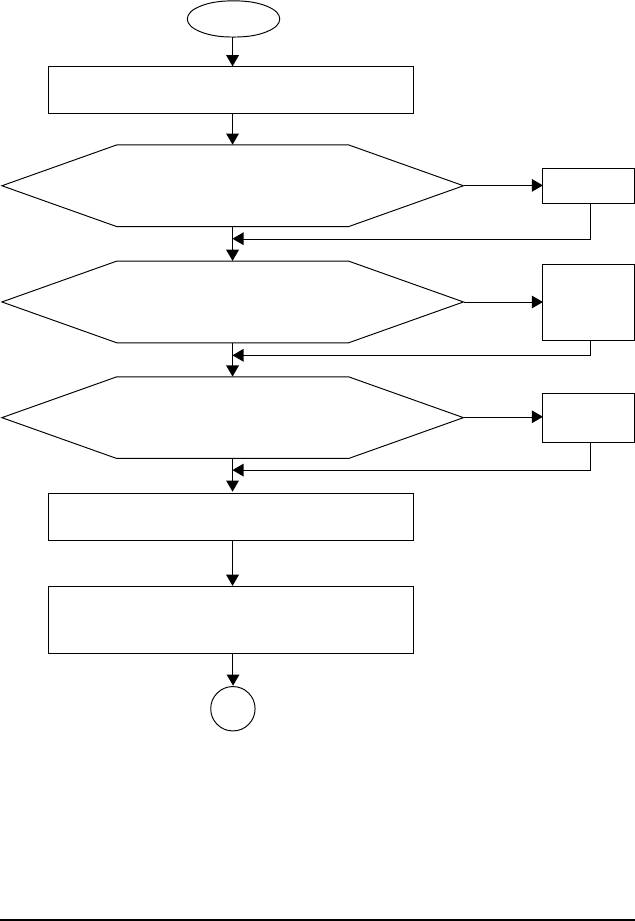
5-2-2 Troubleshooting Procedure
If you encounter any troubles during system startup, follow the troubleshooting procedure below to
solve the problem.
START
Turn off the power. Remove all peripherals, connecting cables, and
power cord etc.
Make sure the motherboard does not short-circuit with the chassis
Ye s
Isolate the short
circuit.
or other metal objects.
No
The problem is verified and solved.
Secure the CPU
Check if the CPU cooler is attached to the CPU securely. Is the
cooler on the CPU.
No
power connector of the CPU cooler connected to the CPU_FAN
Connect the CPU
cooler power cable
header properly?
to the motherboard.
Ye s
The problem is verified and solved.
Correctly insert the
No
Check if the memory is installed properly on the memory slot.
memory into the
memory socket.
Ye s
The problem is verified and solved.
Insert the graphics card. Connect the ATX main power cable and the 12V
power cable. Turn on the power to start the computer.
Press <Delete> to enter BIOS Setup. Select "Load Fail-Safe Defaults"
(or "Load Optimized Defaults"). Select "Save & Exit Setup" to save
changes and exit BIOS Setup.
A
(Continued...)
GA-945GCM-S2L/S2C Motherboard - 78 -
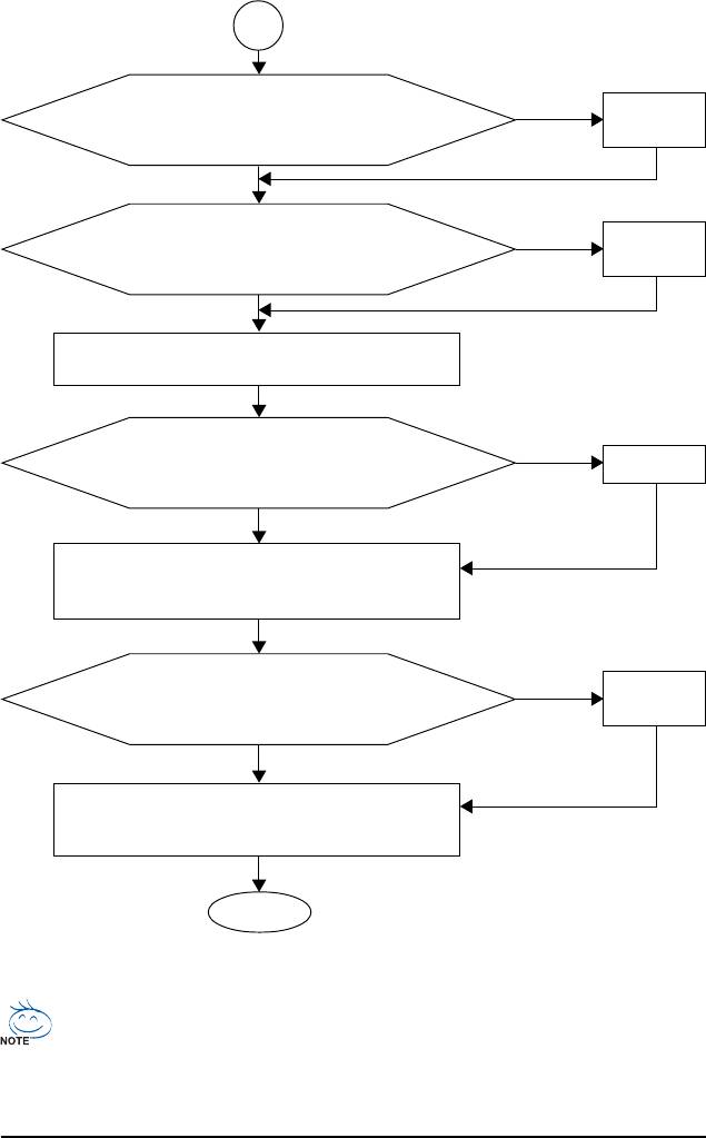
A
The power supply,
When the computer is turned on, is the CPU cooler running?
No
CPU or CPU socket
might fail.
Ye s
The problem is verified and solved.
The graphics card,
No
Check if there is display on your monitor.
expansion slot, or
monitor might fail.
Ye s
The problem is verified and solved.
Turn off the computer. Plugg in the keyboard and mouse and restart the
computer.
No
The keyboard or
Check if the keyboard is working properly.
mouse might fail.
Ye s
Press <Delete> to enter BIOS Setup. Select "Load Fail-Safe Defaults"
(or "Load Optimized Defaults"). Select "Save & Exit Setup" to save
The problem is verified and solved.
changes and exit BIOS Setup.
The IDE/SATA
Turn off the computer and connect the IDE/SATA devices.
No
device, connector,
Check if the system can boot successfully.
or cable might fail.
Ye s
Reinstall the operating system. Reinstall other devices one by one (install
one device at one time and then boot the system to see if the device
The problem is verified and solved.
works successfully).
END
If the procedure above is unable to solve your problem, contact the place of purchase or local
dealer for help. Or go to the Support\Technical Service Zone page to submit your question. Our
customer service staff will reply you as soon as possible.
Appendix- 79 -


