Gigabyte GA-8VM800PMD-775: Chapter 4 Appendix
Chapter 4 Appendix: Gigabyte GA-8VM800PMD-775

English
Chapter 4 Appendix
4-1 Unique Software Utilities
(Not all model support these Unique Software Utilities, please check your MB features.)
U-PLUS D.P.S. (Universal Plus Dual Power System)
The U-Plus Dual Power System (U-Plus DPS) is a revolutionary eight-phase power circuit
built for ultimate system protection. Designed to withstand varying current levels and
changes, the U-Plus D.P.S. provides an immensely durable and stable power circuit to the
CPU for solid system stability. These characteristics make it the ideal companion with the
®
®
®
latest LGA775 Intel
Pentium
4 Processor as well as future Intel
processors. As well, 4
blue LED's are mounted on the U-Plus D.P.S. for intelligent indication of system loading.
M.I.T. (Motherboard Intelligent Tweaker)
Motherboard Intelligent Tweaker (M.I.T.) allows user to access and change BIOS feature
settings with relative speed and ease. Through GIGABYTE M.I.T. feature the user is no
longer required to switch into different modes within BIOS setup in order to change system
settings such as the CPU system bus, memory timings or to enabled Gigabyte's unique
C.I.A. 2 and M.I.B. 2 features. M.I.T.'s integration of all platform performance settings into
a single mode now gives any user the ability to control and enhance their computer system
to the desired level.
C.I.A.2 (CPU Intelligent Accelerator 2)
GIGABYTE CPU Intelligent Accelerator 2(C.I.A. 2) is designed to automatically adjust CPU
computing power to maximize system performance. When enabled, the program detects
the current CPU loading and automatically accelerates the CPU computing performance to
allow for a faster and smoother execution of programs. When the function is disabled, the
CPU is returned to its initial status.
M.I.B.2 (Memory Intelligent Booster 2)
Built on the original M.I.B., the new Memory Intelligent Booster 2 (M.I.B. 2) is designed
especially to maximize memory performance and boost memory bandwidth up to 10%.
With added branded memory module information, users are able to optimize memory
performance by selecting from a recommended memory module list.
S.O.S. (System Overclock Saver)
System Overclock Saver (S.O.S.) is a unique feature that eliminates system boot-up errors
resulting from system over-enhancement by the user. With GIGABYTE's proprietary
S.O.S. feature, users no longer need to open up the PC chassis and short-circuit the "Clear
CMOS" pins or the battery on the motherboard to reset the system back to factory default
settings. Instead, S.O.S. automatically resets the overclocked system settings back to their
factory defaults to provide a more user-friendly and reliable platform for users.
Download Center
Download Center allows users to quickly download and update their BIOS as well as the
latest drivers for their system. Download Center automatically runs a system check of the
user PC and provides the user with the current system information as well as displaying a
detailed list of all new drivers with the option for download.
C.O.M. (Corporate Online Management)
A web-based system management tool that allows system hardware information such as
CPU, memory, graphics card, etc. to be monitored and controlled via the Internet, C.O.M.
allows corporate MIS engineers to easily maintain corporate computers such as providing
the most up-to-date drivers and BIOS. (Do not use C.O.M. and @BIOS at the same time.)
Appendix- 51 -
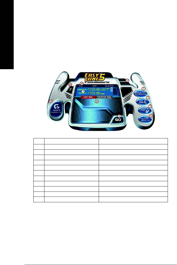
4-1-1 EasyTune 5 Introduction
EasyTune 5 presents the most convenient Windows based system performance enhancement and
manageability utility. Featuring several powerful yet easy to use tools such as 1) Overclocking for enhancing
English
system performance, 2) C.I.A. and M.I.B. for special enhancement for CPU and Memory, 3) Smart-Fan
control for managing fan speed control of both CPU cooling fan and North-Bridge Chipset cooling fan, 4) PC
(Note)
health for monitoring system status.
User Interface Overview
Button / Display Description
1. Overclocking Enters the Overclocking setting page
2. C.I.A./C.I.A.2 and M.I.B./M.I.B.2 Enters the C.I.A./2 and M.I.B./2 setting page
3. Smart-Fan Enters the Smart-Fan setting page
4. PC Health Enters the PC Health setting page
5. GO Confirmation and Execution button
6. "Easy Mode" & "Advance Mode" Toggles between Easy and Advance Mode
7. Display screen Display panel of CPU frequency
8. Function display LEDs Shows the current functions status
9. GIGABYTE Logo Log on to GIGABYTE website
TM
10. Help button Display EasyTune
5 Help file
TM
11. Exit or Minimize button Quit or Minimize EasyTune
5 software
(Note) EasyTune 5 functions may vary depending on different motherboards.
GA-8VM800PMD-775 Motherboard - 52 -
English
4-1-2 Xpress Recovery Introduction
What is Xpress Recovery ?
Xpress Recovery is a utility used to back up and restore an OS partition.
If the hard drive is not working properly, the user can restore the drive to
its original state.
1. Supports FAT16, FAT32, and NTFS formats
2. Must be connected to the IDE1 Master
3. Allows installation of only one OS
4. Must be used with an IDE hard disk supporting HPA
5. The first partition must be set as the boot partition. When the boot partition is backed up,
please do not alter its size.
6. Xpress Recovery is recommended when using Ghost to return boot manager to NTFS
format.
How to use the Xpress Recovery
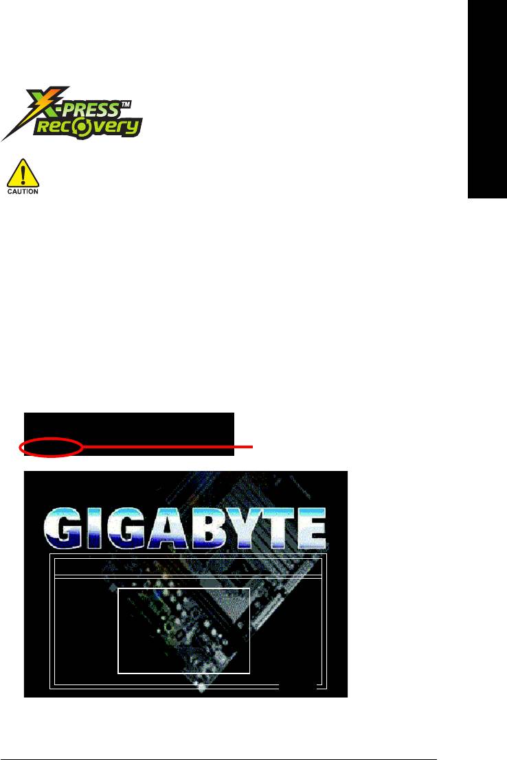
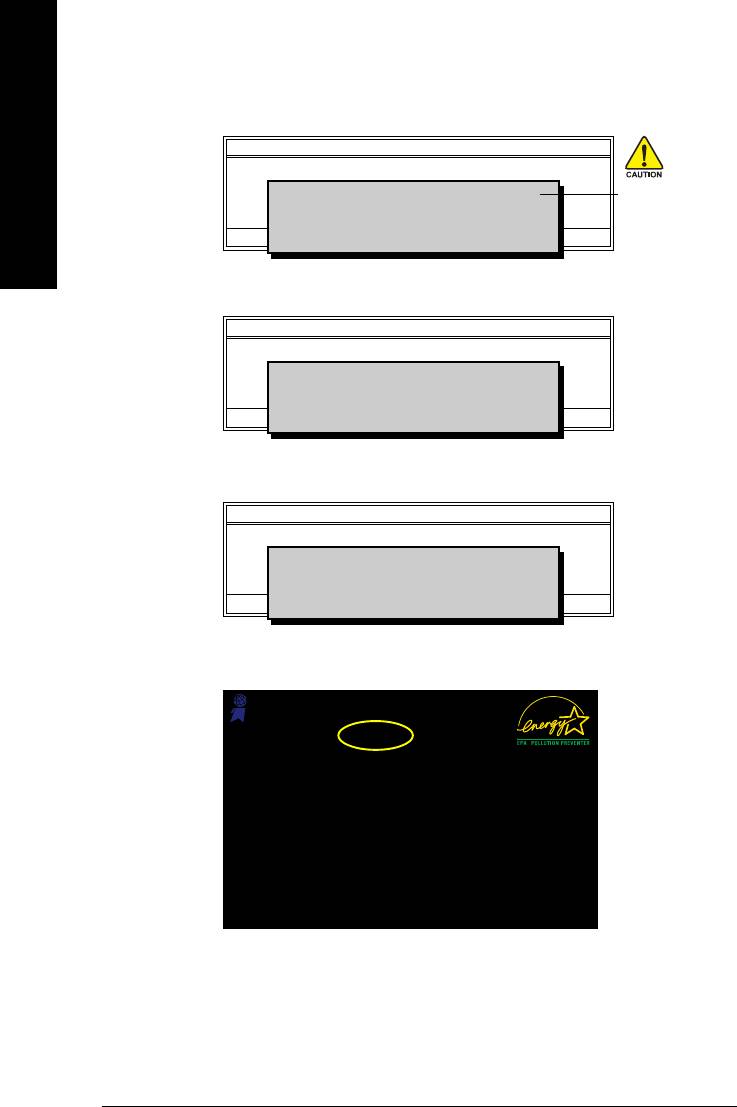
1. Boot from CD-ROM (BMP Mode)
Enter the BIOS menu, select "Advanced BIOS Feature" and set to boot from CD-ROM. Insert the
provided driver CD into your CD drive, then save and exit the BIOS menu. Once the computer has
restarted, the phrase "Boot from CD:" will appear at the bottom left-hand corner of the screen. When
"Boot from CD:" appears, press any key to enter Xpress Recovery.
Once you have completed this step, subsequent access to Xpress Recovery can also function by
pressing the F9 key during computer power on.
.
.
Verifying DMI Pool Data
Boot from CD:
Boot from CD:
Xpress Recovery V1.0 (C) Copy Right 2003. GIGABYTE Technology CO. , Ltd.
1. Execute Backup Utility
2. Execute Restore Utility
3. Remove Backup Image
4. Set Password
5. Exit and Restart
Build 2011
Appendix- 53 -
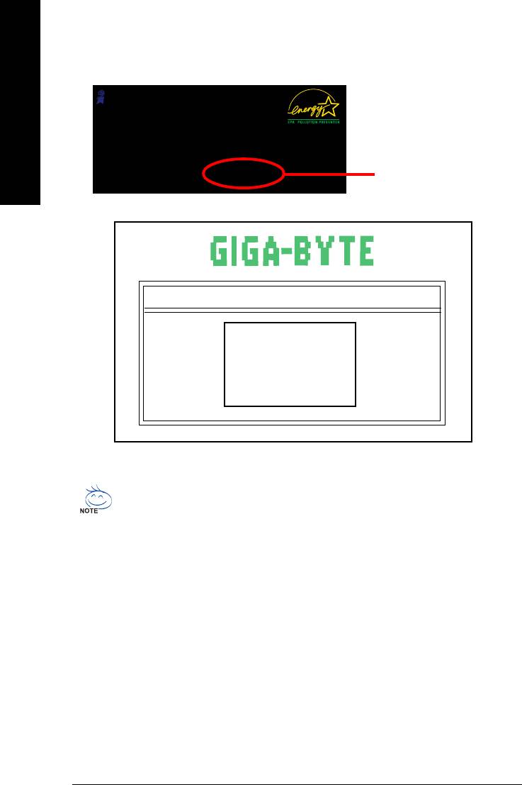
2. Press F9 during powering on the computer. (Text Mode)
Award Modular BIOS v6.00PG, An Energy Star Ally
Copyright (C) 1984-2004, Award Software, Inc.
Intel 865PE AGPSet BIOS for 8IPE1000MT F1
English
Check System Health OK
.
.
.
Press DEL to enter SETUP / Q-Flash, F9 For Xpress Recovery
F9 For Xpress Recovery
08/16/2002-I845GE-6A69YG01C-00
Xpress Recovery V1.0 (C) Copy Right 2003. GIGABYTE Technology CO. , Ltd.
1. Execute Backup Utility
2. Execute Restore Utility
3. Remove Backup Image
4. Set Password
5. Exit and Restart
1. If you have already entered Xpress Recovery by booting from the CD-ROM, you can
enter Xpress Recovery in the future by pressing the F9 key.
2. System storage capacity as well as drive reading/writing speed will affect backup speed.
3. It is recommended that Xpress Recovery be immediately installed after OS and all
required driver and software installations are complete.
GA-8VM800PMD-775 Motherboard - 54 -

1. Execute Backup Utility:
English
Press B to Backup your System or Esc to Exit
The backup utility will automatically scan your system and back up data as a backup image in your hard
drive.
Not all systems support access to Xpress Recovery by pressing the F9 key during computer
power on. If this is the case, please use the boot from CD-ROM method to enter Xpress
Recovery.
2. Execute Restore Utility:
This program will recover your system to factory default.
Press R to restore your system back to factory default or press Esc to exit
Restores backup image to original state.
3. Remove Backup Image:
Remove backup image. Are you sure? (Y/N)
Remove the backup image.
4. Set Password:
Please input a 4-16 character long password (a-z or 0-9) or press Esc to exit
You can set a password to enter Xpress Recovery to protect your hard disk data. Once this is done,
password input will be required to enter Xpress Recovery during the next as well as subsequent system
restarts. If you wish to remove the need for password entry, please select "Set Password" and under
"New Password/Confirm Password", make sure there is no entry and then press "Enter" to remove
password requirement.
5. Exit and Restart:
Exit and restart your computer.
Appendix- 55 -

4-1-3 Flash BIOS Method Introduction
TM
Method 1 : Q-Flash
Utility
TM
Q-Flash
is a BIOS flash utility embedded in Flash ROM. With this utility,
English
users only have to stay in the BIOS menu when they want to update
BIOS. Q-Flash?allows users to flash BIOS without any utility in DOS or
TM
Windows. Using Q-Flash
indicating no more fooling around with any complicated instructions and
operating system since it is in the BIOS menu.
Please note that because updating BIOS has potential risk, please do it with caution!! We are
sorry that Gigabyte Technology Co., Ltd is not responsible for damages of system because of
incorrect manipulation of updating BIOS to avoid any claims from end-users.
Before You Begin:
TM
Before you start updating BIOS with the Q-Flash
utility, please follow the steps below first.
1. Download the latest BIOS for your motherboard from Gigabyte's website.
2. Extract the BIOS file downloaded and save the BIOS file (the one with model name.Fxx. For
example, 8KNXPU.Fba) to a floppy disk.
3. Reboot your PC and press Del to enter BIOS menu.
The BIOS upgrading guides below are separated into two parts.
If your motherboard has dual-BIOS, please refer to Part One.
If your motherboard has single-BIOS, please refer to Part Two.
Part One:
TM
Updating BIOS with Q-Flash
Utility on Dual BIOS Motherboards.
Some of Gigabyte motherboards are equipped with dual BIOS. In the BIOS menu of the motherboards
supporting Q-Flash and Dual BIOS, the Q-Flash utility and Dual BIOS utility are combined in the same
screen. This section only deals with how to use Q-Flash utility.
In the following sections, we take GA-8KNXP Ultra as the example to guide you how to flash BIOS
from an older version to the latest version. For example, from Fa3 to Fba.
Award Modular BIOS v6.00PG, An Energy Star Ally
Copyright (C) 1984-2003, Award Software, Inc.
Intel i875P AGPset BIOS for 8KNXP Ultra Fa3
The BIOS file is Fa3
Check System Health OK , VCore = 1.5250
Main Processor : Intel Pentium(R) 4 1.6GHz (133x12)
before updating
<CPUID : 0F27 Patch ID : 0027>
Memory Testing : 131072K OK
Memory Frequency 266 MHz in Single Channel
Primary Master : FUJITSU MPE3170AT ED-03-08
Primary Slave : None
Secondary Master : CREATIVEDVD-RM DVD1242E BC101
Secondary Slave : None
Press DEL to enter SETUP / Dual BIOS / Q-Flash / F9 For
Xpress Recovery
08/07/2003-i875P-6A79BG03C-00
GA-8VM800PMD-775 Motherboard - 56 -
TM
Entering the Q-Flash
utility:
English
Step1: To use Q-Flash utility, you must press Del in the boot screen to enter BIOS menu.
CMOS Setup Utility-Copyright (C) 1984-2004 Award Software
Standard CMOS Features
Select Language
Advanced BIOS Features
Load Fail-Safe Defaults
Integrated Peripherals
Load Optimized Defaults
Power Management Setup
Set Supervisor Password
PnP/PCI Configurations
Set User Password
PC Health Status
Save & Exit Setup
MB Intelligent Tweaker(M.I.T.)
Exit Without Saving
ESC: Quit F3: Change Language
F8: Dual BIOS/Q-Flash F10: Save & Exit Setup
Time, Date, Hard Disk Type...
Step 2: Press F8 button on your keyboard and then Y button to enter the Dual BIOS/Q-Flash utility.
TM
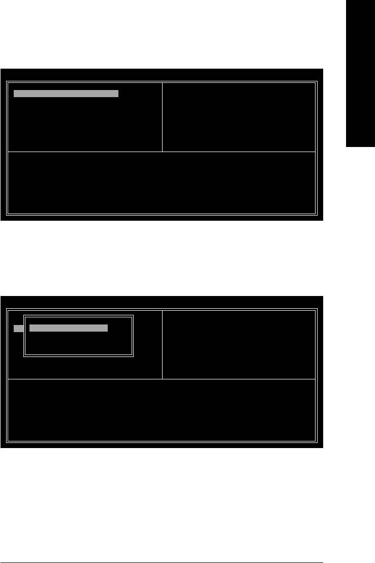
Exploring the Q-Flash
/ Dual BIOS utility screen
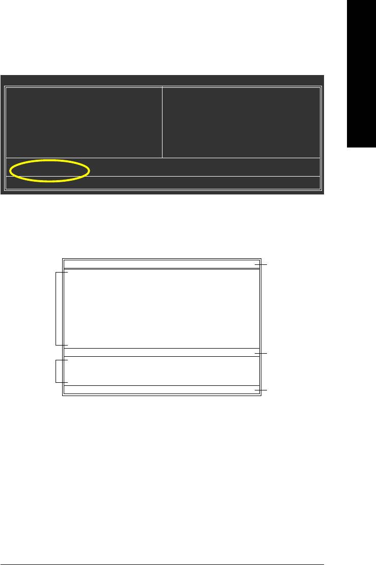
The Q-Flash / Dual BIOS utility screen consists of the following key components.
Dual BIOS Utility
Dual BIOS utility bar
Boot From......................................... Main Bios
Main ROM Type/Size.............................SST 49LF003A 512K
Backup ROM Type/Size.........................SST 49LF003A 512K
Task menu for
Wide Range Protection Disable
Dual BIOS
Boot From Main Bios
Auto Recovery Enable
utility
Halt On Error Disable
Copy Main ROM Data to Backup
Load Default Settings
Save Settings to CMOS
Q-Flash Utility
TM
Q-Flash
utility title
Load Main BIOS from Floppy
Task menu for
bar
Load Backup BIOS from Floppy
TM
Save Main BIOS to Floppy
Q-Flash
utility
Save Backup BIOS to Floppy
Enter : Run :Move ESC:Reset F10:Power Off
Action bar
Task menu for Dual BIOS utility:
Contains the names of eight tasks and two item showing information about the BIOS ROM type. Blocking a
task and pressing Enter key on your keyboard to enable execution of the task.
Task menu for Q-Flash utility:
Contains the names of four tasks. Blocking a task and pressing Enter key on your keyboard to enable execu-
tion of the task.
Action bar:
Contains the names of four actions needed to operate the Q-Flash/Dual BIOS utility. Pressing the buttons
mentioned on your keyboards to perform these actions.
Appendix- 57 -
TM
Using the Q-Flash
utility:
This section tells you how to update BIOS using the Q-Flash utility. As described in the "Before you begin"
section above, you must prepare a floppy disk having the BIOS file for your motherboard and insert it to your
computer. If you have already put the floppy disk into your system and have entered the Q-Flash utility,
English
please follow the steps below to flash BIOS.
Steps:
1. Press arrow buttons on your keyboard to move the light bar to "Load Main BIOS from Floppy" item in
the Q-Flash menu and press Enter button.
Later, you will see a box pop up showing the BIOS files you previously downloaded to the floppy disk.
If you want to save the current BIOS for backup purpose, you can begin Step 1 with "Save Main
BIOS to Floppy" item.
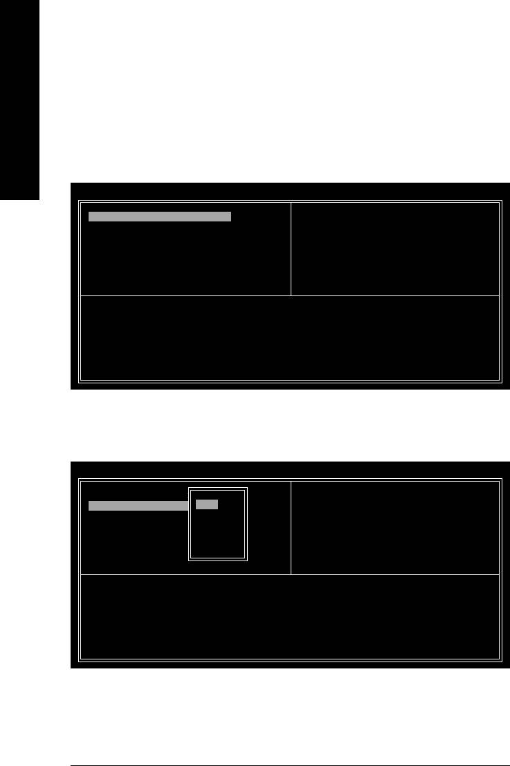
2. Move to the BIOS file you want to flash and press Enter.
In this example, we only download one BIOS file to the floppy disk so only one BIOS file,
8KNXPU.Fba, is listed.
Please confirm again you have the correct BIOS file for your motherboard.
Dual BIOS Utility
Boot From......................................... Main Bios
Main ROM Type/Size.............................SST 49LF003A 512K
Backup ROM Type/Size.........................SST 49LF003A 512K
Wide Range Protection Disable
Boot From Main Bios
1 file(s) found
8KNXPU.Fba 512K
BIOS file in the floppy
Auto Recovery Enable
Halt On Error Disable
disk.
Total size : 1.39M Free size : 911.50K
Copy Main ROM Data to Backup
F5 : Refresh DEL : Delete
Load Default Settings
Save Settings to CMOS
Q-Flash Utility
Load Main BIOS from Floppy
Load Backup BIOS from Floppy
Save Main BIOS to Floppy
Save Backup BIOS to Floppy
Enter : Run :Move ESC:Reset F10:Power Off
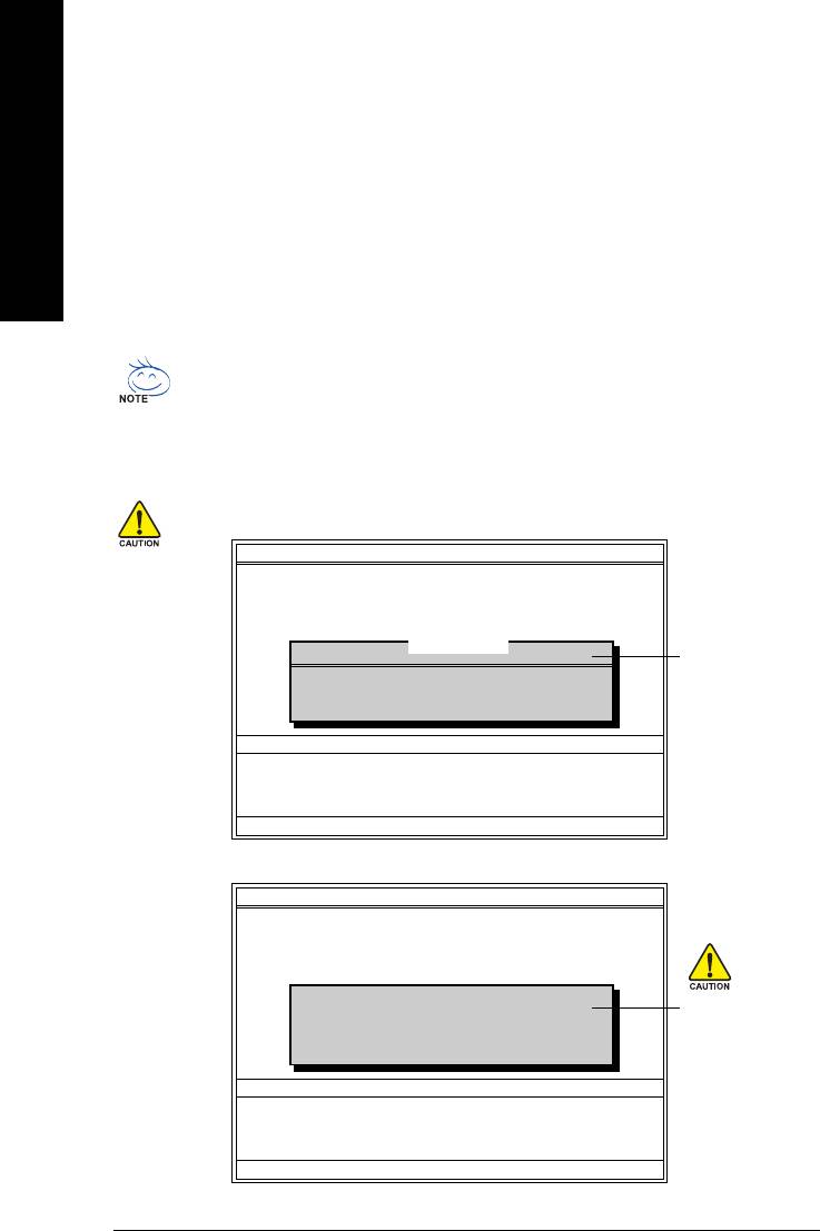
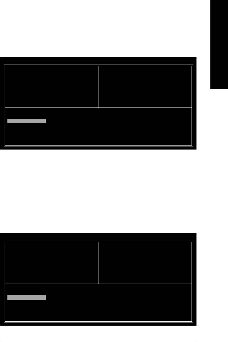
After pressing Enter, you'll then see the progress of reading the BIOS file from the floppy disk.
Dual BIOS Utility
Boot From......................................... Main Bios
Main ROM Type/Size.............................SST 49LF003A 512K
Backup ROM Type/Size.........................SST 49LF003A 512K
Wide Range Protection Disable
Boot From Main Bios
Reading BIOS file from floppy ...
Auto Recovery Enable
Do not turn off power or
>>>>>>>>>>>>>>.....................
Halt On Error Disable
reset your system at this
Copy Main ROM Data to Backup
Don't Turn Off Power or Reset System
Load Default Settings
stage!!
Save Settings to CMOS
Q-Flash Utility
Load Main BIOS from Floppy
Load Backup BIOS from Floppy
Save Main BIOS to Floppy
Save Backup BIOS to Floppy
Enter : Run :Move ESC:Reset F10:Power Off
After BIOS file is read, you'll see a confirmation dialog box asking you "Are you sure to update BIOS?"
GA-8VM800PMD-775 Motherboard - 58 -
3. Press Y button on your keyboard after you are sure to update BIOS.
English
Then it will begin to update BIOS. The progress of updating BIOS will be displayed.
Please do not take out the floppy disk when it begins flashing BIOS.
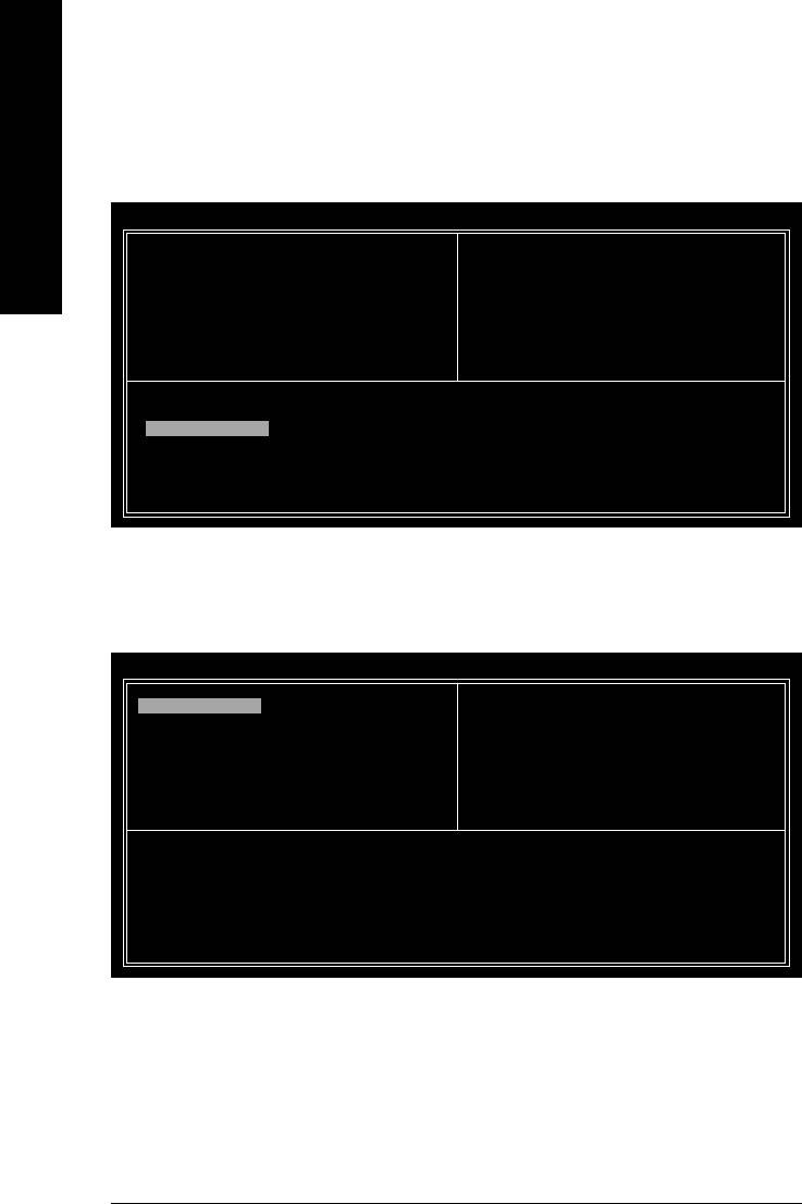
4. Press any keys to return to the Q-Flash menu when the BIOS updating procedure is completed.
Dual BIOS Utility
Boot From......................................... Main Bios
Main ROM Type/Size.............................SST 49LF003A 512K
Backup ROM Type/Size.........................SST 49LF003A 512K
Wide Range Protection Disable
You can repeat Step 1 to
Boot From Main Bios
!! Copy BIOS completed - Pass !!
Auto Recovery Enable
4 to flash the backup
Halt On Error Disable
BIOS, too.
Copy Main ROM Data to Backup
Please press any key to continue
Load Default Settings
Save Settings to CMOS
Q-Flash Utility
Load Main BIOS from Floppy
Load Backup BIOS from Floppy
Save Main BIOS to Floppy
Save Backup BIOS to Floppy
Enter : Run :Move ESC:Reset F10:Power Off
5. Press Esc and then Y button to exit the Q-Flash utility. The computer will restart automatically after
you exit Q-Flash.
Dual BIOS Utility
Boot From......................................... Main Bios
Main ROM Type/Size.............................SST 49LF003A 512K
Backup ROM Type/Size.........................SST 49LF003A 512K
Wide Range Protection Disable
Boot From Main Bios
Auto Recovery Enable
Are you sure to RESET ?
Halt On Error Disable
Copy Main ROM Data to Backup
[Enter] to continure or [Esc] to abort...
Load Default Settings
Save Settings to CMOS
Q-Flash Utility
Load Main BIOS from Floppy
Load Backup BIOS from Floppy
Save Main BIOS to Floppy
Save Backup BIOS to Floppy
Enter : Run :Move ESC:Reset F10:Power Off
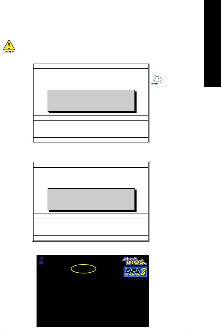
After system reboots, you may find the BIOS version on your boot screen becomes the one you flashed.
Award Modular BIOS v6.00PG, An Energy Star Ally
Copyright (C) 1984-2003, Award Software, Inc.
Intel i875P AGPset BIOS for 8KNXP Ultra Fba
The BIOS file
Check System Health OK , VCore = 1.5250
Main Processor : Intel Pentium(R) 4 1.6GHz (133x12)
becomes Fab after
<CPUID : 0F27 Patch ID : 0027>
Memory Testing : 131072K OK
updating.
Memory Frequency 266 MHz in Single Channel
Primary Master : FUJITSU MPE3170AT ED-03-08
Primary Slave : None
Secondary Master : CREATIVEDVD-RM DVD1242E BC101
Secondary Slave : None
Press DEL to enter SETUP / Dual BIOS / Q-Flash / F9 For
Xpress Recovery
09/23/2003-i875P-6A79BG03C-00
Appendix- 59 -
6. Press Del to enter BIOS menu after system reboots. When you are in BIOS menu, move to
Load Fail-Safe Defaults item and press Enter to load BIOS Fail-Safe Defaults. Normally the system
redetects all devices after BIOS has been upgraded. Therefore, we highly recommend reloading the
BIOS defaults after BIOS has been upgraded.
English
CMOS Setup Utility-Copyright (C) 1984-2004 Award Software
Standard CMOS Features
Select Language
Advanced BIOS Features
Load Fail-Safe Defaults
Integrated Peripherals
Load Optimized Defaults
Power Management Setup
Load Fail-Safe Defaults (Y/N)? Y
Set Supervisor Password
PnP/PCI Configurations
Set User Password
PC Health Status
Save & Exit Setup
MB Intelligent Tweaker(M.I.T.)
Exit Without Saving
ESC: Quit F3: Change Language
F8: Dual BIOS/Q-Flash F10: Save & Exit Setup
Time, Date, Hard Disk Type...
Press Y on your keyboard to load defaults.
7. Select Save & Exit Setup item to save the settings to CMOS and exit the BIOS menu.
System will reboot after you exit the BIOS menu. The procedure is completed.
CMOS Setup Utility-Copyright (C) 1984-2004 Award Software
Standard CMOS Features
Select Language
Advanced BIOS Features
Load Fail-Safe Defaults
Integrated Peripherals
Load Optimized Defaults
Power Management Setup
Save to CMOS and EXIT (Y/N)? Y
Set Supervisor Password
PnP/PCI Configurations
Set User Password
PC Health Status
Save & Exit Setup
MB Intelligent Tweaker(M.I.T.)
Exit Without Saving
ESC: Quit F3: Change Language
F8: Dual BIOS/Q-Flash F10: Save & Exit Setup
Time, Date, Hard Disk Type...
Press Y on your keyboard to save and exit.
Part Two:
TM
Updating BIOS with Q-Flash
Utility on Single-BIOS Motherboards.
TM
This part guides users of single-BIOS motherboards how to update BIOS using the Q-Flash
utility.
CMOS Setup Utility-Copyright (C) 1984-2004 Award Software
Standard CMOS Features
Top Performance
Advanced BIOS Features
Load Fail-Safe Defaults
Integrated Peripherals
Load Optimized Defaults
Power Management Setup
Set Supervisor Password
PnP/PCI Configurations
Set User Password
PC Health Status
Save & Exit Setup
MB Intelligent Tweaker(M.I.T.)
Exit Without Saving
ESC: Quit F3: Change Language
F8: Q-Flash F10: Save & Exit Setup
Time, Date, Hard Disk Type...
GA-8VM800PMD-775 Motherboard - 60 -
TM
Exploring the Q-Flash
utility screen
English
The Q-FlashBIOS utility screen consists of the following key components.
TM
Q-Flash Utility V1.30
Q-Flash
utility bar
Flash Type/Size.................................SST 49LF003A 256K
Keep DMI Data Enable
Task menu for
Update BIOS from Floppy
TM
Q-Flash
utility
Save BIOS to Floppy
Enter : Run :Move ESC:Reset F10:Power Off
Action bar
Task menu for Q-Flash utility:
Contains the names of three tasks. Blocking a task and pressing Enter key on your keyboard to enable
execution of the task.
Action bar:
Contains the names of four actions needed to operate the Q-Flash utility. Pressing the buttons mentioned on
your keyboards to perform these actions.
TM
Using the Q-Flash
utility:
This section tells you how to update BIOS using the Q-Flash utility. As described in the "Before you begin"
section above, you must prepare a floppy disk having the BIOS file for your motherboard and insert it to your
computer. If you have already put the floppy disk into your system and have entered the Q-Flash utility,
please follow the steps below to flash BIOS.
Steps:
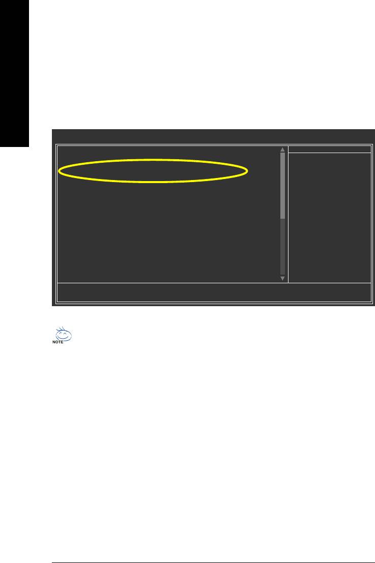
1. Press arrow buttons on your keyboard to move the light bar to "Update BIOS from Floppy" item in the
Q-Flash menu and press Enter button.
Later, you will see a box pop up showing the BIOS files you previously downloaded to the floppy disk.
If you want to save the current BIOS for backup purpose, you can begin Step 1 with "Save BIOS
to Floppy" item.
2. Move to the BIOS file you want to flash and press Enter.
In this example, we only download one BIOS file to the floppy disk so only one BIOS file,
8GE800.F4, is listed.
Please confirm again you have the correct BIOS file for your motherboard.
Q-Flash Utility V1.30
Flash Type/Size.................................SST 49LF003A 256K
1 file(s) found
8GE800.F4 256K
Keep DMI Data Enable
BIOS file in the floppy
Update BIOS from Floppy
Save BIOS to Floppy
disk.
Total size : 1.39M Free size : 1.14M
Enter : Run :Move ESC:Reset F10:Power Off
F5 : Refresh DEL : Delete
Q-Flash Utility V1.30
Flash Type/Size.................................SST 49LF003A 256K
Keep DMI Data Enable
Reading BIOS file from floppy ...
Do not turn off power or
>>>>>>>>>>>>>>.....................
Update BIOS from Floppy
reset your system at
Save BIOS to Floppy
Enter : Run :Move ESC:Reset F10:Power Off
Don't Turn Off Power or Reset System
this stage!!
After BIOS file is read, you'll see a confirmation dialog box asking you "Are you sure to update BIOS?"
Please do not take out the floppy disk when it begins flashing BIOS.
Appendix- 61 -
3. Press Y button on your keyboard after you are sure to update BIOS.
Then it will begin to update BIOS. The progress of updating BIOS will be shown at the same time.
Q-Flash Utility V1.30
Flash Type/Size.................................SST 49LF003A 256K
English
Keep DMI Data Enable
Updating BIOS Now
Do not turn off power or
Update BIOS from Floppy
>>>>>>>>>>>>>>>>>>>.........................
Save BIOS to Floppy
reset your system
Enter : Run :Move ESC:Reset F10:Power Off
Don't Turn Off Power or Reset System
at this stage!!
4. Press any keys to return to the Q-Flash menu when the BIOS updating procedure is completed.
Q-Flash Utility V1.30
Flash Type/Size.................................SST 49LF003A 256K
Keep DMI Data Enable
!! Copy BIOS completed - Pass !!
Update BIOS from Floppy
Save BIOS to Floppy
Please press any key to continue
Enter : Run :Move ESC:Reset F10:Power Off
5. Press Esc and then Y button to exit the Q-Flash utility. The computer will restart automatically after
you exit Q-Flash.
Q-Flash Utility V1.30
Flash Type/Size.................................SST 49LF003A 256K
Keep DMI Data Enable
Are you sure to RESET ?
Update BIOS from Floppy
Save BIOS to Floppy
[Enter] to continure or [Esc] to abort...
Enter : Run :Move ESC:Reset F10:Power Off
After system reboots, you may find the BIOS version on your boot screen becomes the one you flashed.
Award Modular BIOS v6.00PG, An Energy Star Ally
Copyright (C) 1984-2003, Award Software, Inc.
Intel 845GE AGPSet BIOS for 8GE800 F4
The BIOS file
Check System Health OK
Main Processor : Intel Pentium(R) 4 1.7GHz (100x17.0)
becomes F4 after
<CPUID : 0F0A Patch ID : 0009>
Memory Testing : 122880K OK + 8192K Shared Memory
updating
Primary Master : FUJITSU MPE3170AT ED-03-08
Primary Slave : None
Secondary Master : CREATIVEDVD-RM DVD1242E BC101
Secondary Slave : None
Press DEL to enter SETUP / Q-Flash
03/18/2003-I845GE-6A69YG01C-00
6. Press Del to enter BIOS menu after system reboots and "Load BIOS Fail-Safe Defaults". See how
to Load BIOS Fail-Safe Defaults, please kindly refer to Step 6 to 7 in Part One.
Congratulation!! You have updated BIOS successfully!!
GA-8VM800PMD-775 Motherboard - 62 -
TM
English
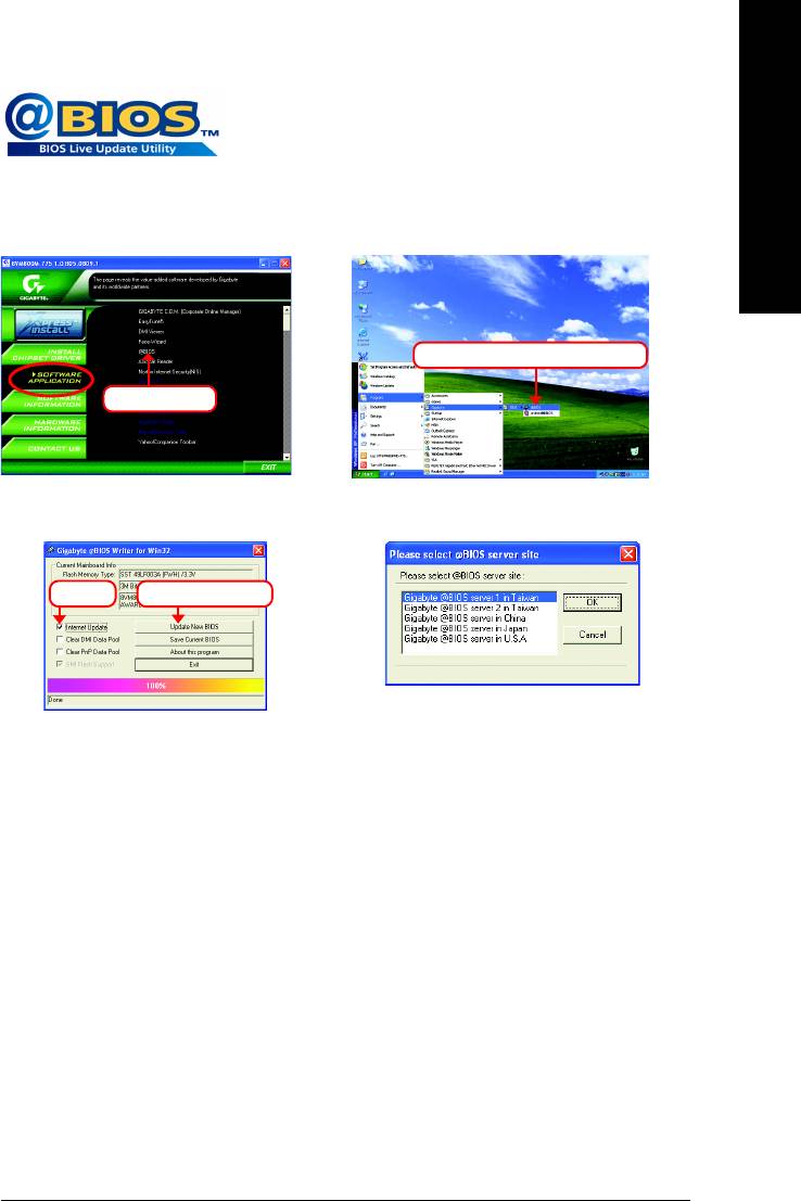
Method 2 : @BIOS
Utility
If you do not have a DOS startup disk, we recommend that you use the
new @BIOS utility. @BIOS allows users to update their BIOS under
Windows. Just select the desired @BIOS server to download the latest
version of BIOS.
Fig 1. Installing the @BIOS utility Fig 2. Installation Complete and Run @BIOS
Click Start/ Programs/ Gigabyte/ BIOS/ @BIOS
Select @BIOS item
Fig 3. The @BIOS Utility Fig 4. Select the desired @BIOS server
Click ""
Click "Update New BIOS"
1. Methods and steps:
I. Update BIOS through Internet
a. Click "Internet Update" icon
b. Click "Update New BIOS" icon
TM
c. Select @BIOS
sever
d. Select the exact model name on your motherboard
e. System will automatically download and update the BIOS.
II. Update BIOS NOT through Internet:
a. Do not click "Internet Update" icon
b. Click "Update New BIOS"
c. Please select "All Files" in dialog box while opening the old file.
d. Please search for BIOS unzip file, downloading from internet or any other methods (such
as: VM800PMD.D1).
e. Complete update process following the instruction.
Appendix- 63 -

III. Save BIOS
In the very beginning, there is "Save Current BIOS" icon shown in dialog box. It means to save the
current BIOS version.
English
IV. Check out supported motherboard and Flash ROM:
In the very beginning, there is "About this program" icon shown in dialog box. It can help you check out
which kind of motherboard and which brand of Flash ROM are supported.
2. Note:
I. In method I, if it shows two or more motherboard's model names to be selected, please make
sure your motherboard's model name again. Selecting wrong model name will cause the
system unbooted.
II. In method II, be sure that motherboard's model name in BIOS unzip file are the same as your
motherboard's. Otherwise, your system won't boot.
TM
III. In method I, if the BIOS file you need cannot be found in @BIOS
server, please go onto
Gigabyte's web site for downloading and updating it according to method II.
IV. Please note that any interruption during updating will cause system unbooted.
V. Do not use @BIOS and C.O.M. (Corporate Online Management) at the same time.
GA-8VM800PMD-775 Motherboard - 64 -

English
4-1-4 Configuring SATA Hard Drive(s)
To configure SATA hard drive(s), follow the steps below:
(1) Install SATA hard drive(s) in your system.
(2) Configure SATA controller mode and boot sequence in BIOS Setup.
(Note)
(3) Configure RAID set in RAID BIOS.
(4) Make a floppy disk containing the SATA controller driver.
(5) Install the SATA controller driver during OS installation.
Before you begin
Please prepare:
(a) Two SATA hard drives (to ensure optimal performance, it is recommended that you use two hard
drives with identical model and capacity). If you do not want to create RAID with the SATA
controller, you may prepare only one hard drive.
(b) An empty formatted floppy disk.
(c) Windows XP/2000 setup disk.
(d) Driver CD for your motherboard.
(1) Install SATA hard drive(s) in your system
Attach one end of the SATA signal cable to the rear of the SATA hard drive and the other end to available
SATA port(s) on the motherboard. (If there are more than one SATA controller on your motherboard, you
may check the name of the SATA connector to identify the SATA controller for the connector. For
example, SATA0_SB/SATA_SB is controlled by the SATA controller on South-Bridge.) Then connect the
power connector from your power supply to the hard drive.
(Note) Skip this step if you do not want to create RAID array on the SATA controller.
Appendix- 65 -
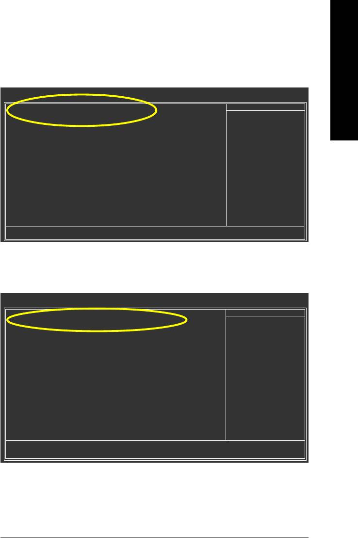
(2) Configuring SATA controller mode and boot sequence in BIOS Setup
You have to make sure whether the SATA controller is configured correctly in system BIOS Setup and
set BIOS boot sequence for the SATA hard drive(s).
Step 1:
English
Turn on your computer and press Del to enter BIOS Setup during POST (Power-On Self Test). If you
want to create RAID, select SATA Mode under the Integrated Peripherals menu (Figure 1) and set
this item to RAID (IDE by default). Set SATA Mode to IDE if you do not want to create RAID.
CMOS Setup Utility-Copyright (C) 1984-2004 Award Software
Integrated Peripherals
OnChip IDE Channel 0 [Enabled]
Item Help
OnChip IDE Channel 1 [Enabled]
Menu Level
OnChip Serial ATA [Enabled]
SATA Mode [IDE]
AC97 Audio [Auto]
USB 1.1 Controller [Enabled]
USB 2.0 Controller [Enabled]
USB Keyboard Support [Disabled]
USB Mouse Support [Disabled]
Onboard H/W LAN [Enabled]
OnBoard LAN Boot ROM [Disabled]
Legacy USB storage detect [Enabled]
Onboard Serial Port 1 [3F8/IRQ4]
Onboard Serial Port 2 [2F8/IRQ3]
Onboard Parallel Port [378/IRQ7]
Parallel Port Mode [SPP]
x EPP Mode Select EPP1.7
: Move Enter: Select +/-/PU/PD: Value F10: Save ESC: Exit F1: General Help
F5: Previous Values F6: Fail-Safe Defaults F7: Optimized Defaults
Figure 1
The BIOS Setup menus described in this section may not show the exact settings for your
motherboard. The actual BIOS Setup menu options you will see shall depend on the motherboard
you have and the BIOS version.
GA-8VM800PMD-775 Motherboard - 66 -
Step 2:
English
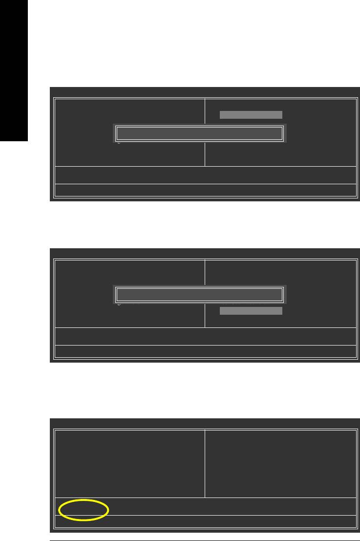
Later, select Hard Disk Boot Priority under the Advanced BIOS Features menu. In the Hard Disk
Boot Priority submenu, select the model of the SATA hard drive onto which you intent to install
Microsoft Windows 2000/XP (Figure 2).
CMOS Setup Utility-Copyright (C) 1984-2004 Award Software
Hard Disk Boot Priority
1. SCSI-0 : ST3120026AS
Item Help
2. SCSI-1 : ST3120026AS
Menu Level
3. Bootable Add-in Cards
Use <> or <> to
select a device, then
press <+> to move it
up, or <-> to move it
down the list. Press
<ESC> to exit this
menu.
: Move PU/PD/+/-: Change Priority F10: Save ESC: Exit
Figure 2
Step 3:
Set First Boot Device under the Advanced BIOS Features menu to CDROM to boot from CD-ROM
after system restarts (Figure 3).
CMOS Setup Utility-Copyright (C) 1984-2004 Award Software
Advanced BIOS Features
Hard Disk Boot Priority [Press Enter]
Item Help
First Boot Device [CDROM]
Menu Level
Second Boot Device [Hard Disk]
Third Boot Device [CDROM]
Password Check [Setup]
# CPU Hyper-Threading [Enabled]
Limit CPUID Max. to 3 [Disabled]
(Note)
No-Execute Memory Protect
[Enabled]
(Note)
CPU Enhanced Halt (C1E)
[Enabled]
(Note)
CPU Thermal Monitor 2(TM2)
[Enabled]
(Note)
CPU EIST Function
[Enabled]
: Move Enter: Select +/-/PU/PD: Value F10: Save ESC: Exit F1: General Help
F5: Previous Values F6: Fail-Safe Defaults F7: Optimized Defaults
Figure 3
Step 4:
Save and exit BIOS Setup.
Appendix- 67 -

(3) Configuring RAID set in RAID BIOS
Enter the RAID BIOS setup utility to configure a RAID array. Skip this step and proceed to Section 4 if
you do not want to create RAID.
English
Step 1:
After the POST memory test begins and before the operating system boot begins, the following
information will appear on screen (Figure 4). Press the TAB key to enter the VT8237 Serial ATA RAID
BIOS configuration utility.
VIA Technologies, Inc. VIA VT8237 Serial ATA RAID BIOS Setting Utility V2.31
Copyright (C) VIA Technologies, Inc. All Right reserved.
Scan Devices, Please wait...
Press <Tab> key into User Window!
Serial_Ch0 Master : ST3120026AS
Serial_Ch1 Master : ST3120026AS
Figure 4
Step 2:
In the VT8237 SATA RAID BIOS utility screen (Figure 5), you can use the UP or DOWN ARROW key
to highlight through choices. Highlight an item that you want to execute and press ENTER.
VIA Tech. VT8237 SATA RAID BIOS Ver 2.31
Create Array
Create a RAID array with
Delete Array
the hard disks attached to
Create/Delete Spare
VIA RAID controller
Select Boot Array
Serial Number View
F1 : View Array/disk Status
,
: Move to next item
Enter : Confirm the selection
ESC : Exit
Channel Drive Name Array Name Mode Size(GB) Status
Serial_Ch0 Master ST3120026AS SATA 111.79 Hdd
Serial_Ch1 Master ST3120026AS SATA 111.79 Hdd
Figure 5
GA-8VM800PMD-775 Motherboard - 68 -
A. Create Array:
English
In Main Menu, select Create Array and press ENTER, a screen similar to Figure 6 below will appear.
VIA Tech. VT8237 SATA RAID BIOS Ver 2.31
Auto Setup For Performance
Create a RAID array with
Array Mode RAID 0 (Striping)
the hard disks attached to
Select Disk Drives
VIA RAID controller
Block Size 64K
Start Create Process
F1 : View Array/disk Status
,
: Move to next item
Enter : Confirm the selection
ESC : Exit
Channel Drive Name Array Name Mode Size(GB) Status
Serial_Ch0 Master ST3120026AS SATA 111.79 Hdd
Serial_Ch1 Master ST3120026AS SATA 111.79 Hdd
Figure 6
The first step to create a RAID array is to set the RAID mode. Select Array Mode and press ENTER.
And the RAID mode selection menu will appear (Figure 7). The supported RAID modes include RAID
0 for performance, RAID 1 for data protection, and RAID SPAN for capacity. Use the UP or
DOWN ARROW key to select a RAID mode.
VIA Tech. VT8237 SATA RAID BIOS Ver 2.31
Auto Setup For Data Security
Create a RAID array with
Array Mode RAID 0 (Striping)
RAID 0 for performance
the hard disks attached to
Select Disk Drives
RAID 1 for data protection
VIA RAID controller
Block Size 64K
RAID SPAN for capacity
Start Create Process
F1 : View Array/disk Status
,
: Move to next item
Enter : Confirm the selection
ESC : Exit
Channel Drive Name Array Name Mode Size(GB) Status
Serial_Ch0 Master ST3120026AS SATA 111.79 Hdd
Serial_Ch1 Master ST3120026AS SATA 111.79 Hdd
Figure 7
Appendix- 69 -
After selecting a RAID mode, you must decide whether you want the RAID array to be configured
automatically or manually.
Auto Setup allows BIOS to assign the hard drives and create arrays automatically, but it does not
duplicate the mirroring drives even if user selects Create and duplicate for RAID 1. It is recom-
English
mended all hard drives are new ones when you want to create an array.
Select Disk Drives lets users select the array drives by their requirements. Select the Select Disk
Drives item and press ENTER, use the ARROW keys to select the target hard drive(s). The selected
hard drives will be marked with an asterisk (Figure 8).
VIA Tech. VT8237 SATA RAID BIOS Ver 2.31
Auto Setup For Performance
Create a RAID array with
Array Mode RAID 0 (Striping)
the hard disks attached to
Select Disk Drives
VIA RAID controller
Block Size 64K
Start Create Process
F1 : View Array/disk Status
,
: Move to next item
Enter : Confirm the selection
ESC : Exit
Channel Drive Name Array Name Mode Size(GB) Status
[*]Serial_Ch0 Master ST3120026AS SATA 111.79 Stripe0
[*]Serial_Ch1 Master ST3120026AS SATA 111.79 Stripe1
Figure 8
If you select to create RAID 0 array manually, you can specify the block size. Use the UP or DOWN
ARROW keys to select Block Size and press ENTER. Select the block size from the popup menu. The
block size can be set between 4KB to 64KB (Figure 9).
VIA Tech. VT8237 SATA RAID BIOS Ver 2.31
Auto Setup For Performance
Create a RAID array with
Array Mode RAID 0 (Striping)
4K
the hard disks attached to
Select Disk Drives
8K
VIA RAID controller
Block Size 64K
16K
Start Create Process
32K
F1 : View Array/disk Status
64K
,
: Move to next item
Enter : Confirm the selection
ESC : Exit
Channel Drive Name Array Name Mode Size(GB) Status
[*]Serial_Ch0 Master ST3120026AS SATA 111.79 Stripe0
[*]Serial_Ch1 Master ST3120026AS SATA 111.79 Stripe1
Figure 9
Next, use the ARROW keys to select Start Create Process and press ENTER. The prompt "The data
on the selected disks will be destroied. Continue? (Y/N)" will appear. Press Y to confirm or N to
abort.
Important All existing contents in the hard drive will be destroyed after the array creation.
GA-8VM800PMD-775 Motherboard - 70 -
B. Delete Array:
English
If you want to delete an existing array, select Delete Array in Main Menu and press ENTER. The
channel column will be activated. Select the member of an array that is to be deleted and press ENTER.
A warning message will show up, press Y to confirm or press N to cancel (Figure 10).
VIA Tech. VT8237 SATA RAID BIOS Ver 2.31
Create Array
Delete a RAID array contain
Delete Array
the hard disks attached to
Create/Delete Spare
VIA RAID controller
Select Boot Array
Serial Number View
F1 : View Array/disk Status
,
: Move to next item
The selected array will be destoried.
Enter : Confirm the selection
Are you sure? Continue? Press Y/N
ESC : Exit
Channel Drive Name Array Name Mode Size(GB) Status
[*]Serial_Ch0 Master ST3120026AS ARRAY 0 SATA 111.79 Stripe0
[*]Serial_Ch1 Master ST3120026AS ARRAY 0 SATA 111.79 Stripe1
Figure 10
Deleting a disk array will destroy all the data on the disk array except for RAID 1 array(s). When a RAID
1 array is deleted, the data on the two hard drives will be reserved and the two hard drives will become
two normal drives.
C. Select Boot Array:
You can select a disk array as boot device if you want to boot operating system from an array. Boot
disk array cannot be selected if the operating system does not boot from the disk array. Highlight the
Select Boot Array item in Main Menu; press ENTER and the channel column will be activated. Then
highlight the target disk array and press ENTER. Press ESC to go back to Main Menu. If you want to
cancel the boot array setting, select the disk array that has an asterisk and press ENTER, its boot
setting will be canceled (Figure 11).
VIA Tech. VT8237 SATA RAID BIOS Ver 2.31
Create Array
Set/Clear bootable array
Delete Array
Create/Delete Spare
Select Boot Array
Serial Number View
F1 : View Array/disk Status
,
: Move to next item
Enter : Confirm the selection
ESC : Exit
Channel Drive Name Array Name Mode Size(GB) Status
[*]Serial_Ch0 Master ST3120026AS ARRAY 0 SATA 111.79 Boot
[*]Serial_Ch1 Master ST3120026AS ARRAY 0 SATA 111.79 Boot
Figure 11
Appendix- 71 -
D. Serial Number View:
Highlight Serial Number View and press ENTER. Use the ARROW keys to select a drive, and the
selected drive's serial number can be viewed in the last line. The serial number is assigned by the disk
drive manufacturer (Figure 12).
English
VIA Tech. VT8237 SATA RAID BIOS Ver 2.31
Create Array
View the serial number of
Delete Array
hard disk, it is useful for
Create/Delete Spare
identify same model disks
Select Boot Array
Serial Number View
F1 : View Array/disk Status
,
: Move to next item
Enter : Confirm the selection
ESC : Exit
Channel Drive Name Array Name Mode Size(GB) Status
Serial_Ch0 Master ST3120026AS ARRAY 0 SATA 111.79 Stripe0
Serial_Ch1 Master ST3120026AS ARRAY 0 SATA 111.79 Stripe1
Serial Number: 3JT354CP
Figure 12
E. View Array Status:
Press F1 to show the array status on the lower screen. If there are no disk arrays then nothing will be
displayed on the screen (Figure 13).
VIA Tech. VT8237 SATA RAID BIOS Ver 2.31
Create Array
Create a RAID array with
Delete Array
the hard disks attached to
Create/Delete Spare
VIA RAID controller
Select Boot Array
Serial Number View
F1 : View Array/disk Status
,
: Move to next item
Enter : Confirm the selection
ESC : Exit
Array Name Array Mode Block Size(GB) Size(GB)
ARRAY 0 Stripe 64K 223.58
Figure 13
GA-8VM800PMD-775 Motherboard - 72 -
(4) Making a SATA Driver Disk
English
To install operating system onto a serial ATA hard disk on the VT8237 controllers successfully, you
need to install the SATA controller driver during OS installation. Without the driver, the hard disk may not
be recognized during the Windows setup process. First of all, copy the driver for the SATA controller
from the motherboard driver CD-ROM to a floppy disk. See the instructions below about how to copy
(Note 1)
the driver in MS-DOS mode
. Prepare a startup disk that has CD-ROM support and a blank
formatted floppy disk.
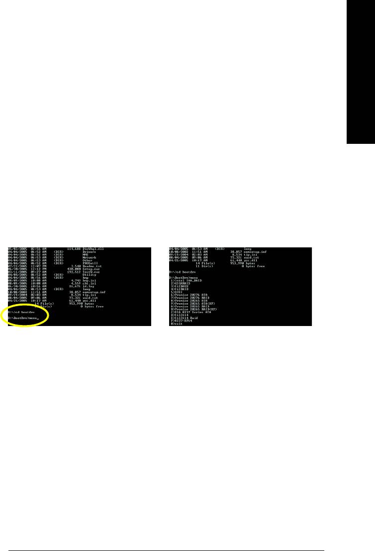
Step 1: Insert the prepared startup disk and motherboard driver CD-ROM in your system. Boot from the
startup disk. Once at the A:\> prompt, change to the CD-ROM drive (example: D:\>). At the D:\> prompt, type
the following two commands. Press ENTER after each command (Figure14):
cd bootdrv
menu
Step 2: When the controller menu (Figure 15) appears, remove the startup disk and insert the blank
formatted disk. Press C to select the C) VIA 8237 Series ATA item. Then it will take about one minute
to copy the SATA driver from the motherboard driver CD to the floppy disk.
(Note 2)
Figure 14 Figure 15
Step 3:
Press 0 to exit when the procedure is complete. You have copied the SATA driver successfully.
(Note 1) For users without a startup disk.
Use an alternative system and insert the GIGABYTE motherboard drive CD-ROM. From the
CD-ROM drive (example: D:\) double click the MENU.exe file in the BootDrv folder. A
command prompt window will open similar to that in Figure 15.
(Note 2) If you wish to install 64-bit Windows Operating System, select F) 8237-XP64.
Appendix- 73 -

(5) Installing SATA controller driver during OS installation
Now that you have prepared the SATA driver disk and configured BIOS settings, you are ready to install
Windows 2000/XP onto your SATA hard drive with the SATA driver. The following is an example of
Windows XP installation.
English
Step 1: Restart your system to boot from the Windows 2000/XP Setup disk and press F6 as soon as
you see the "Press F6 if you need to install a 3rd party SCSI or RAID driver" message (Figure 16). After
pressing F6, there will be a few moments of some files being loaded before you see the next screen.
Windows Setup
Press F6 if you need to install a 3rd party SCSI or RAID driver.
Figure 16
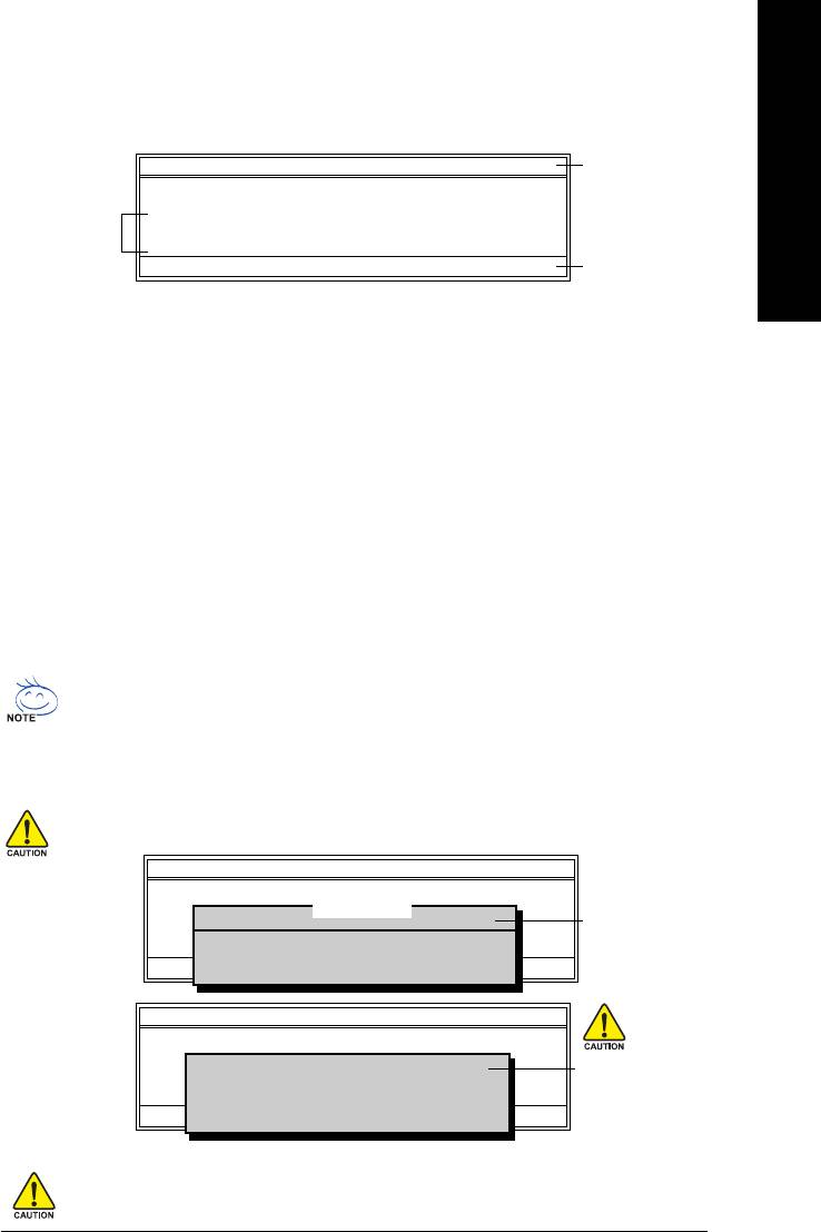
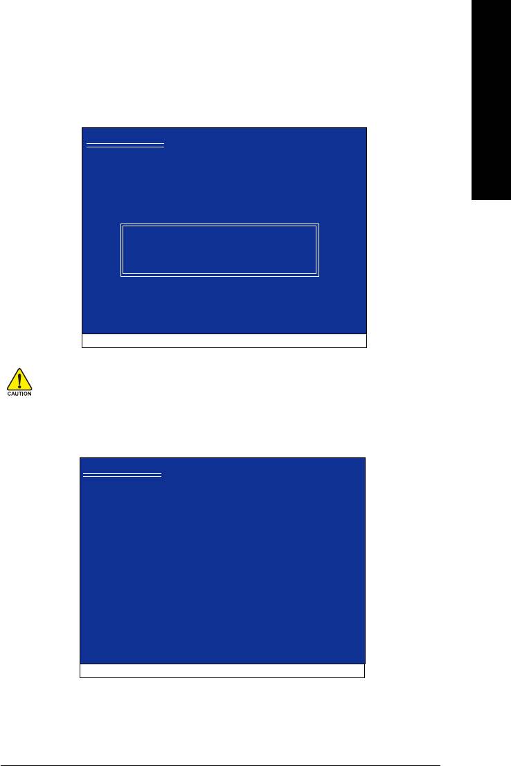
Step 2:
When a screen similar to that below appears, insert the floppy disk containing the SATA driver and press
S (Figure 17).
Windows Setup
Setup could not determine the type of one or more mass storage devices
installed in your system, or you have chosen to manually specify an adapter.
Currently, Setup will load support for the following mass storage devices(s)
<none>
* To specify additional SCSI adapters, CD-ROM drives, or special
disk controllers for use with Windows, including those for
which you have a device support disk from a mass storage device
manufacturer, press S.
* If you do not have any device support disks from a mass storage
device manufacturer, or do not want to specify additional
mass storage devices for use with Windows, press ENTER.
S=Specify Additional Device ENTER=Continue F3=Exit
Figure 17
GA-8VM800PMD-775 Motherboard - 74 -
Step 3:
English
If Setup correctly recognizes the driver in the floppy disk, a controller menu similar to Figure 18 below
will appear. If you want to install Windows XP, use the ARROW keys to select VIA Serial ATA RAID
(Note)
Controller(Windows XP)
and press ENTER. Then it will begin to load the SATA driver from the
floppy disk.
Windows Setup
You have chosen to configure a SCSI Adapter for use with Windows,
using a device support disk provided by an adapter manufacturer.
Select the SCSI Adapter you want from the following list, or press ESC
to return to the previous screen.
VIA Serial ATA RAID Controller(Windows XP)
VIA Serial ATA RAID Controller(Windows 2000)
VIA Serial ATA RAID Controller(Windows NT4)
VIA ATA/ATAPI Host Controller(Windows XP)
ENTER=Select F3=Exit
Figure 18
If a message appears saying one or some file(s) cannot be found, please check the floppy
disk or copy the correct SATA driver again from the motherboard driver CD.
Step 4:
When the screen as shown below appears, press ENTER to continue the SATA driver installation from
the floppy disk. The driver installation will be finished in about one minute.
Windows Setup
Setup will load support for the following mass storage device(s):
VIA Serial ATA RAID Controller(Windows XP)
* To specify additional SCSI adapters, CD-ROM drives, or special
disk controllers for use with Windows, including those for
which you have a device support disk from a mass storage device
manufacturer, press S.
* If you do not have any device support disks from a mass storage
device manufacturer, or do not want to specify additional
mass storage devices for use with Windows, press ENTER.
S=Specify Additional Device Enter=Continue F3=Exit
Figure 19
(Note) If you want to create a RAID array, select the item depending on the operating system that you
want to install. (Windows XP, Windows 2000 or Windows NT4). If you do not want create a
RAID array, select VIA ATA/ATAPI Host Controller(Windows XP).
Appendix- 75 -

After the SATA controller driver installation is completed, you should see a screen as below. It indicates
that you have installed the SATA controller driver successfully. You can proceed with the Windows
2000/XP installation.
English
WindowsXP Professional Setup
Welcome to Setup.
This port of the Setup program prepares Microsoft(R)
Windows (R) XP to run on your computer.
To set up Windows XP now, press ENTER.
To repair a Windows XP installation using
Recovery Console, press R.
To quit Setup without installing Windows XP, press F3.
Enter= Continue R=Repair F3=Exit
Figure 20
(Note: Each time you add a new hard drive to a RAID array, the RAID driver will have to be installed
under Windows once for that hard drive. After that, the driver will not have to be installed.)
GA-8VM800PMD-775 Motherboard - 76 -
English
4-1-5 2 / 4 / 6 Channel Audio Function Introduction
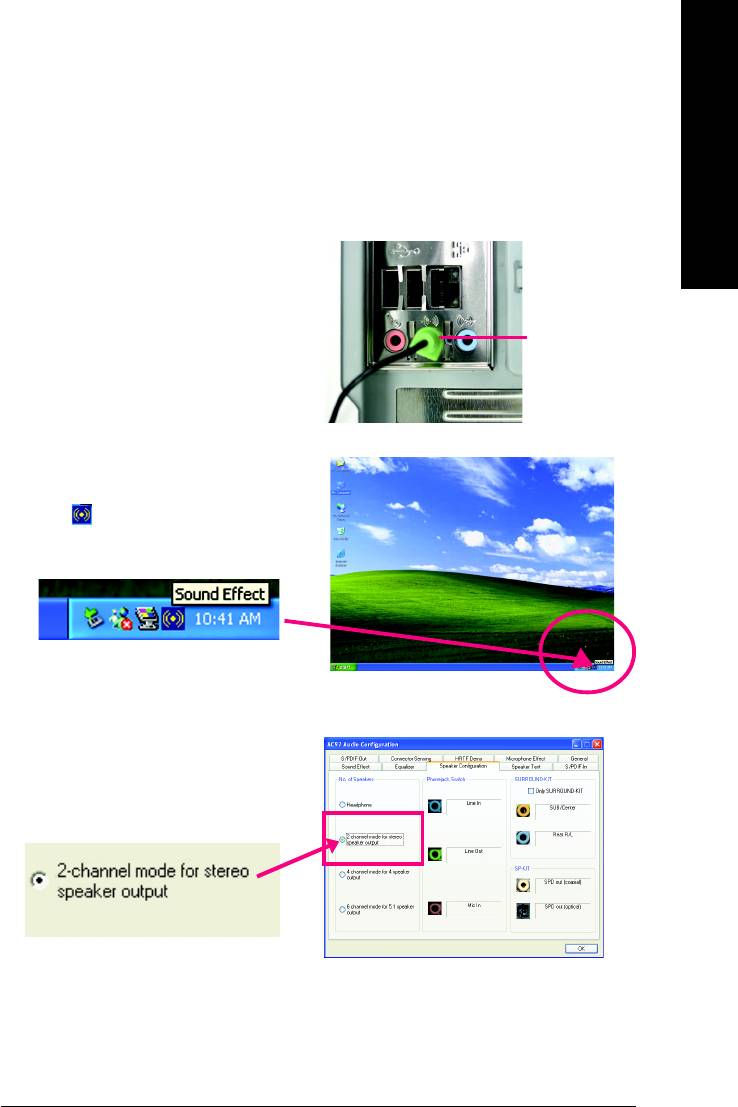
2 Channel Audio Setup
We recommend that you use speakers with amplifier to get the best sound effect if the stereo output is
applied.
STEP 1:
Connect the stereo speakers or earphone to
"Line Out."
Line Out
STEP 2:
After installing the audio driver, you'll find a Sound
Effect icon on the lower right hand taskbar. Click
the icon to select the function.
STEP 3:
On the AC97 Audio Configuration menu, click the
Speaker Configuration tab and select the
2-channel mode for stereo speaker output check
box.
Appendix- 77 -
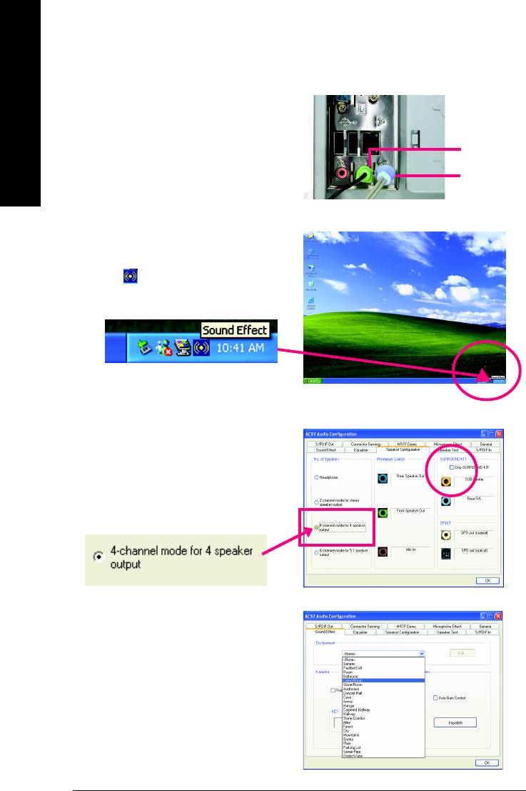
4 Channel Analog Audio Output Mode
STEP 1:
Connect the front channels to "Line Out,"
English
the rear channels to "Line In."
Line Out
Line In
STEP 2:
After installing the audio driver, you'll find a Sound
Effect icon on the lower right hand taskbar. Click
the icon to select the function.
STEP 3:
On the AC97 Audio Configuration menu, click the
Speaker Configuration tab and select the
4-channel mode for 4 speaker output check
box.
Clear the Only SURROUND-KIT check box and press
OK.
When the Environment setting is None, the sound
would be performed as stereo mode (2-channel
output). Please select other settings (ex: Living
Room) for 4-channel output.
GA-8VM800PMD-775 Motherboard - 78 -
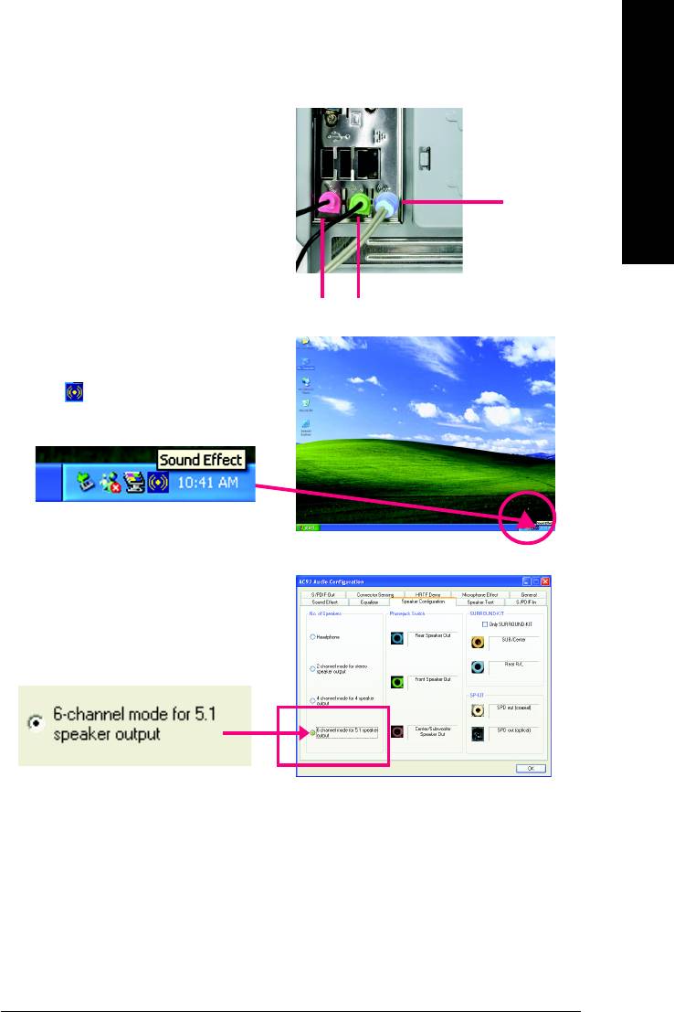
Basic 6 Channel Analog Audio Output Mode
English
Use the back audio panel to connect the audio output
without any additional module.
STEP 1:
Connect the front channels to "Line Out",the rear
channels to "Line In", and the Center/Subwoofer chan-
Line In
nels to "MIC In".
MIC In
Line Out
STEP 2:
After installing the audio driver, you'll find a Sound
Effect icon on the lower right hand taskbar. Click
the icon to select the function.
STEP 3:
On the AC97 Audio Configuration menu, click the
Speaker Configuration tab and select the 6-chan-
nel mode for 5.1 speaker output check box.
Clear the Only SURROUND-KIT check box and press
OK.
Appendix- 79 -
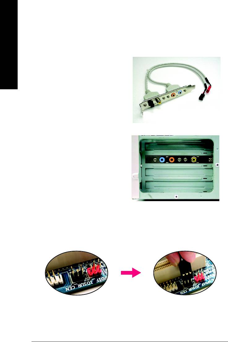
Advanced 6 Channel Analog Audio Output Mode (using Audio Combo Kit,Optional Device):
(Audio Combo Kit provides SPDIF output port : optical & coaxis and SURROUND-KIT : Rear R/L & CEN /
Subwoofer)
English
SURROUND-KIT access analog output to rear
channels and Center/Subwoofer channels. It is the
best solution if you need 6 channel output, Line In
and MIC at the same time. "SURROUND-KIT" is in-
cluded in the GIGABYTE unique "Audio Combo Kit"
as picture.
STEP 1:
Secure the metal bracket of the"Surround Kit" to the
chassis back panel with a screw.
STEP 2:
Connect the "SURROUND-KIT" cable to the SUR_CEN connector on the M/B.
GA-8VM800PMD-775 Motherboard - 80 -
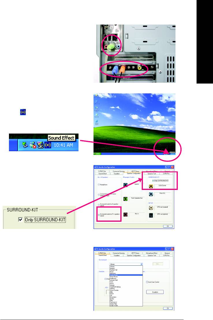
STEP 3:
English
Connect the front channels to back audio panel's
"Line Out", the rear channels to SURROUND-KIT's
REAR R/L, and the Center/Subwoofer channels to
SURROUND-KIT's SUB CENTER.
STEP 4:
After installing the audio driver, you'll find a Sound
Effect icon on the lower right hand taskbar. Click
the icon to select the function.
STEP 5:
On the AC97 Audio Configuration menu, click the
Speaker Configuration tab and select the 6-chan-
nel mode for 5.1 speaker output check box.
Select the Only SURROUND-KIT check box and
press OK.
Basic & Advanced 6 Channel Analog Audio Output Mode Notes:
When the Environment setting is None, the sound
would be performed as stereo mode (2-channel
output). Please select the other settings for 6
channels output.
Appendix- 81 -
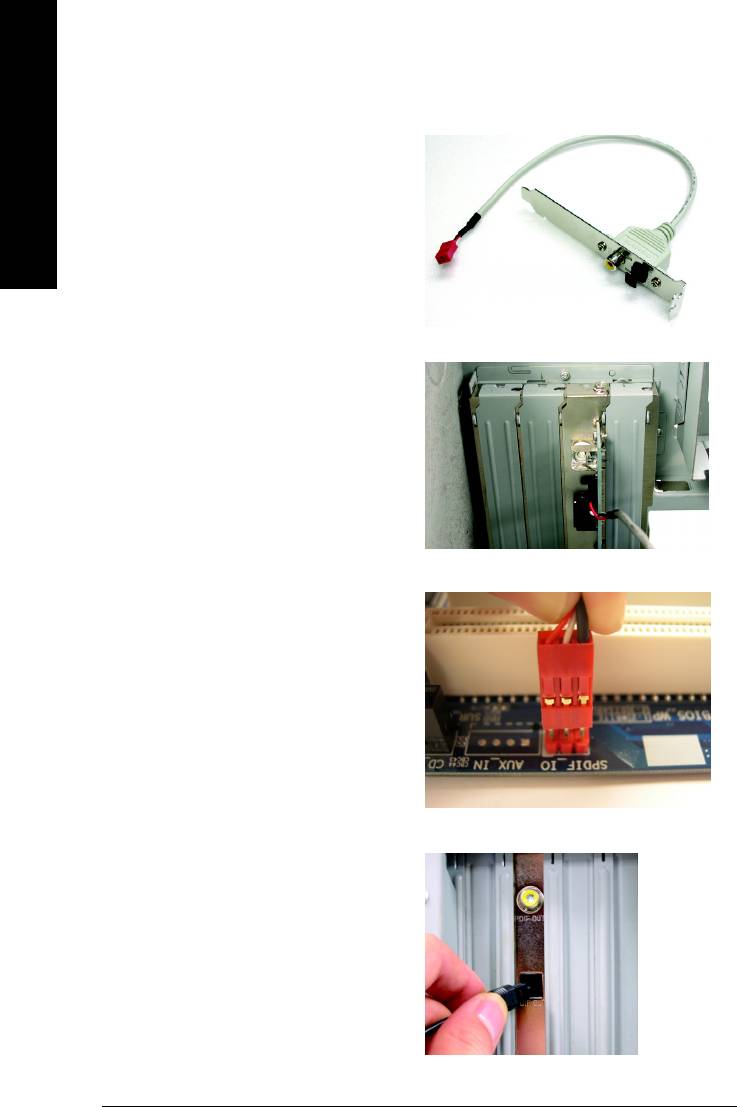
SPDIF Output Device (Optional Device)
A "SPDIF output" connector is available on the
motherboard. Cable with rear bracket could link to
English
the "SPDIF output" connector (As picture.) For the
further linkage to decoder, rear bracket provides
coaxial cable and Fiber connecting port.
STEP 1:
Secure the metal bracket of the SPDIF Output
device to the chassis back panel with a screw.
STEP 2:
Connect the SPDIF device cable to the SPDIF_IO
connector on the motherboard.
STEP 3:
Connect SPDIF to the SPDIF decoder.
GA-8VM800PMD-775 Motherboard - 82 -

English
4-2 Troubleshooting
Below is a collection of general asked questions. To check general asked questions based on a specific
motherboard model, please log on to http://www.gigabyte.com.tw
Question 1: I cannot see some options that were included in previous BIOS after updating BIOS. Why?
Answer: Some advanced options are hidden in new BIOS version. Please press Ctrl and F1 keys after
entering BIOS menu and you will be able to see these options.
Questions 2: Why is the light of my keyboard/optical mouse still on after computer shuts down?
Answer: In some boards, a small amount of electricity is kept on standby after computer shuts down and
that's why the light is still on.
Question 3: How do I clear CMOS?
Answer: If your board has a Clear CMOS jumper, please refer to the Clear CMOS steps in the manual. If your
board doesn't have such jumper, you can take off the on-board battery to leak voltage to clear CMOS.
Please refer to the steps below:
Steps:
1. Turn off power.
2. Disconnect the power cord from MB.
3. Take out the battery gently and put it aside for about 10 minutes (Or you can use a metal object to
connect the positive and negative pins in the battery holder to makethem short for one minute).
4. Re-insert the battery to the battery holder.
5. Connect power cord to MB again and turn on power.
6. Press Del to enter BIOS and load Fail-Safe Defaults(or load Optimized Defaults).
7. Save changes and reboot the system.
Question 4: Why do I still get a weak sound after turning up the speaker to the maximum volume?
Answer: Please make sure the speaker you are using is equipped with an internal amplifier. If not, please
change another speaker with power/amplifier and try again later.
Question 5: Sometimes I hear different continuous beeps from computer after system boots up. What do
these beeps usually stand for?
Answer: The beep codes below may help you identify the possible computer problems. However, they are
only for reference purposes. The situations might differ from case to case.
AMI BIOS Beep Codes
AWARD BIOS Beep Codes
*
Computer gives 1 short beep when system boots successfully.
1 short: System boots successfully
*Except for beep code 8, these codes are always fatal.
2 short: CMOS setting error
1 beep Refresh failure
1 long 1 short: DRAM or M/B error
2 beeps Parity error
1 long 2 short: Monitor or display card error
3 beeps Base 64K memory failure
1 long 3 short: Keyboard error
4 beeps Timer not operational
1 long 9 short: BIOS ROM error
5 beeps Processor error
Continuous long beeps: DRAM error
6 beeps 8042 - gate A20 failure
Continuous short beeps: Power error
7 beeps Processor exception interrupt error
8 beeps Display memory read/write failure
9 beeps ROM checksum error
10 beeps CMOS shutdown register read/write error
11 beeps Cache memory bad
Appendix- 83 -

English
GA-8VM800PMD-775 Motherboard - 84 -

English
Appendix- 85 -

English
GA-8VM800PMD-775 Motherboard - 86 -

English
Contact Us
Taiwan (Headquarters)
Japan
GIGA-BYTE TECHNOLOGY CO., LTD.
NIPPON GIGA-BYTE CORPORATION
Address: No.6, Bau Chiang Road, Hsin-Tien, Taipei 231,
WEB address : http://www.gigabyte.co.jp
Taiwan
Singapore
TEL: +886-2-8912-4888
GIGA-BYTE SINGAPORE PTE. LTD.
FAX: +886-2-8912-4003
Tech. Support :
Tech. Support :
http://tw.giga-byte.com/TechSupport/ServiceCenter.htm
http://tw.giga-byte.com/TechSupport/ServiceCenter.htm
Non-Tech. Support(Sales/Marketing) :
Non-Tech. Support(Sales/Marketing) :
http://ggts.gigabyte.com.tw/nontech.asp
http://ggts.gigabyte.com.tw/nontech.asp
WEB address: http://www.gigabyte.com.sg
WEB address (English): http://www.gigabyte.com.tw
U.K.
WEB address (Chinese): http://chinese.giga-byte.com
G.B.T. TECH. CO., LTD.
U.S.A.
Tech. Support :
G.B.T. INC.
http://tw.giga-byte.com/TechSupport/ServiceCenter.htm
TEL: +1-626-854-9338
Non-Tech. Support(Sales/Marketing) :
FAX: +1-626-854-9339
http://ggts.gigabyte.com.tw/nontech.asp
Tech. Support :
WEB address : http://uk.giga-byte.com
http://tw.giga-byte.com/TechSupport/ServiceCenter.htm
The Netherlands
Non-Tech. Support(Sales/Marketing) :
GIGA-BYTE TECHNOLOGY B.V.
http://ggts.gigabyte.com.tw/nontech.asp
Tech. Support :
WEB address : http://www.giga-byte.com
http://tw.giga-byte.com/TechSupport/ServiceCenter.htm
Germany
Non-Tech. Support(Sales/Marketing) :
G.B.T. TECHNOLOGY TRADING GMBH
http://ggts.gigabyte.com.tw/nontech.asp
Tech. Support :
WEB address : http://www.giga-byte.nl
http://tw.giga-byte.com/TechSupport/ServiceCenter.htm
Non-Tech. Support(Sales/Marketing) :
http://ggts.gigabyte.com.tw/nontech.asp
WEB address : http://www.gigabyte.de
Appendix- 87 -

China
Russia
NINGBO G.B.T. TECH. TRADING CO., LTD.
Moscow Representative Office Of GIGA-BYTE Technology
Tech. Support :
Co., Ltd.
http://tw.giga-byte.com/TechSupport/ServiceCenter.htm
Tech. Support :
English
Non-Tech. Support(Sales/Marketing) :
http://tw.giga-byte.com/TechSupport/ServiceCenter.htm
http://ggts.gigabyte.com.tw/nontech.asp
Non-Tech. Support(Sales/Marketing) :
WEB address : http://www.gigabyte.com.cn
http://ggts.gigabyte.com.tw/nontech.asp
Shanghai
WEB address : http://www.gigabyte.ru
TEL: +86-021-63410999
Poland
FAX: +86-021-63410100
Office of GIGA-BYTE TECHNOLOGY Co., Ltd. in POLAND
Beijing
Tech. Support :
TEL: +86-10-62102838
http://tw.giga-byte.com/TechSupport/ServiceCenter.htm
FAX: +86-10-62102848
Non-Tech. Support(Sales/Marketing) :
Wuhan
http://ggts.gigabyte.com.tw/nontech.asp
TEL: +86-27-87851061
WEB address : http://www.gigabyte.pl
FAX: +86-27-87851330
Serbia & Montenegro
GuangZhou
Representative Office Of GIGA-BYTE Technology Co., Ltd. in
TEL: +86-20-87586074
SERBIA & MONTENEGRO
FAX: +86-20-85517843
Tech. Support :
Chengdu
http://tw.giga-byte.com/TechSupport/ServiceCenter.htm
TEL: +86-28-85236930
Non-Tech. Support(Sales/Marketing) :
FAX: +86-28-85256822
http://ggts.gigabyte.com.tw/nontech.asp
Xian
WEB address: http://www.gigabyte.co.yu
TEL: +86-29-85531943
Czech Republic
FAX: +86-29-85539821
Representative Office Of GIGA-BYTE Technology Co., Ltd. in
Shenyang
CZECH REPUBLIC
TEL: +86-24-23960918
Tech. Support :
FAX: +86-24-23960918-809
http://tw.giga-byte.com/TechSupport/ServiceCenter.htm
Australia
Non-Tech. Support(Sales/Marketing) :
GIGABYTE TECHNOLOGY PTY. LTD.
http://ggts.gigabyte.com.tw/nontech.asp
Tech. Support :
WEB address: http://www.gigabyte.cz
http://tw.giga-byte.com/TechSupport/ServiceCenter.htm
Romania
Non-Tech. Support(Sales/Marketing) :
Representative Office Of GIGA-BYTE Technology Co., Ltd. in
http://ggts.gigabyte.com.tw/nontech.asp
Romania
WEB address : http://www.giga-byte.com.au
Tech. Support :
France
http://tw.giga-byte.com/TechSupport/ServiceCenter.htm
GIGABYTE TECHNOLOGY FRANCE S.A.R.L.
Non-Tech. Support(Sales/Marketing) :
Tech. Support :
http://ggts.gigabyte.com.tw/nontech.asp
http://tw.giga-byte.com/TechSupport/ServiceCenter.htm
WEB address: http://www.gigabyte.com.ro
Non-Tech. Support(Sales/Marketing) :
http://ggts.gigabyte.com.tw/nontech.asp
WEB address : http://www.gigabyte.fr
GA-8VM800PMD-775 Motherboard - 88 -


