Gigabyte GA-8I845GV: Chapter 2 Hardware Installation Process
Chapter 2 Hardware Installation Process: Gigabyte GA-8I845GV
English
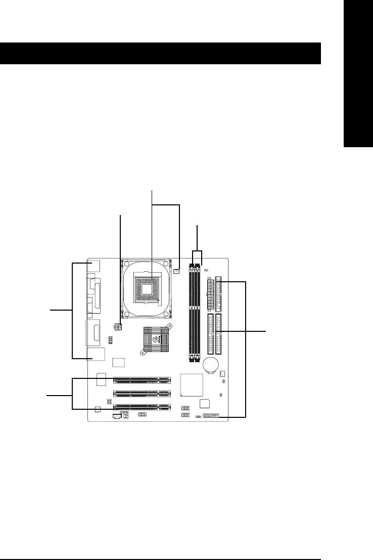
Chapter 2 Hardware Installation Process
To set up your computer, you must complete the following steps:
Step 1- Install the Central Processing Unit (CPU)
Step 2- Install memory modules
Step 3- Install expansion cards
Step 4- Connect ribbon cables, cabinet wires, and power supply
Step 1
Step 4
Step 2
Step 4
Step 4
Step 3
Congratulations! You have accomplished the hardware installation!
Turn on the power supply or connect the power cable to the power outlet. Continue with the
BIOS/software installation.
- 9 - Hardware Installation Process
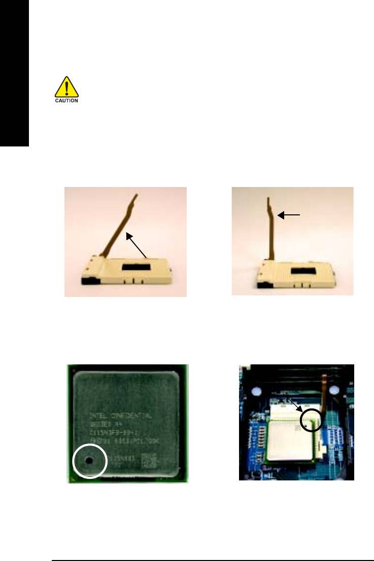
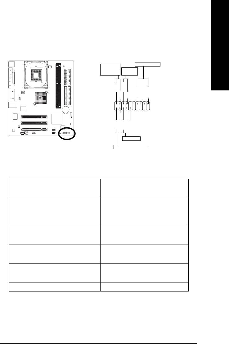
Step 1: Install the Central Processing Unit (CPU)
Before installing the processor, adhere to the following warning:
English
1.Please make sure the CPU type is supported by the motherboard.
2.If you do not match the CPU socket Pin 1 and CPU cut edge well, it will
cause improper installation. Please change the insert orientation.
Step 1-1: CPU Installation
Socket
Angling the
Actuation
0
rod to 65
Lever
1. Angling the rod to 65-degree maybe
2. Pull the rod to the 90-degree directly.
feel a kind of tight , and then continue
pull the rod to 90-degree when a noise
"cough" made.
Pin1 indicator
Pin1 indicator
3. CPU Top View
4. Locate Pin 1 in the socket and
look for a (golden) cut edge on the
CPU upper corner. Then insert
the CPU into the socket.
- 10 -GA-8I845GV Series Motherboard
English
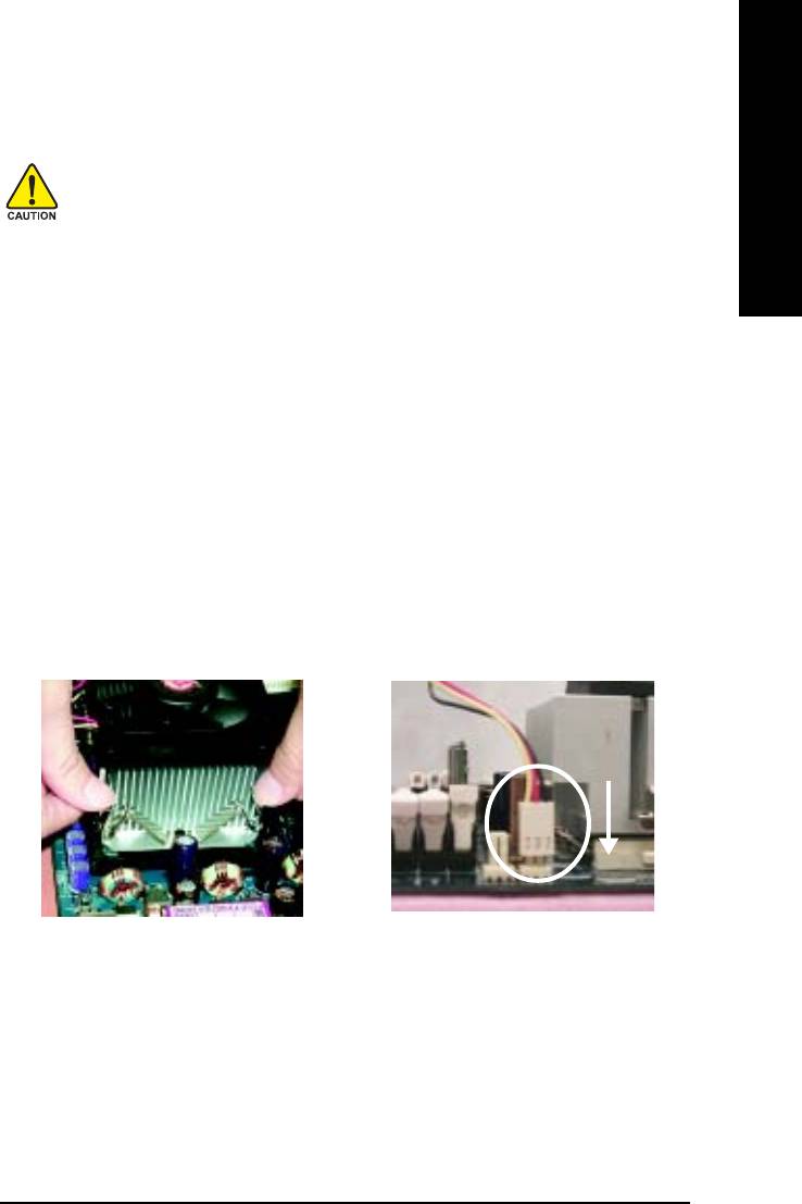
Step 1-2: CPU Cooling Fan Installation
Before installing the CPU cooling fan, adhere to the following warning:
1.Please use Intel approved cooling fan.
2.We recommend you to apply the thermal tape to provide better heat
conduction between your CPU and cooling fan.
(The CPU cooling fan might stick to the CPU due to the hardening of
the thermal paste. During this condition if you try to remove the cool-
ing fan, you might pull the processor out of the CPU socket alone with
the cooling fan, and might damage the processor. To avoid this from
happening, we suggest you to either use thermal tape instead of
thermal paste, or remove the cooling fan with extreme caution.)
3.Make sure the CPU fan power cable is plugged in to the CPU fan
connector, this completes the installation.
Please refer to CPU cooling fan user's manual for more detail
installation procedure.
1. Fasten the cooling fan supporting-
2. Make sure the CPU fan is plugged
base onto the CPU socket on the
to the CPU fan connector, than
motherboard.
install complete.
- 11 - Hardware Installation Process
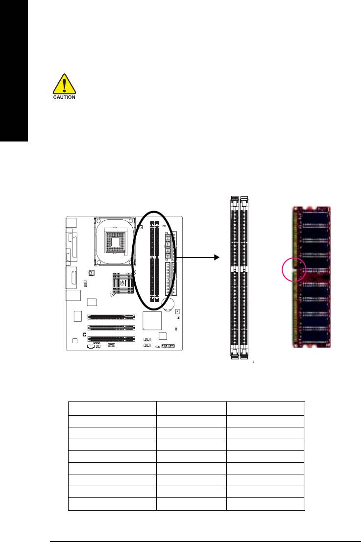
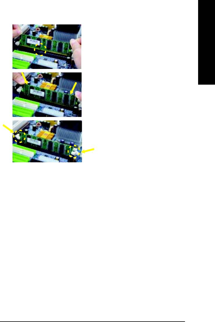
Step 2: Install Memory Modules
Before installing the memory modules, adhere to the following warning:
1.When DIMM LED is ON, do not install / remove DIMM from socket.
English
2.Please note that the DIMM module can only fit in one direction due to
the one notch. Wrong orientation will cause improper installation.
Please change the insert orientation.
The motherboard has 2 dual inline memory module (DIMM) sockets. The BIOS will automatically
detects memory type and size. To install the memory module, just push it vertically into the DIMM
socket. The DIMM module can only fit in one direction due to the notch. Memory size can vary
between sockets.
Notch
DDR
Total Memory Sizes With Unbuffered DDR DIMM
Devices used on DIMM 1 DIMM x 64 2 DIMMs x 64
64 Mbit (2Mx8x4 banks) 128 MBytes 256 MBytes
64 Mbit (1Mx16x4 banks) 32 MBytes 64 MBytes
128 Mbit(4Mx8x4 banks) 256 MBytes 512 MBytes
128 Mbit(2Mx16x4 banks) 64 MBytes 128 MBytes
256 Mbit(8Mx8x4 banks) 512 MBytes 1 GBytes
256 Mbit(4Mx16x4 banks) 128 MBytes 256 MBytes
512 Mbit(16Mx8x4 banks) 1 GBytes 2 GBytes
512 Mbit(8Mx16x4 banks) 256 MBytes 512 MBytes
- 12 -GA-8I845GV Series Motherboard
English
1. The DIMM socket has a notch, so the DIMM
memory module can only fit in one direction.
2. Insert the DIMM memory module vertically into
the DIMM socket. Then push it down.
3. Close the plastic clip at both edges of the DIMM
sockets to lock the DIMM module.
Reverse the installation steps when you wish to
remove the DIMM module.
DDR Introduction
Established on the existing SDRAM infrastructure, DDR (Double Data Rate) memory is a high
performance and cost-effective solution that allows easy adoption for memory vendors, OEMs, and
system integrators.
DDR memory is a great evolutionary solution for the PC industry that builds on the existing
SDRAM architecture, yet make the awesome advances in solving the system performance bottleneck
by doubling the memory bandwidth. Nowadays, with the highest bandwidth of 3.2GB/s of DDR400
memory and complete line of DDR400/333/266/200 memory solutions, DDR memory is the best
choice for building high performance and low latency DRAM subsystem that are suitable for servers,
workstations, and full range of desktop PCs.
- 13 - Hardware Installation Process
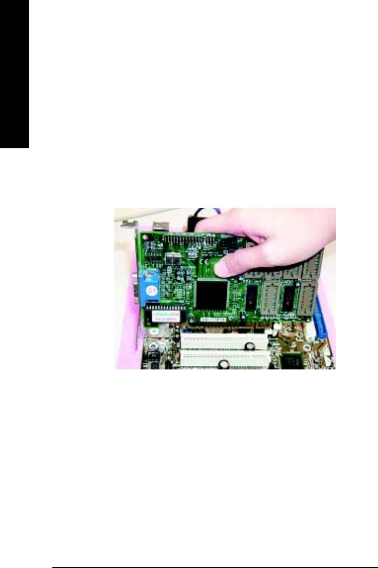
Step 3: Install expansion cards
1. Read the related expansion card's instruction document before install the expansion card into the
computer.
English
2. Remove your computer's chassis cover, screws and slot bracket from the computer.
3. Press the expansion card firmly into expansion slot in motherboard.
4. Be sure the metal contacts on the card are indeed seated in the slot.
5. Replace the screw to secure the slot bracket of the expansion card.
6. Replace your computer's chassis cover.
7. Power on the computer, if necessary, setup BIOS utility of expansion card from BIOS.
8. Install related driver from the operating system.
- 14 -GA-8I845GV Series Motherboard
English
Step 4: Connect ribbon cables, cabinet wires and
power supply
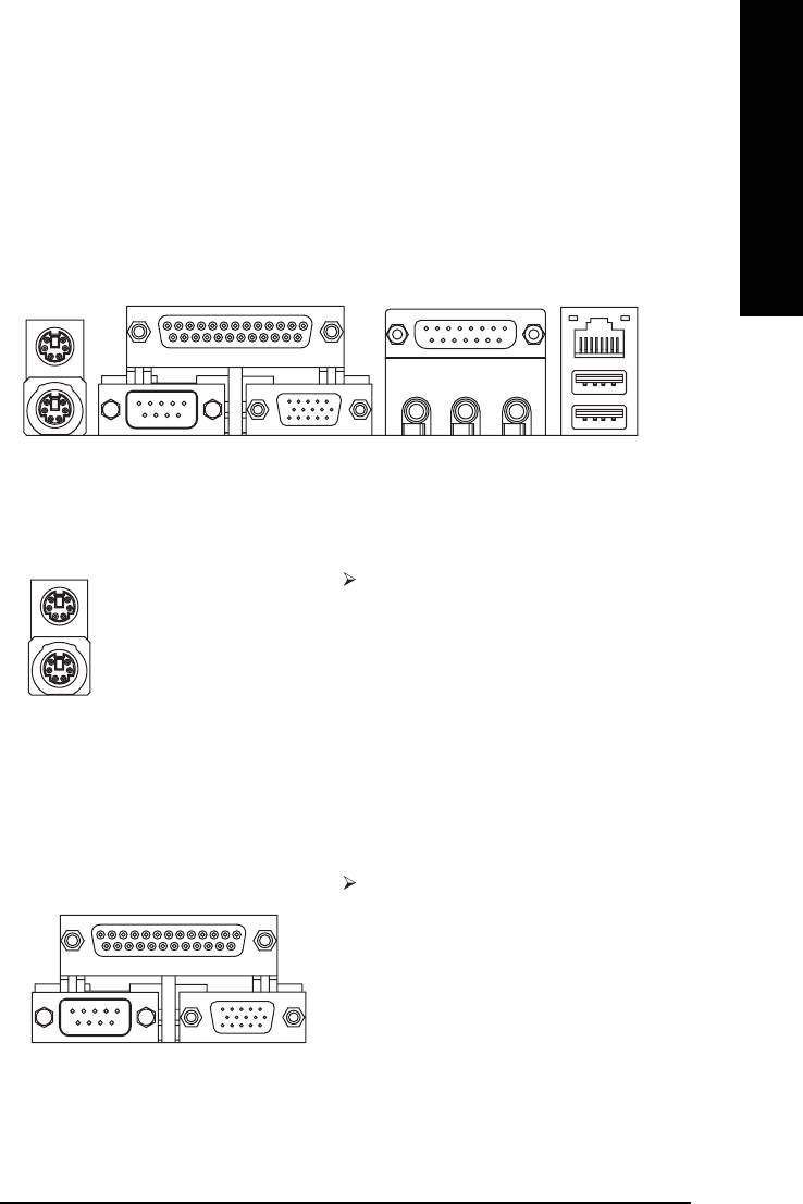
Step 4-1: I/O Back Panel Introduction
Y
Z
\
X
[
XX
XX
X PS/2 Keyboard and PS/2 Mouse Connector
This connector supports standard PS/2
PS/2 Mouse Connector
keyboard and PS/2 mouse.
(6 pin Female)
PS/2 Keyboard Connector
(6 pin Female)
Y Parallel Port, Serial Port and VGA port (LPT / COMA / VGA)
Parallel Port
This connector supports 1 standard COM port,
(25 pin Female)
1 Parallel port and 1 VGA port. Device like printer
can be connected to Parallel port; mouse and
modem etc. can be connected to Serial port.
COMA VGA
Serial Port
VGA Port
(9 pin Male)
(15 pin Female)
- 15 - Hardware Installation Process
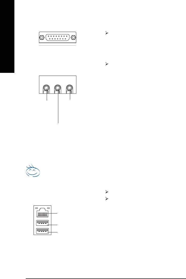
Z Game / MIDI Ports
This connector supports joystick, MIDI keyboard
and other relate audio devices.
English
Joystick / MIDI (15 pin Female)
[ Audio Connectors
After install onboard audio driver, you may
connect speaker to Line Out jack, microphone to
MIC In jack. Device like CD-ROM,walkman etc.
can be connected to Line-In jack.
Please note:
You are able to use 2-/4-/6-channel audio feature
by S/W selection.
Line Out
MIC In
If you want to enable 6-channel function, you
(Front Speaker)
(Center and Subwoofer)
have 2 choose for hardware connection.
Method1:
Connect "Front Speaker" to "Line Out"
Line In
(Rear Speaker)
Connect "Rear Speaker" to "Line In"
Connect "Center and Subwoofer" to "MIC Out ".
Method2:
You can refer to page 24, and contact your
nearest dealer for optional SUR_CEN cable.
If you want the detail information for 2-/4-/6-channel audio setup
installation, please refer to page 72.
\ USB / LAN* Connector
LAN is fast Ethernet with 10/100Mbps speed.*
Before you connect your device(s) into USB
connector(s), please make sure your device(s)
such as USB keyboard,mouse, scanner, zip,
LAN*
speaker...etc. Have a standard USB interface.
USB 0
Also make sure your OS supports USB controller.
USB 1
If your OS does not support USB controller, please
contact OS vendor for possible patch or driver
upgrade. For more information please contact your
OS or device(s) vendors.
* For GA-8I845GV only.
- 16 -GA-8I845GV Series Motherboard
English
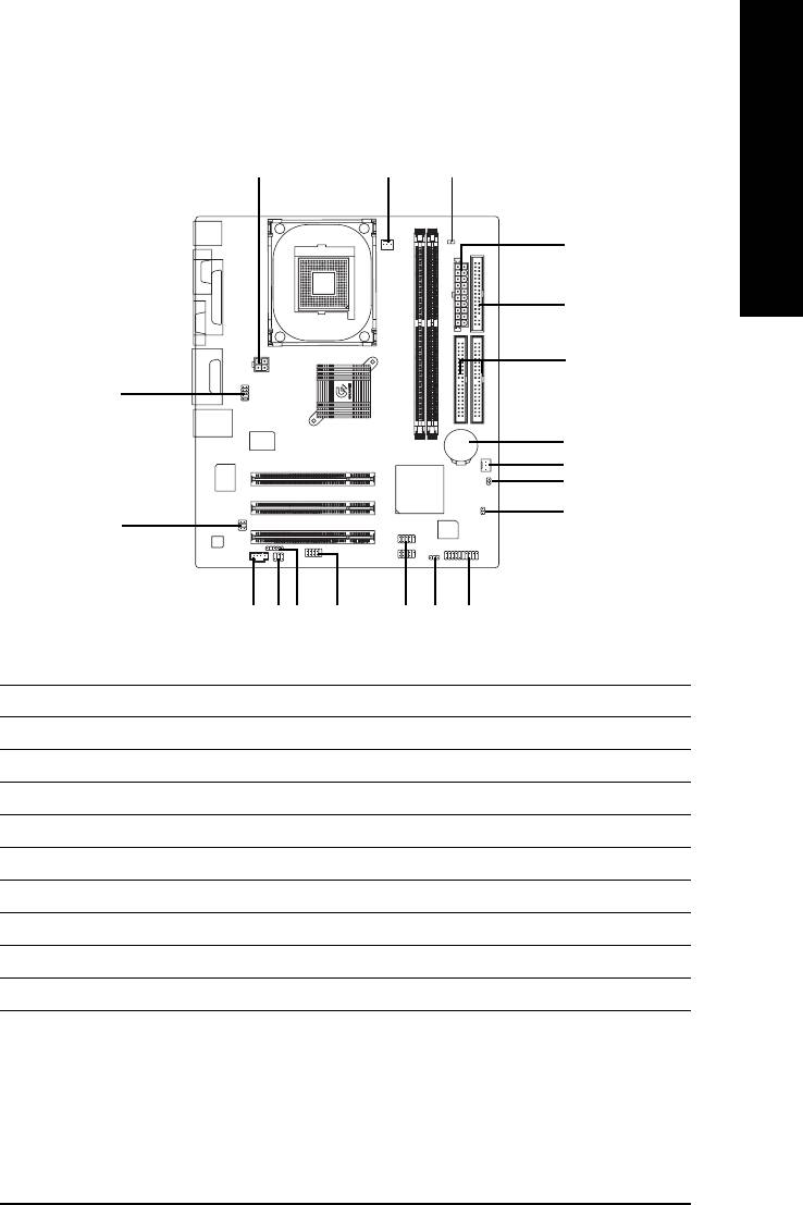
Step 4-2: Connectors Introduction
13
9
2
5
6
10
19
4
18
17
12
11
13
16
15 14
8
7
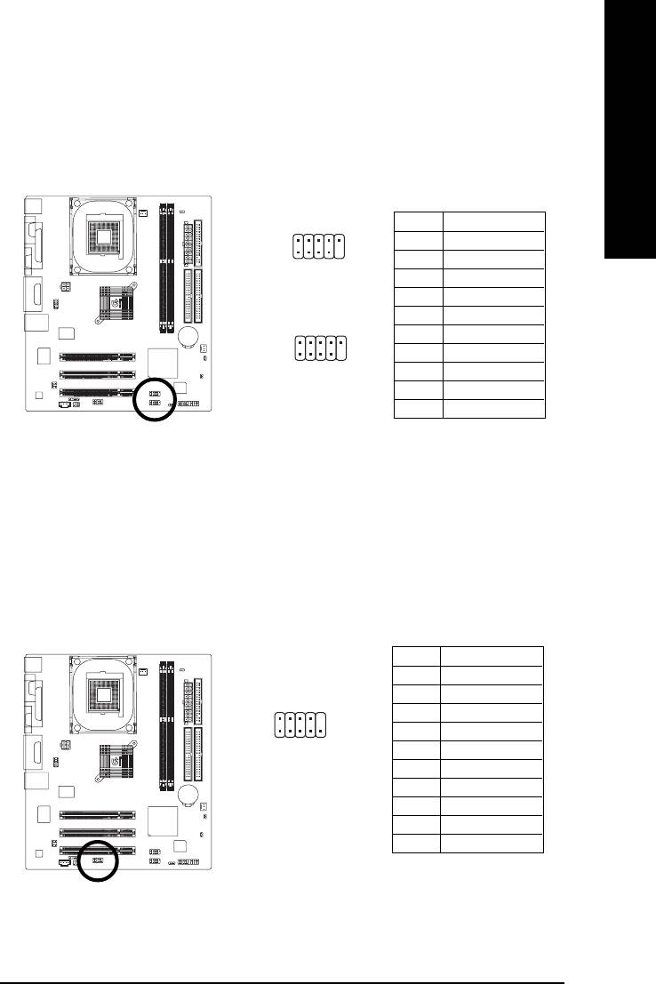
1) ATX_12V
11) CD_IN
2) ATX
12) SUR_CEN
3) CPU_FAN
13) SPDIF_IO
4) SYS_FAN
14) F_USB1 / F_USB2
5) FDD
15) COMB
6) IDE1 / IDE2
16) IR
7) F_PANEL
17) CI
8) PWR_LED
18) CLR_CMOS
9) DIMM_LED
19) BAT
10) F_AUDIO
- 17 - Hardware Installation Process
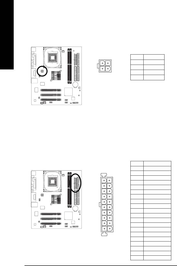
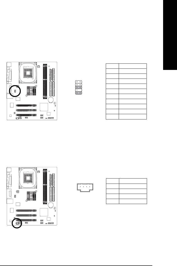
1) ATX_12V (+12V Power Connector)
This connector (ATX_12V) supplies the CPU operation voltage (Vcore).
If this "ATX_12V connector" is not connected, system cannot boot.
English
4
2
Pin No. Definition
1 GND
2 GND
3 +12V
3
1
4 +12V
2) ATX (ATX Power)
AC power cord should only be connected to your power supply unit after ATX power cable and
other related devices are firmly connected to the mainboard.
Pin No. Definition
1 3.3V
2 3.3V
3 GND
11
1
4 VCC
5 GND
6 VCC
7 GND
8 Power Good
9 5V SB (stand by +5V)
10 +12V
11 3.3V
12 -12V
13 GND
20
10
14 PS_ON(soft on/off)
15 GND
16 GND
17 GND
18 -5V
19 VCC
20 VCC
- 18 -GA-8I845GV Series Motherboard
English
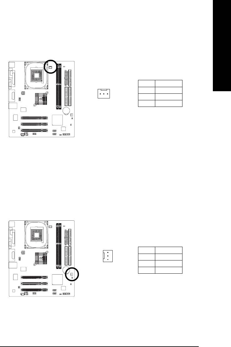
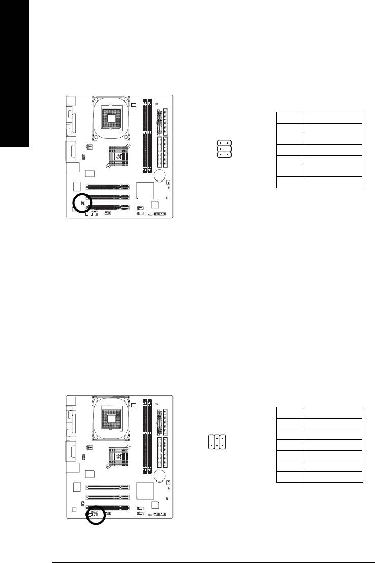
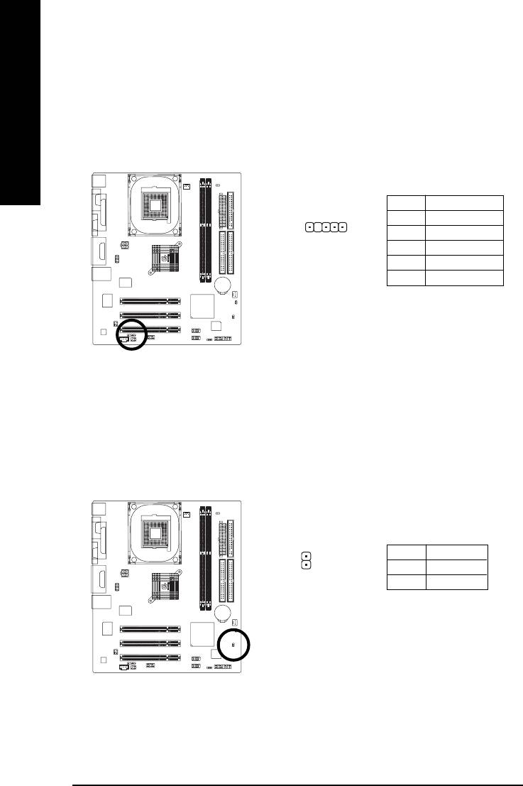
3) CPU_FAN (CPU Fan Connector)
Please note, a proper installation of the CPU cooler is essential to prevent the CPU from running
under abnormal condition or damaged by overheating. The CPU fan connector supports Max.
current up to 600 mA.
Pin No. Definition
1 GND
1
2 +12V
3 Sense
4) SYS_FAN (System Fan Connector)
This connector allows you to link with the cooling fan on the system case to lower the system
temperature.
1
Pin No. Definition
1 GND
2 +12V
3 Sense
- 19 - Hardware Installation Process
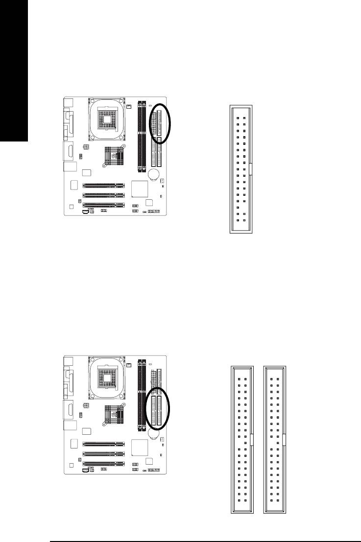
5) FDD (Floppy Connector)
Please connect the floppy drive ribbon cables to FDD. It supports 360K, 1.2M, 720K, 1.44M and
2.88M bytes floppy disk types.
The red stripe of the ribbon cable must be the same side with the Pin1.
English
34
33
2
1
6) IDE1 / IDE2 (IDE1 / IDE2 Connector)
Important Notice:
Please connect first hard disk to IDE1 and connect CD-ROM to IDE2.
The red stripe of the ribbon cable must be the same side with the Pin1.
3940
12
IDE2
IDE1
- 20 -GA-8I845GV Series Motherboard
English
7) F_PANEL (2 x 10 pins Connector)
Please connect the power LED, PC speaker, reset switch and power switch etc of your chassisfront
panel to the F_PANEL connector according to the pin assignment above.
Speaker Connector
Message LED/
Power/
Soft Power
Sleep LED
Connector
PW+
MSG+
MSG-
PW-
SPEAK+
SPEAK-
1
1
1
2
20
1
1
1
19
HD-
RES+
NC
HD+
RES-
Reset Switch
IDE Hard Disk Active LED
HD (IDE Hard Disk Active LED) Pin 1: LED anode(+)
Pin 2: LED cathode(-)
SPK (Speaker Connector) Pin 1: VCC(+)
Pin 2- Pin 3: NC
Pin 4: Data(-)
RES (Reset Switch) Open: Normal Operation
Close: Reset Hardware System
PW (Soft Power Connector) Open: Normal Operation
Close: Power On/Off
MSG (Message LED/ Power/ Sleep LED) Pin 1: LED anode(+)
Pin 2: LED cathode(-)
NC NC
- 21 - Hardware Installation Process
8) PWR_LED
PWR_LED is connect with the system power indicator to indicate whether the system is on/off.
It will blink when the system enters suspend mode. If you use dual color LED, power LED will turn
to another color.
English
Pin No. Definition
1 MPD+
1
2 MPD-
3 MPD-
9) DIMM_LED
Do not remove memory modules while DIMM_LED is on. It might cause short or other unexpected
damages due to the stand by voltage. Remove memory modules only when AC power cord is
disconnected.
_
+
- 22 -GA-8I845GV Series Motherboard
English
10) F_AUDIO (Front Audio Connector)
If you want to use Front Audio connector, you must remove 5-6, 9-10 Jumper.
In order to utilize the front audio header, your chassis must have front audio connector. Also please
make sure the pin assigment on the cable is the same as the pin assigment on the MB header. To
find out if the chassis you are buying support front audio connector, please contact your dealer.
Please note, you can have the alternative of using front audio connector or of using rear audio
connector to play sound.
Pin No. Definition
1 MIC
2 GND
1
2
3 REF
4 Power
5 Front Audio (R)
6 Rear Audio (R)
109
7 Reserved
8 No Pin
9 Front Audio (L)
10 Rear Audio (L)
11) CD_IN (CD In Connector)
Connect CD-ROM or DVD-ROM audio out to the connector.
Pin No. Definition
1 CD-L
1
2 GND
3 GND
4 CD-R
- 23 - Hardware Installation Process
12)SUR_CEN (Surround Center Connector)
Please contact your nearest dealer for optional SUR_CEN cable.
English
Pin No. Definition
1 SUR OUTL
1
2
2 SUR OUTR
3 GND
4 No Pin
65
5 CENTER_OUT
6 BASS_OUT
13)SPDIF_IO (SPDIF In/Out Connector)
The SPDIF output is capable of providing digital audio to external speakers or compressed AC3
data to an external Dolby Digital Decoder. Use this feature only when your stereo system has
digital input function. Be careful with the polarity of the SPDIF_IO connector. Check the pin
assignment carefully while you connect the SPDIF_IO cable, incorrect connection between the
cable and connector will make the device unable to work or even damage it. For optional
SPDIF_IO cable, please contact your local dealer.
Pin No. Definition
1 VCC
2
6
2 No Pin
3 SPDIF
1
4 SPDIFI
5
5 GND
6 GND
- 24 -GA-8I845GV Series Motherboard
English
14)F_USB1 / F_USB2 (Front USB Connector, Yellow)
Be careful with the polarity of the front USB connector. Check the pin assignment carefully while
you connect the front USB cable, incorrect connection between the cable and connector will make
the device unable to work or even damage it. For optional front USB cable, please contact your
local dealer.
2
10
Pin No. Definition
1 Power
F_USB2
2 Power
1
9
3 USB Dx-
4 USB Dy-
5 USB Dx+
2
10
6 USB Dy+
F_USB1
7 GND
1
9
8 GND
9 No Pin
10 NC
15) COMB (COM B Connector)
Be careful with the polarity of the COMB connector. Check the pin assignment carefully while you
connect the COMB cable, incorrect connection between the cable and connector will make the
device unable to work or even damage it. For optional COMB cable, please contact your local
dealer.
Pin No. Definition
1 NDCDB-
2 NSINB
210
3 NSOUTB
4 NDTRB-
1
9
5 GND
6 NDSRB-
7 NRTSB-
8 NCTSB-
9 NRIB-
10 No Pin
- 25 - Hardware Installation Process
16) IR
Make sure the pin 1 on the IR device is aling with pin one the connector. To enable the IR function
on the board, you are required to purchase an option IR module. Be careful with the polarity of the
IR connector. Check the pin assignment carefully while you connect the IR cable, incorrect
English
connection between the cable and connector will make the device unable to work or even damage
it. For optional IR cable, please contact your local dealer.
Pin No. Definition
1 VCC(+5V)
1
2 No Pin
3 IR Data Input
4 GND
5 IR Data Output
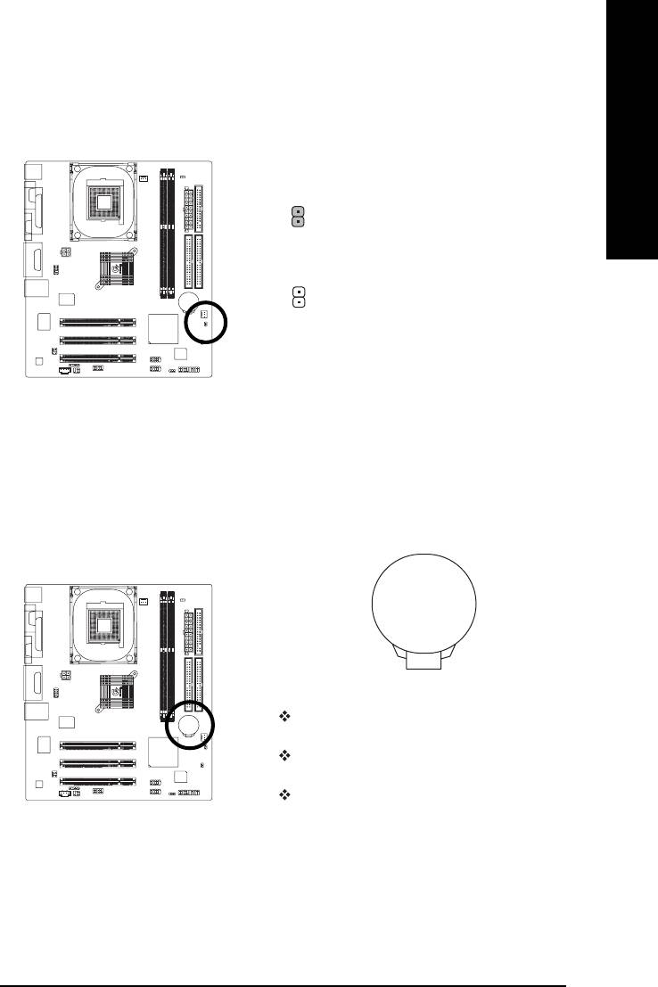
17) CI (CASE OPEN)
This 2-pin connector allows your system to enable or disable the "Case Open" item in BIOS, if the
system case begin remove.
Pin No. Definition
1 Signal
1
2 GND
- 26 -GA-8I845GV Series Motherboard
English
18) CLR_CMOS (Clear CMOS)
You may clear the CMOS data to its default values by this jumper. To clear CMOS, temporarily
shor 1-2 pin. Default doesn't include the "Shunter" to prevent from improper use this jumper.
1-2 close: Clear CMOS
1
Open: Normal
1
19) BAT (BATTERY)
+
CAUTION
Danger of explosion if battery is incorrectly
replaced.
Replace only with the same or equivalent type
recommended by the manufacturer.
Dispose of used batteries according to the
manufacturer's instructions.
If you want to erase CMOS...
1. Turn OFF the computer and unplug the power cord.
2. Remove the battery, wait for 30 second.
3. Re-install the battery.
4. Plug the power cord and turn ON the computer.
- 27 - Hardware Installation Process

English
- 28 -GA-8I845GV Series Motherboard


