Elica UP: инструкция
Раздел: Бытовая, кухонная техника, электроника и оборудование
Тип: Вытяжка
Инструкция к Вытяжке Elica UP

IT Istruzioni di montaggio e d'uso
EN Instruction on mounting and use
DE Montage- und Gebrauchsanweisung
FR Prescriptions de montage et mode d’emploi
NL Montagevoorschriften en gebruiksaanwijzingen
ES Montaje y modo de empleo
PT Instruções para montagem e utilização
EL ΟΔΗΓΙΕΣ ΣΥΝΑΡΜΟΛΟΓΗΣΗΣ ΚΑΙ ΧΡΗΣΗΣ
SV Monterings- och bruksanvisningar
FI Asennus- ja käyttöohjeet
NO Instrukser for montering og bruk
DA Bruger- og monteringsvejledning
PL Instrukcja montażu i obsługi
CS Návod na montáž a používání
SK Návod k montáži a užití
HU Felszerelési és használati utasítás
BG Инструкции за монтаж и употреба
RO INSTRUCTII DE MONTAJ SI FOLOSIRE
RU Инструкции по монтажу и эксплуатации
UK Інструкція з монтажу і експлуатації
ET Paigaldus- ja kasutusjuhend
LT montavimo ir naudojimosi instrukcija
LV ierīkošanas un izmantošanas instrukcija
SR Uputstva za montažu i upotrebu
SL Navodila za montažo in uporabo
HR Uputstva za montažu i za uporabu
TR Montaj ve kullanım talimatları
AR لﺎﻤﻌﺘﺳﻻاو ﺐﻴآﺮﺘﻟا قﺮﻃ
1 X
1 X
1 X
1 X
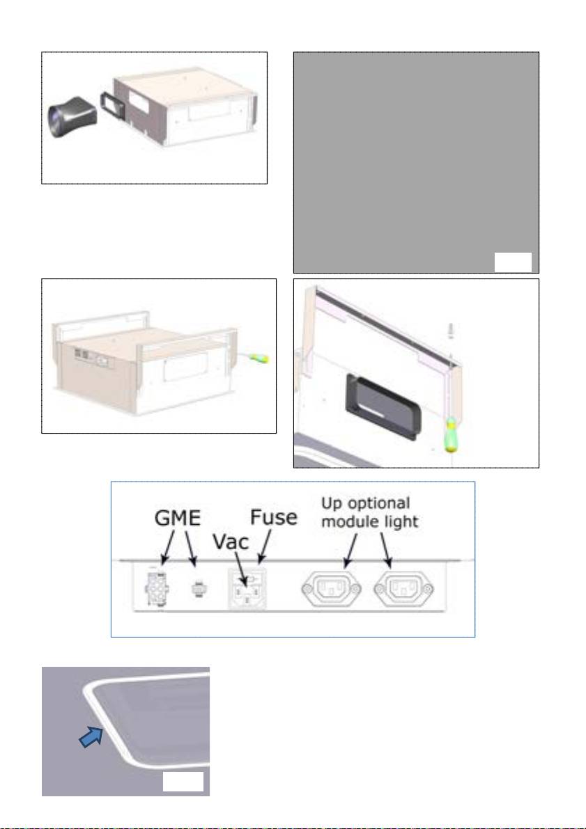
Fig.1
Fig.2
Fig.3
Fig.4
Fig. 5
Fig. 6
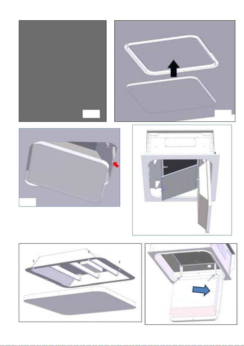
Fig. 7 Fig. 8
Fig. 9
Fig. 10
Fig. 11
Fig. 12
IT - Istruzioni di montaggio e d'uso
Attenersi strettamente alle istruzioni riportate in questo
comunque quanto espressamente indicato nelle istruzioni di
manuale. Si declina ogni responsabilità per eventuali
manutenzione riportate in questo manuale).
inconvenienti, danni o incendi provocati all'apparecchio
L’inosservanza delle norme di pulizia della cappa e della
derivati dall'inosservanza delle istruzioni riportate in questo
sostituzione e pulizia dei filtri comporta rischi di incendi.
manuale. La cappa è concepita per l'aspirazione dei fumi e
Non utilizzare o lasciare la cappa priva di lampade
vapori della cottura ed è destinata al solo uso domestico.
correttamente montate per possibile rischio di scossa elettrica.
La cappa può avere estetiche differenti rispetto a quanto
Si declina ogni responsabilità per eventuali inconvenienti,
illustrato nei disegni di questo libretto, comunque le
danni o incendi provocati all’apparecchio derivati
istruzioni per l'uso, la manutenzione e l'installazione
dall’inosservanza delle istruzioni riportate in questo manuale.
rimangono le stesse.
Questo apparecchio è contrassegnato in conformità alla
! E' importante conservare questo manuale per poterlo
Direttiva Europea 2002/96/EC, Waste Electrical and Electronic
consultare in ogni momento. In caso di vendita, di
Equipment (WEEE). Assicurandosi che questo prodotto sia
cessione o di trasloco, assicurarsi che resti insieme al
smaltito in modo corretto, l'utente contribuisce a prevenire le
prodotto.
potenziali conseguenze negative per l'ambiente e la salute.
! Leggere attentamente le istruzioni: ci sono importanti
informazioni sull'installazione, sull'uso e sulla sicurezza.
! Non effettuare variazioni elettriche o meccaniche sul
Il simbolo
sul prodotto o sulla documentazione di
prodotto o sulle condotte di scarico.
accompagnamento indica che questo prodotto non deve
essere trattato come rifiuto domestico ma deve essere
Avvertenze
consegnato presso l'idoneo punto di raccolta per il riciclaggio
Attenzione! Non collegare l’apparecchio alla rete elettrica
di apparecchiature elettriche ed elettroniche. Disfarsene
finche l’installazione non è totalmente completata.
seguendo le normative locali per lo smaltimento dei rifiuti. Per
Prima di qualsiasi operazione di pulizia o manutenzione,
ulteriori informazioni sul trattamento, recupero e riciclaggio di
disinserire la cappa dalla rete elettrica togliendo la spina o
questo prodotto, contattare l'idoneo ufficio locale, il servizio di
staccando l’interruttore generale dell’abitazione.
raccolta dei rifiuti domestici o il negozio presso il quale il
Per tutte le operazioni di installazione e manutenzione
prodotto è stato acquistato.
utilizzare guanti da lavoro
L’apparecchio non è destinato all’utilizzo da parte di bambini o
persone con ridotte capacità fisiche sensoriali o mentali e con
mancata esperienza e conoscenza a meno che essi non siano
sotto la supervisione o istruiti nell’uso dell’apparecchiatura da
una persona responsabile per la loro sicurezza.
I bambini devono essere controllati affinché non giochino con
l’apparecchio.
Mai utilizzare la cappa senza griglia correttamente montata!
La cappa non va MAI utilizzata come piano di appoggio a
meno che non sia espressamente indicato.
Il locale deve disporre di sufficiente ventilazione, quando la
cappa da cucina viene utilizzata contemporaneamente ad altri
apparecchi a combustione di gas o altri combustibili.
L’aria aspirata non deve essere convogliata in un condotto
usato per lo scarico dei fumi prodotti da apparecchi a
combustione di gas o di altri combustibili.
E’ severamente vietato fare cibi alla fiamma sotto la cappa.
L’impiego di fiamma libera è dannoso ai filtri e può dar luogo
ad incendi, pertanto deve essere evitato in ogni caso.
La frittura deve essere fatta sotto controllo onde evitare che
l’olio surriscaldato prenda fuoco.
Quando il piano di cottura è in funzione le parti accessibili
della cappa possono diventare calde.
Per quanto riguarda le misure tecniche e di sicurezza da
adottare per lo scarico dei fumi attenersi strettamente a
quanto previsto dai regolamenti delle autorità locali
competenti.
La cappa va frequentemente pulita sia internamente che
esternamente (ALMENO UNA VOLTA AL MESE, rispettare
5
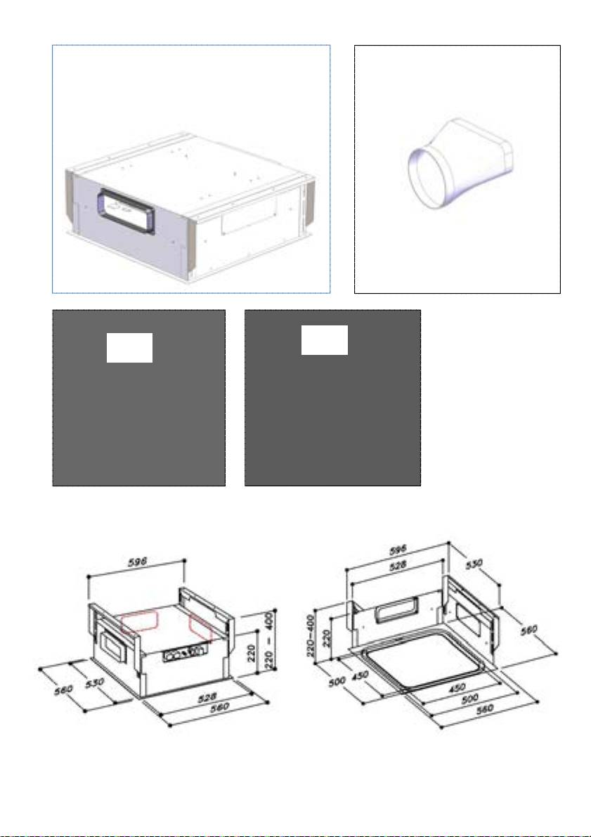
Regolare l’escursione delle staffe di fissaggio in funzione della
Utilizzazione
profondità della nicchia; min. 220mm max 400mm come da
La cappa è realizzata per essere utilizzata in versione
fig. 3. Serrare in maniera robusta le viti di fissaggio delle staffe
aspirante ad evacuazione esterna o filtrante a ricircolo interno.
appena regolate.
Collocare la cappa nella posizione stabilita e fissarla mediante
le viti in dotazione, vedi fig.4.
Versione aspirante
Effettuare le forature al soffitto in corrispondenza dei fori
I vapori vengono evacuati verso l’esterno tramite un tubo di
centrali delle staffe e fissare definitivamente il prodotto
scarico fissato alla flangia di raccordo del gruppo aspirante
mediante l’applicazione delle restanti viti.
(motore remoto).
Effettuare il collegamento elettrico (vedi fig. 5) e collegare il
tubo di evacuazione dell’aria seguendo le indicazioni riportate
nell’apposito capitolo SISTEMI DI CANALIZZAZIONE.
Versione filtrante
L’aria aspirata verrà sgrassata e deodorata prima di essere
Nel caso di installazione di UP OPTIONAL MODULE LIGHT
riconvogliata nella stanza. Per utilizzare la cappa in questa
collegare il cavo delle cappe satellite ai connettori indicati in
versione è necessario installare un sistema di filtraggio
figura 5.
aggiuntivo a base di carboni attivi.
Installare la lastra in cartongesso facendo attenzione che
Installazione
aderisca perfettamente al bordo in metallo della cappa come
Per l’installazione del prodotto sono richieste due
da figura 6.
persone.
La foratura da fare nella lastra in cartongesso è delle
dimensioni pari a 502 mm X 502 mm con R71 in
Il prodotto è privo del motore di aspirazione, pertanto
corrispondenza degli angoli, utilizzare la maschera di foratura
deve essere abbinato ad un gruppo aspirante (motore
fornita in dotazione.
remoto) dello stesso produttore.
Per fissare il cartongesso alla cappa utilizzare le viti fornite in
Per installare il prodotto è necessario realizzare un
dotazione nei punti indicati in fig. 7, vedi maschera di foratura
controsoffitto della profondità minima di almeno 220 mm fino
fornita in dotazione.
ad un massimo di 400 mm. Per profondità superiori occorre
Installare le viti fornite in dotazione 3.5x22. Consigliamo di
richiedere l’apposito KIT con staffe di installazione per
utilizzare almeno 12 viti per ottenere un buon fissaggio.
controsoffitti con profondità da 400mm a 580mm.
Nel caso in cui la cappa sia dotata di pannello interno da
E’ possibile scegliere il lato della cappa dal quale far defluire
rivestire in cartongesso, legno o altro materiale, realizzare una
l’aria aspirata, sono presenti uscite aria di forma rettangolare
lastra delle seguenti dimensioni: 448mm X 448mm con R49
su tre lati della cappa.
in corrispondenza degli angoli, vedi maschera di foratura
Dopo aver scelto la posizione migliore, predisporre la
fornita in dotazione.
canalizzazione; la fornitura in dotazione
Installare la lastra al pannello (fig.8), utilizzando le viti in
comprende un flangia uscita aria di forma rettangolare
dotazione in caso di cartongesso oppure, utilizzando del
230x80mm da installare sull’uscita prescelta.
collante adeguato relativamente al tipo di materiale da fissare.
Lasciare chiusi i fori di evacuazione aria non utilizzati.
Attenzione: non usare viti con lunghezza superiore allo
In dotazione viene fornito anche un raccordo che permette
spessore del pannello, massimo 3.5x22.
l’utilizzo dei tubi con diametro pari 150mm (vedi fig.1), nel
caso si intenda realizzare un condotto uscita aria circolare.
Apertura pannello
L’apertura del pannello avviene tirandolo dal lato opposto
Individuare nel soffitto solido un riferimento rispetto al centro
alle cerniere, in corrispondenza del led che indica le velocità
esatto di installazione della cappa (vedi fig. 2), tracciare quindi
del motore di aspirazione (fig. 9).
i riferimenti per le forature da effettuare secondo le quote
Accompagnare il pannello con le mani durante l’apertura.
indicate in fig. 2.
A seguito dell’apertura pannello è possibile accedere al filtro
antigrasso e dopo la rimozione del filtro antigrasso, agendo
Effettuare le forature nel soffitto solido utilizzando un punta
nell’apposita maniglia, è possibile raggiungere la sede del
elicoidale adeguata da diametro 8mm ed inserire i tasselli
filtro carbone (fig. 10).
forniti in dotazione, è sufficiente effettuare le forature esterne
Per chiudere il pannello è sufficiente riportarlo in posizione
indicate in figura 2, quelle interne vanno fatte
orizzontale fino a quando avviene l’aggancio automaticamente
successivamente all’installazione della cappa.
della chiusura.
6

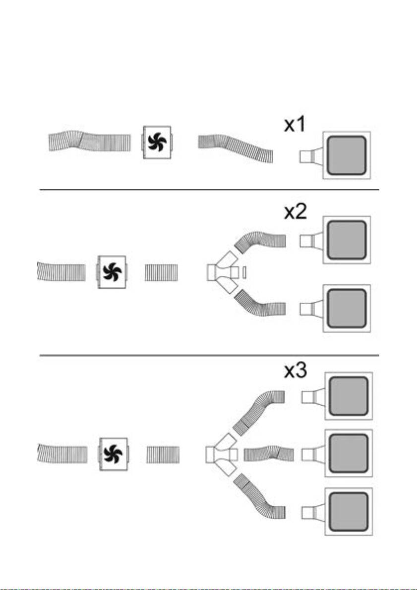
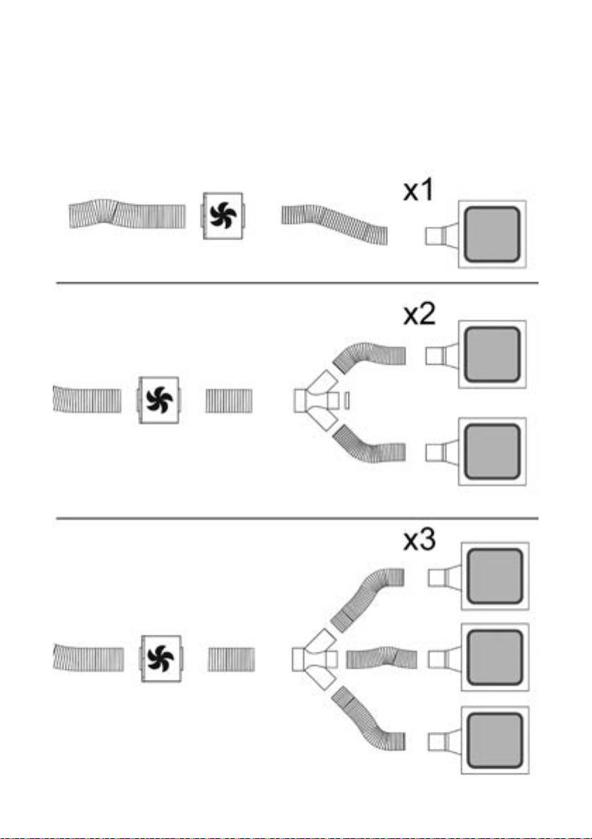
Sistemi di canalizzazione
E’ possibile installare una cappa ”UP” con ulteriori uno o due optional module in un unico sistema di aspirazione, quindi collegate ad
un solo motore aspirante remoto interno o esterno all’abitazione.
Un sistema di aspirazione, formato da più elementi, viene gestito da un unico telecomando in quanto solo una cappa (UP) dispone di
tutti i componenti elettronici necessari al funzionamento, mentre i restanti UP OPTIONAL MODULE, sono dipendenti alla cappa
principale UP.
I collegamenti tra la cappa principale (UP) e i restanti UP OPTIONAL MODULE dovranno essere realizzati nelle seguenti modalità:
7
La velocità di aspirazione impostata viene indicata
Collegamento Elettrico
mediante il led presente nel canale perimetrale di
L’allacciamento della cappa alla rete elettrica deve essere
aspirazione (Fig.9).
effettuato da personale tecnico qualificato e specializzato.
Ad ogni colore generato dal led, corrisponde una
La tensione di rete deve corrispondere alla tensione riportata
determinata velocità come indicato sotto:
sull’etichetta caratteristiche situata all’interno della cappa. Se
Prima velocità colore BIANCO
provvista di spina allacciare la cappa ad una presa conforme
Seconda velocità colore AZZURRO
alle norme vigenti posta in zona accessibile anche dopo
Terza velocità colore BLU
l’installazione. Se sprovvista di spina (collegamento diretto
Quarta velocità colore ROSSO
alla rete) o la spina non è posta in zona accessibile, anche
dopo installazione, applicare un interruttore bipolare a norma
Controllo della luce:
che assicuri la disconnessione completa della rete nelle
Premere il tasto "◄" o il tasto "►" sino a visualizzare sul
condizioni della categoria di sovratensione III, conformemente
alle regole di installazione.
telecomando il simbolo
Attenzione! Prima di ricollegare il circuito della cappa
La luce centrale può essere accesa e spenta in due modi:
all’alimentazione di rete e di verificarne il corretto
1. Premere il tasto “+” o il tasto “-” rispettivamente per
funzionamento, controllare sempre che il cavo di rete sia stato
accendere (ON) o spegnere (OFF) la luce centrale.
montato correttamente.
2. Premere il tasto "■" per cambiare lo stato della luce da
Attenzione! La sostituzione del cavo di alimentazione deve
spenta (OFF) ad accesa (ON) o viceversa.
essere effettuata dal servizio assistenza tecnica autorizzato o
da persona con qualifica similare.
Reset e configurazione della segnalazione di saturazione
dei filtri
Montaggio
Accendere la cappa ad una qualsiasi velocità (vedi paragrafo
Prima di procedere nell’installazione dell’apparecchio
sopra “Selezione delle velocità (potenze) di aspirazione”)
verificare che tutti i componenti non siano danneggiati, in caso
Premere il tasto "◄" o il tasto "►" sino a visualizzare sul
contrario contattare il rivenditore e non proseguire con
l’installazione. Inoltre leggere attentamente tutte le istruzioni
telecomando il simbolo
di seguito riportate.
Premere contemporaneamente per più di 3 secondi i tasti “+”
e “-”, tutti i led delle velocità (potenze) di aspirazione smettono
Funzionamento
di lampeggiare ad indicare che il reset della segnalazione è
Usare la velocità maggiore in caso di particolare
stato eseguito.
concentrazione di vapori di cucina. Consigliamo di accendere
l'aspirazione 5 minuti prima di iniziare a cucinare e di lasciarla
Manutenzione del telecomando
in funzione a cottura terminata per altri 15 minuti circa.
Per il corretto utilizzo leggere attentamente le istruzioni
Pulizia del telecomando:
sottostanti.
Pulire il telecomando con un panno morbido ed una soluzione
detergente neutra priva di sostanze abrasive
Uso del telecomando
Sostituzione della batteria:
il telecomando è in grado di controllare tutte le funzionalità
• Aprire il vano della batteria facendo leva con un piccolo
della cappa:
cacciavite a punta piatta.
• Sostiutire la batteria esausta con una nuova da 12 V tipo
Selezione delle velocità (potenze) di aspirazione
MN21/23
Controllo della luce
Nell' inserire la nuova batteria rispettare le polarità
indicate nel vano della batteria!
Tasto senza funzioni
• Richiudere il vano della batteria.
Smaltimento delle batterie
Reset e configurazione della segnalazione di
Lo smaltimento delle batterie deve essere svolto in accordo
saturazione dei filtri
con tutte le normative e leggi nazionali. Non smaltite le
batterie usate assieme ai rifiuti normali.
Selezione delle velocità (potenze) di aspirazione:
Le batterie devono essere smaltite in modo sicuro.
Premere il tasto "◄" o il tasto "►" sino a visualizzare sul
Per maggiori ragguagli circa gli aspetti di protezione
dell'ambiente, il riciclaggio e lo smaltimento di batterie,
telecomando il simbolo ”
contattate gli uffici incaricati della raccolta differenziata.
Premere il tasto “+” o il tasto “-” o il tasto "■" rispettivamente
per aumentare o diminuire o spegnere la velocità (potenza) di
aspirazione.
8

Anomalie di funzionamento
Filtro antigrasso
Trattiene le particelle di grasso derivanti dalla cottura.
La cappa non funziona
Deve essere pulito una volta al mese (o quando il sistema di
Verificate che:
indicazione di saturazione dei filtri - se previsto sul modello in
• Non vi sia un blackout di corrente
possesso- indica questa necessità), con detergenti non
• Sia stata effettivamente selezionata una certa velocità.
aggressivi, manualmente oppure in lavastoviglie a basse
• Il tasto rosso di reset posizionato sopra ai filtri all’interno
temperature ed a ciclo breve.
della cappa, sia premuto.
Con il lavaggio in lavastoviglie il filtro antigrasso metallico può
scolorirsi ma le sue caratteristiche di filtraggio non cambiano
La cappa ha un rendimento scarso
assolutamente.
Verificate che:
Il montaggio e smontaggio dei filtri antigrasso avviene
• La velocità motore selezionata sia sufficiente per la
aprendo il pannello come indicato nel capitolo: "Apertura
quantità di fumi e di vapori presenti
pannello".
• La cucina sia areata sufficientemente da permettere una
presa d’aria il filtro carbone non sia usurato (cappa in
Filtro ai carboni attivi (Solo per Versione Filtrante)
versione filtrante).
Trattiene gli odori sgradevoli derivanti dalla cottura.
• Il tubo di scarico uscita aria sia privo di ostruzioni.
La saturazione del filtro carbone si verifica dopo un uso più o
meno prolungato a seconda del tipo di cucina e della
Manutenzione
regolarità della pulizia del filtro grassi. In ogni caso è
Attenzione! Prima di qualsiasi operazione di pulizia o
necessario sostituire la cartuccia al massimo ogni quattro
manutenzione, disinserire la cappa dalla rete elettrica
mesi.
togliendo la spina o staccando l’interruttore generale
NON può essere lavato o rigenerato
dell’abitazione o premendo il tasto rosso presente
all’interno della cappa, sopra ai filtri antigrasso.
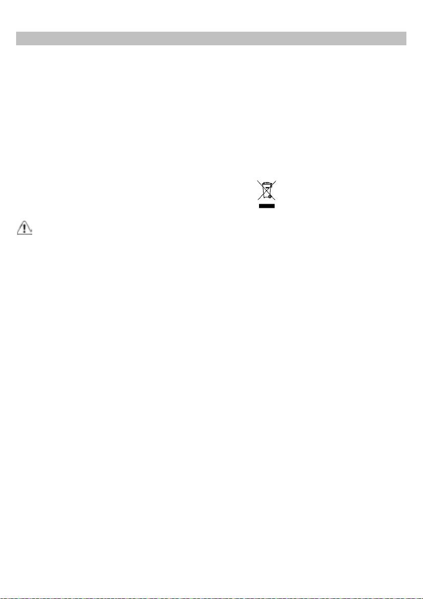
Sostituzione Lampade
Disinserire l’apparecchio dalla rete elettrica.
Pulizia
Attenzione! Prima di toccare le lampade sincerarsi che siano
La cappa va frequentemente pulita (almeno con la stessa
fredde.
frequenza con cui si esegue la manutenzione dei filtri grassi),
sia internamente che esternamente. Per la pulizia usare un
Per sostituire le lampade fluorescenti danneggiate occorre
panno inumidito con detersivi liquidi neutri.
scollegare il prodotto dalla rete elettrica quindi, aprire il
Evitare l’uso di prodotti contenenti abrasivi. NON UTILIZZARE
panello seguendo le indicazioni riportate nel capitolo
ALCOOL!
“APERTURA PANNELLO”.
Attenzione: L’inosservanza delle norme di pulizia
Rimuovere le sei viti perimetrali del pannello ed aprirlo come
dell’apparecchio e della sostituzione dei filtri comporta rischi di
da figura 11; procedere nella sostituzione della lampada
incendi. Si raccomanda quindi di attenersi alle istruzioni
fluorescente utilizzando una lampada con stesse
suggerite.
caratteristiche.
Si declina ogni responsabilità per eventuali danni al motore,
Ripristinare il pannello e le viti rimosse in precedenza.
incendi provocati da un’impropria manutenzione o
dall’inosservanza delle suddette avvertenze.
Per la sostituzione dell’alimentatore delle lampade fluorescenti
agire analogamente a come descritto sopra, in quanto
Pannello
l’alimentatore è posizionato accanto le lampade.
Sostituzione pannello
Se l'illuminazione non dovesse funzionare, controllate il
La sostituzione del pannello avviene in primo luogo aprendolo
corretto inserimento delle lampade nella sede prima di
come indicato nel capitolo apertura pannello, nel caso di
chiamare l'assistenza tecnica.
pannello LIGHT occorre togliere alimentazione al prodotto e
scollegare il cavo di alimentazione delle lampade agendo nel
connettore elettrico presente immediatamente sopra al
pannello.
Rimuovere i due dadi autobloccanti di fissaggio del pannello
(vedi fig. 12) e facendo scorrere il pannello verso destra
rimuoverlo dalla sua sede. Per ripristinare il pannello seguire
la procedura sopra descritta nel verso contrario.
9
EN - Instruction on mounting and use
Closely follow the instructions set out in this manual. All
adopted for fume discharging it is important to closely follow
responsibility, for any eventual inconveniences, damages or
the regulations provided by the local authorities.
fires caused by not complying with the instructions in this
The hood must be regularly cleaned on both the inside and
manual, is declined. The hood is conceived for the suction of
outside (AT LEAST ONCE A MONTH).
cooking fumes and steam and is destined only for domestic
This must be completed in accordance with the maintenance
use.
instructions provided in this manual). Failure to follow the
The hood can look different to that illustrated in the
instructions provided in this user guide regarding the cleaning
drawings in this booklet. The instructions for use,
of the hood and filters will lead to the risk of fires.
maintenance and installation, however, remain the same.
Do not use or leave the hood without the lamp correctly
! It is important to conserve this booklet for consultation at
mounted due to the possible risk of electric shocks.
any moment. In the case of sale, cession or move, make
We will not accept any responsibility for any faults, damage or
sure it is together with the product.
fires caused to the appliance as a result of the non-
! Read the instructions carefully: there is important
observance of the instructions included in this manual.
information about installation, use and safety.
This appliance is marked according to the European directive
! Do not carry out electrical or mechanical variations on the
2002/96/EC on Waste Electrical and Electronic Equipment
product or on the discharge conduits.
(WEEE). By ensuring this product is disposed of correctly, you
will help prevent potential negative consequences for the
Caution
environment and human health, which could otherwise be
WARNING! Do not connect the appliance to the mains until
caused by inappropriate waste handling of this product.
the installation is fully complete.
Before any cleaning or maintenance operation, disconnect
hood from the mains by removing the plug or disconnecting
The symbol
on the product, or on the documents
the mains electrical supply.
accompanying the product, indicates that this appliance may
Always wear work gloves for all installation and maintenance
not be treated as household waste. Instead it should be taken
operations.
to the appropriate collection point for the recycling of electrical
The appliance is not intended for use by children or persons
and electronic equipment. Disposal must be carried out in
with impaired physical, sensorial or mental faculties, or if
accordance with local environmental regulations for waste
lacking in experience or knowledge, unless they are under
disposal.
supervision or have been trained in the use of the appliance
For further detailed information regarding the process,
by a person responsible for their safety.
collection and recycling of this product, please contact the
This appliance is designed to be operated by adults, children
appropriate department of your local authorities or the local
should be monitored to ensure that they do not play with the
department for household waste or the shop where you
appliance.
purchased this product.
This appliance is designed to be operated by adults. Children
Additional Installation Specifications:
should not be allowed to tamper with the controls or play with
Use only the fixing screws supplied with the product for
the appliance.
installation.
Never use the hood without effectively mounted grating!
Use the correct length screws which are identified in the
The hood must NEVER be used as a support surface unless
Installation Guide
specifically indicated.
WARNING! Failure to install the screws or fixing device in
The premises where the appliance is installed must be
accordance with these instructions may result in electrical
sufficiently ventilated, when the kitchen hood is used together
hazards.
with other gas combustion devices or other fuels.
The ducting system for this appliance must not be connected
to any existing ventilation system which is being used for any
other purpose such as discharging exhaust fumes from
appliances burning gas or other fuels.
The flaming of foods beneath the hood itself is severely
prohibited.
The use of exposed flames is detrimental to the filters and
may cause a fire risk, and must therefore be avoided in all
circumstances.
Any frying must be done with care in order to make sure that
the oil does not overheat and ignite.
Accessible parts of the hood may became hot when used with
cooking appliance.
With regards to the technical and safety measures to be
10
Fig. 3. Tighten strongly the fastening screws of the brackets
Use
immediately after you placed them into position.
The hood is designed to be used either for exhausting or filter
version.
Place the hood in the required position and secure it with the
screws provided; see fig.4.
Perform the holes into the ceiling in correspondence of the
central holes of the brackets and fix definitively the product by
Ducting version
applying the remaining screws.
The vapours are evacuated outside through an exhaust duct
fixed to the connection flange of the suction unit (remote
Make the electrical connection (see fig. 5) and connect the air
motor).
discharge pipe following the instructions given in the related
section DUCTING SYSTEMS.
In case of installation of UP OPTIONAL MODULE LIGHT
Filter version
connect the cable of the satellite hoods to the connectors
One active charcoal filter is needed for this and can be
shown in Figure 5.
obtained from your usual retailer.
The filter removes the grease and smells from the extracted
Install the plasterboard sheet making sure that it fits perfectly
air before sending it back into the room through the upper
to the metal edge of the hood as shown in figure 6.
outlet grid.
The drilling to be done in plasterboard sheet has the size of
502 mm X 502 mm with R71 on the corners; use the drilling
Installation
template supplied.
Two persons are needed for the installation of this
product.
To attach the plasterboard to the hood, use the screws
provided in the locations indicated in Fig. 7; see the supplied
The product is not equipped with the duction motor,
drilling template.
therefore it must be coupled to a suction unit (remote
Install the supplied screws 3.5x22. We recommend at least 12
motor) of the same manufacturer.
screws to obtain a good fixation.
To install the product is necessary to make a countertop
In case the hood is provided with an internal panel be covered
minimum depth of at least 220 mm up to a maximum of 400
in plasterboard, wood or other material, make a sheet of the
mm.For greater depths it is necessary to ask the special KIT
following dimensions: 448mm X 448mm with R49 on the
with mounting brackets for ceiling depth from 400mm to
corners; see drilling template supplied.
580mm.
Install the sheet to the panel (fig. 8), using the screws
provided in the case of plasterboard or using the appropriate
You can choose the side of the hood from which to run off the
adhesive for the type of material to be secured.
sucked air; there are air outlets of rectangular shape on three
Caution: Do not use screws longer than the panel
sides of the hood.
thickness, maximum 3.5x22.
After choosing the best location, set up the channel, the
supply provided includes an air outlet flange of rectangular
Panel opening
shape 230x80mm to be installed on the chosen outlet. Leave
The opening of the panel can be done by pulling on the side
closed the air exhaust holes are not used. There is also a
opposite the hinges, in correspondence of the LED that
fitting included, that allows the use of tubes with a diameter
indicates the speed of the suction motor (fig. 9). Accompany
equal to 150 mm (see fig. 1), if you plan to create a circular air
the panel with your hands during the opening.
outlet duct.
Following the panel opening, you can access the grease filter
and after its removal, acting on the appropriate handle, you
Locate on the ceiling a solid reference from the exact center of
can reach the seat of the charcoal filter (fig. 10).
installation of the hood (see Fig. 2), and then trace the
To close the panel, simply bring it in horizontal position until it
references for the drilling to be carried out in accordance with
the automatic closing coupling occurs.
the dimensions shown in Fig. 2.
Perform the holes into the ceiling using a suitable solid twist
drill of 8mm and insert the anchors supplied; it is enough to
perform the external punctures indicated in Figure 2, the
internal ones should be done after you install the hood.
Adjust the excursion of the fixing brackets according to the
depth of the niche; min. 220mm, max. 400mm as, shown in
11
Ducting systems
It is possible to install an "UP" extractor hood with one or two additional optional modules in a single suction system, thus to connect
it to a single remote suction motor inside or outside the house.
A suction system, consisting of several elements, is operated by a single remote control as only a hood (UP) has all the electronic
components needed for the operation, while the remaining UP
OPTIONAL MODULE are dependent to the main UP hood.
The connections between the main hood (UP) and the remaining UP OPTIONAL MODULE must be made in the following ways:
12
Fourth speed RED
Electrical connection
The hood must be connected to the mains supply by qualified
Light control:
and trained technicians.
Press key "◄" or "►" until the remote control displays the
The mains power supply must correspond to the rating
indicated on the plate situated inside the hood. If provided with
symbol
a plug connect the hood to a socket in compliance with current
The central light can be switched on and off in two ways:
regulations and positioned in an accessible area, after
1. Press key “+” or “-” respectively to switch on (ON) or off
installation. If it not fitted with a plug (direct mains connection)
(OFF) the central light.
or if the plug is not located in an accessible area, after
2. Press key "■" to change the light state from off (OFF) to
installation, apply a double pole switch in accordance with
on (ON) or viceversa.
standards which assures the complete disconnection of the
mains under conditions relating to over-current category III, in
Reset and configuration of the filter saturation signal
accordance with installation instructions.
Switch on the hood at any speed (see paragraph above
Warning! Before re-connecting the hood circuit to the mains
“Selection of the suction speeds (powers)”)
supply and checking the efficient function, always check that
Press key "◄" or "►" until the remote control displays the
the mains cable is correctly assembled.
Warning! Power cable replacement must be undertaken by
symbol
the authorised service assistance centre or similar qualified
person.
Press keys “+” and “-“ contemporaneously for more than 3
seconds, all the suction speed LEDs (powers) stop flashing,
Mounting
showing that the reset of the signal has been carried out.
Before starting to mount the appliance, make sure that no
component is damaged, otherwise contact the dealer and stop
Maintenance of the remote control
mounting. In addition, read all the instructions below carefully.
Cleaning the remote control:
Clean the remote control with a damp cloth and a neutral
Operation
solution of detergent without abrasive substances.
Use the high suction speed in cases of concentrated kitchen
vapours. It is recommended that the cooker hood suction is
Changing the battery:
switched on for 5 minutes prior to cooking and to leave in
• Open the battery casing using a small screwdriver with a
flat point.
operation during cooking and for another 15 minutes
• Change the finished battery with a new one of 12 V type
approximately after terminating cooking.
MN21/23
For the correct use please carefully read the intructions below.
In inserting the new battery respect the polarity indicated
on the battery casing!
Use of the remote control
• Close the battery casing up again.
Disposal of the batteries
the remote control can control all the functions of the hood:
Ultimate disposal of the batteries should be handled according
to all national laws and regulations. Do not place used
Selection of the suction speeds (powers)
batteries in your regular waste. Ultimate disposal of the
Control of the light
batteries must be done safely. Contact your local waste
management officials for other information regarding the
Key without functions
environmentally sound collection, recycling, and disposal of
the batteries.
Operation anomalies
Reset and configuration of the filter saturation signal
The hood does not work
Selection of the suction speeds (powers):
Make sure that:
Press key "◄" or "►" until the following symbol is displayed
• There is no current blackout
• A speed has been effectively selected.
on the remote control: ”
• The red reset button located above the filters inside the
Press key “+” or “-” or "■" respectively to increase or reduce or
hood is pressed.
switch off the suction speed (power).
The set suction speed is indicated by the LED in the suction
The hood has low efficiency
perimeter channel (Fig.9).
Make sure that:
To each color generated by the LED, it corresponds a specific
• The motor speed selected is sufficient for the quantity of
fumes present
speed, as shown below:
• The kitchen is aired enough to allow an air intake and the
First speed WHITE
charcoal filter is not worn out (filter version hood).
Second speed BLUE
• The air outlet pipe is not clogged.
Third speed DARK BLUE
13

Maintenance
Charcoal filter (filter version only)
Warning! Before any cleaning or maintenance operation,
It absorbs unpleasant odours caused by cooking.
disconnect the hood from the mains by removing the plug
The saturation of the charcoal filter occurs after more or less
or disconnecting the main switch of the house, or by
prolonged use, depending on the type of cooking and the
pressing the red button inside the hood, above the grease
regularity of cleaning of the grease filter.
filters.
In any case it is necessary to replace the cartridge at least
every four mounths.
Cleaning
The charcoal filter may NOT be washed or regenerated.
The cooker hood should be cleaned regularly (at least with the
same frequency with which you carry out maintenance of the
Replacing lamps
fat filters) internally and externally. Clean using the cloth
Disconnect the hood from the electricity.
dampened with neutral liquid detergent. Do not use abrasive
Warning! Prior to touching the light bulbs ensure they are
products. DO NOT USE ALCOHOL!
cooled down.
WARNING: Failure to carry out the basic cleaning
recommendations of the cooker hood and replacement of the
To replace the damaged fluorescent lamps you must unplug
filters may cause fire risks.
the product from the mains, then open the panel by following
Therefore, we recommend observing these instructions.
the instructions in the chapter "PANEL OPENING".
The manufacturer declines all responsibility for any damage to
Remove the six perimeter screws of the panel and open it as
the motor or any fire damage linked to inappropriate
shown in figure 11; proceed in replacing the fluorescent lamp
maintenance or failure to observe the above safety
using a lamp with the same characteristics.
recommendations.
Put back into position the panel and the screws you previously
removed.
Panel
For the replacement of the fluorescent lamps feeder, act in the
Panel replacement
same way as described above, since the feeder is positioned
The panel replacement is done by first opening it as indicated
next to the lamps.
in chapter opening panel; in the case of the LIGHT panel, you
must disconnect the power from the mains and unplug the
If the lights do not work, make sure that the lamps are fitted
power cord of the lamps by acting on the electrical connector
properly into their housings before you call for technical
located right above the panel.
assistance.
Remove the two locknuts securing the panel (see fig. 12) and
slide the panel to the right to remove it from its seat.
To place the panel back into position, follow the above
described procedure in reverse order.
Grease filter
Traps cooking grease particles.
This must be cleaned once a month (or when the filter
saturation indication system – if envisaged on the model in
possession – indicates this necessity) using non aggressive
detergents, either by hand or in the dishwasher, which must
be set to a low temperature and a short cycle.
When washed in a dishwasher, the grease filter may discolour
slightly, but this does not affect its filtering capacity.
The grease filters installation and removal is done by opening
the panel as described in section "Panel Opening."
14
DE - Montage- und Gebrauchsanweisung
Die Instruktionen, die in diesem Handbuch gegeben
Flamme zu kochen.
werden, müssen strikt eingehalten werden. Es wird
Eine offene Flamme beschädigt die Filter und kann Brände
keinerlei Haftung übernommen für mögliche Mängel, Schäden
verursachen, daher ist dies in jedem Fall zu vermeiden.
oder Brände der Dunstabzugshaube, die auf die
Das Frittieren muss unter Aufsicht erfolgen, um zu vermeiden,
Nichtbeachtung der Vorschriften in diesem Handbuch
dass das überhitzte Öl Feuer fängt.
zurückzuführen sind. Die Dunstabzugshaube ist fuer die
Zugängliche Teile können beim Gebrauch mit Kochgeräten
Absaugung der Kochduenste und Verbrennungsgase, die
heiss werden.
waehrend des Kochvorgangs entstehen , entwickelt. Sie ist
In Bezug auf technische und Sicherheitsmaßnahmen für die
nur zum Hausgebrauch geeignet.
Ableitung der Abluft sind die Vorschriften der zuständigen
Der Dunstabzugshaube kann von der aesthetischen Seite
örtlichen Behörden strengstens einzuhalten.
her ander sein als die Zeichnungen die in diesem
Die Haube muss regelmäßig innen und außen gereinigt
Bedienungsanleitung geschrieben sind.
werden (MINDESTENS EINMAL IM MONAT, diesbezüglich
Die Bedienungsanleitungen , die Wartung und die
sind in jedem Fall die ausdrücklichen Angaben in der
Installation sind aber gleich.
Wartungsanleitung dieses Handbuchs zu beachten).
! Es ist wichtig diese Bedienungsanleitung zu behalten um
Eine Nichtbeachtung der Vorschriften zur Reinigung der
sie in jedem Moment nachzuschlagen. Im Fall von
Haube sowie zur Auswechselung und Reinigung der Filter
Verkaufen, Abtretung oder Umziehen, versichern Sie sich
führt zu Brandgefahr.
bitte dass Sie mit dem Produkt zusammen bleibt.
Um das Risiko eines Stromschlages zu vermeiden, darf die
! Die Bedienungsanleitungen richtig lesen: es gibt
Dunstabzugshaube ohne richtig eingesetzte Lampen nicht
wichtige Informationen ueber die Installation, Benutzen
betrieben werden.
und Sicherheit.
Es wird keinerlei Haftung übernommen für Fehler, Schäden
! Führen Sie keine elektrische oder mechanische
oder Brände des Gerätes, die durch Nichteinhaltung der in
Aenderungen am Produkt oder an den Abgasrohren vor.
diesem Handbuch aufgeführten Anweisungen verschuldet
wurden.
Warnung
In Übereinstimmung mit den Anforderungen der Europäischen
Achtung! Das Gerät nicht an das Stromnetz anschließen,
Richtlinie 2002/96/EG über Elektro- und Elektronik-Altgeräte
solange die Installation noch nicht abgeschlossen ist.
(WEEE) ist vorliegendes Gerät mit einer Kennzeichnung
Vor Beginn sämtlicher Reinigungs- oder Wartungsarbeiten
versehen.
muss das Gerät durch Ziehen des Steckers oder Betätigen
Sie leisten einen positiven Beitrag für den Schutz der Umwelt
des Hauptschalters der Wohnung vom Stromnetz getrennt
und die Gesundheit des Menschen, wenn Sie dieses Gerät
werden.
einer gesonderten Abfallsammlung zuführen. Im unsortierten
Bei allen Installations- und Instandhaltungsarbeiten immer
Siedlungsmüll könnte ein solches Gerät durch unsachgemäße
Schutzhandschuhe tragen.
Entsorgung negative Konsequenzen nach sich ziehen.
Kinder nicht mit dem Gerät spielen lassen.
Auf dem Produkt oder der beiliegenden
Erwachsene und Kinder dürfen nie unbeaufsichtigt das Gerät
betreiben,
– wenn sie körperlich oder geistig dazu nicht in der Lage sind,
Produktdokumentation ist folgendes Symbol
einer
– oder wenn ihnen Wissen und Erfahrung fehlen, das Gerät
durchgestrichenen Abfalltonne abgebildet. Es weist darauf
richtig und sicher zu bedienen.
hin, dass eine Entsorgung im normalen Haushaltsabfall nicht
Die Dunstabzugshaube niemals ohne korrekt montiertes Gitter
zulässig ist. Entsorgen Sie dieses Produkt im Recyclinghof mit
in Betrieb setzen!
einer getrennten Sammlung für Elektro- und Elektronikgeräte.
Die Dunstabzugshaube darf NIEMALS als Abstellfläche
Die Entsorgung muss gemäß den örtlichen Bestimmungen zur
verwendet werden, sofern dies nicht ausdrücklich angegeben
Abfallbeseitigung erfolgen. Bitte wenden Sie sich an die
wird.
zuständigen Behörden Ihrer Gemeindeverwaltung, an den
Der Raum muss über eine hinreichende Belüftung verfügen,
lokalen Recyclinghof für Haushaltsmüll oder an den Händler,
wenn die Dunstabzugshaube mit anderen gas- oder
bei dem Sie dieses Gerät erworben haben, um weitere
brennstoffbetriebenen Geräten gleichzeitig verwendet wird.
Informationen über Behandlung, Verwertung und
Bei gleichzeitigem Betrieb der Dunstabzugshaube im
Wiederverwendung dieses Produkts zu erhalten.
Abluftbetrieb und Feuerstätten darf im Aufstellraum der
Zusätzliche Installationsspezifikation:
-5
Verwenden Sie ausschließlich beiliegendes
Feuerstätte der Unterdruck nicht größer als 4 Pa (4 x 10
Befestigungsmaterial (Schrauben etc.)
bar) sein.
Verwenden Sie ausschließlich die in dieser Anleitung
Die angesaugte Luft darf nicht in Rohre geleitet werden, die
beschriebenen Schrauben und deren vorgegeben Längen!
für die Ableitung der Abgase von gas- oder
WARNUNG! Installation der Schrauben und
brennstoffbetriebenen Geräten genutzt werden.
Befestigungsmaterial die NICHT gemäß dieser Anleitung
Es ist strengstens verboten, unter der Haube mit offener
durchgeführt wurden, kann zu einem elektrischen Schlag
führen!
15
Die Höhe der Befestigungsbügel je nach der Tiefe der Nische
Betriebsart
einstellen; min. 220mm max 400mm wie in Abb. 3 dargestellt.
Die Haube kann sowohl als Abluftgërat als auch als
Die Befestigungsschrauben der eben eingestellten Bügel
Umluftgërat eingesetzt werden.
festziehen.
Die Haube an ihre Stelle hängen und mit den mitgelieferten
Schrauben befestigen, wie in Abb. 4 angezeigt.
Abluftbetrieb
Die Decke entsprechend den zentralen Löchern der Bügel
Die Luft wird mit Hilfe eines an den Abluftstutzen
anbohren und das Produkt durch die übriggebliebenen
anzubringenden Rohres (externen Motors) ins Freie geleitet.
Schrauben endgültig befestigen.
Die Haube an das Stromnetz (siehe Abb. 5) anschliessen und
das Abluftrohr nach den im Kapitel
Umluftbetrieb
KANALISIERUNGSSYSTEME angegebenen Anweisungen
Es ist ein Aktiv-Kohlefilter zu benutzen, der bei Ihrem
verbinden.
Fachhändler erhältlich ist.
Der Aktiv-Kohlefilter reinigt die angesaugte Luft von
Bei der Installierung von UP OPTIONAL MODULE LIGHT
Fettpartikeln und Kochdünsten bevor diese durch das obere
muss das Kabel der zusätzlichen Hauben an die in Abb. 5
Gitter in die Küche zurückströmt.
angezeigten Stecker angeschlossen werden.
Befestigung
Die Gipskartonplatte anbringen. Dabei darauf achten, dass sie
Die Installation des Produkts muss von mindestens zwei
genau auf dem Metallrand der Haube aufliegt, wie in Abb. 6
Personen durchgeführt werden.
angezeigt.
Eine Bohrung von 502 mm X 502 mm mit R71 an den Ecken
Das Produkt ist nicht mit einem Absaugmotor versehen.
muss in die Gipskartonplatte mit Hilfe der mitgelieferten
Es muss deshalb an ein Ansaugaggregat (externen
Bohrschablone vorgenommen werden.
Motor) desselben Herstellers angeschlossen werden.
Die Gipskartonplatte muss an die Haube durch die
Zur Installierung des Produktes muss eine Hängedecke
mitgelieferten Schrauben, die in die in Abb. 7 angezeigten
eingebaut werden, deren Tiefe zwischen 220 mm und 400
Stellen eingesetzt werden müssen, befestigt werden, siehe
mm betragen muss. Bei tieferen Hängedecken ist der
mitgelieferte Bohrschablone.
entsprechende Montagesatz mit Bügeln erforderlich, die für
Die mitgelieferten 3.5x22 Schrauben einsetzen. Es wird
von 400mm bis 580mm tiefe Hängedecken bestimmt sind.
empfohlen, wenigstens 12 Schrauben zum einwandfreien
Befestigen zu verwenden.
Die Seite, an der die abgesaugte Luft abgeleitet werden soll,
kann frei gewählt werden. An den drei Seiten der Haube sind
Wenn die Haube mit einem inneren Paneel versehen ist, das
rechteckige Abzugsöffnungen vorhanden.
mit Gips, Holz oder anderem Material beschichtet werden
Nach Wahl der besten Position muss der entsprechende
muss, ist eine Platte in den folgenden Abmessungen
Ausstosskanal hergestellt werden. Die Lieferung umfasst
bereitzustellen: 448mm X 448mm mit R49 an den Ecken,
einen rechteckigen für die Abzugsöffnung benutzten Flansch
siehe mitgelieferte Bohrschablone.
von 230x80mm.
Bei Gips ist die Platte auf dem Paneel durch die mitgelieferten
Nicht genutzte Luftabzugsöffnungen müssen verschlossen
Schrauben zu befestigen (Abb. 8). Andernfalls soll ein
bleiben.
geeigneter Montagekleber verwendet werden.
Die Lieferung umfasst auch einen Ring mit runder Verbindung
Hinweis: verwenden Sie niemals längere Schrauben als
Durchmesser 150 mm (siehe Abb. 1) für eine eventuelle runde
die Paneeldichte,höchstens 3.5x22.
Luftabzugsöffnung.
Paneel öffnen
An der Festdecke die Befestigungsbohrungen anzeichnen
Das Paneel wird geöffnet, wobei es von der den Scharnieren
(siehe Abb. 2), wobei die in Abb. 2 angegebenen
entgegengesetzten Seite aus gezogen wird, in der Nähe der
Abmessungen eingehalten werden müssen.
Led, die die Geschwindigkeitsstufe des Ansaugmotors (Abb.
9) anzeigt.
Die Festdecke mit einem Spiralbohrer von Ø 8mm anbohren.
Das Paneel mit der Hand in die Öffnungsstellung führen.
Die mitgelieferten Dübel in die Bohrungen einsetzen.
Nachdem das Paneel geöffnet worden ist, kann der Fettfilter
Anschliessend führen Sie die in Abb. 2 angezeigten externen
herausgenommen werden. Darauffolgend kann der Sitz des
Bohrungen durch. Die inneren Bohrungen müssen
Aktivkohlefilters mithilfe des entsprechenden Griffes erreicht
durchgeführt werden, nachdem die Haube installiert worden
werden (Abb. 10).
ist.
Um das Paneel zu schliessen, muss es in waagerechte
Position gebracht werden, bis es automatisch einhakt.
16
Kanalisierungssysteme
Es ist möglich, eine “UP”-Dunstabzugshaube mit einem oder zwei zusätzlichen Modulen in ein Abzugssystem zu installieren, die an
einen einzigen externen oder internen Ansaugmotor angeschlossen werden.
Ein aus mehreren Teilen bestehendes Abzugssystem wird über eine einzige Fernsteuerung bedient, weil nur eine Haube (UP) mit
allen für die Funktion erforderlichen elektronischen Komponenten versehen ist. Die übriggebliebenen UP OPTIONAL MODULE
hängen von der Haupthaube UP ab.
Die Anschlüsse der Haupthaube (UP) mit den übriggebliebenen UP OPTIONAL MODULEN müssen wie folgt vorgenommen
werden:
17
Auswählen der Geschwindigkeit
Elektrischer Anschluss
Die Taste "◄" oder die Taste "►" drücken, bis das Symbol “
Der Anschluss der Abzugshaube an das Stromnetz muss vom
auf der Fernbedienung erscheint.
Fachpersonal durchgeführt werden.
Die Taste “+” oder die Taste “-” oder die Taste "■" drücken,
Die Netzspannung muss der Spannung entsprechen, die auf
um die Geschwindigkeit zu erhöhen, verringern oder
dem Betriebsdatenschild im Innern der Haube angegeben ist.
abzuschalten.
Sofern die Haube einen Netzstecker hat, ist dieser an
Die festgelegte Ansauggeschwindigkeit wird über die
zugänglicher Stelle an eine den geltenden Vorschriften
Led, die sich im umlaufenden Abzugsrohr befindet,
entsprechende Steckdose auch nach der Montage
angezeigt (Abb. 9).
anzuschließen. Bei einer Haube ohne Stecker (direkter
Jeder durch die Led angezeigten Farbe entspricht eine
Netzanschluss) oder falls der Stecker nicht zugänglich ist, ist
bestimmte Geschwindigkeitsstufe, wie unten angegeben:
ein normgerechter zweipoliger Schalter auch nach der
Erste Geschwindigkeitsstufe WEISS
Montage anzubringen, der unter Umständen der
Zweite Geschwindigkeitsstufe HELLBLAU
Überspannung Kategorie III entsprechend den
Dritte Geschwindigkeitsstufe DUNKELBLAU
Installationsregeln ein vollständiges Trennen vom Netz
Vierte Geschwindigkeitsstufe ROT
garantiert.
Hinweis! Vor der Inbetriebnahme muss sichergestellt sein ,
Steuerung der Lichter
dass die Netzversorgungleitung (Steckdose) ordnungsgemäß
Die Taste "◄" oder "►" drücken, bis das Symbol auf der
montiert wurde.
Hinweis! Zur Vermeidung von Gefahren darf die
Fernbedienung erscheint.
Auswechselung des Stromkabels nur vom autorisierten
Das zentrale Licht kann wie folgt ein- bzw. ausgeschaltet
Kundendienst vorgenommen werden.
werden:
1. die Taste “+” oder “-” drücken, um das zentrale Licht ein-
Montage
(ON) bzw. auszuschalten (OFF).
Bevor Sie mit der Installation des Gerätes beginnen,
2. die Taste "■" drücken, um den Lichtzustand zu ändern,
vergewissern Sie sich bitte, dass weder das Gerät noch
d.h. von aus (OFF) zu ein (ON) und umgekehrt.
Zubehörteile beschädigt sind. Beschädigte Geräte nicht in
Betrieb nehmen; wenden Sie sich in diesem Fall an den
Rücksetzen und Einstellen der Filtersättigungsanzeige
Verkäufer des Geräts und führen Sie die Installation nicht
Die Haube zu irgendeiner Geschwindigkeit einschalten (siehe
weiter durch. Darüber hinaus lesen Sie bitte nachfolgende
Abschnitt oben “Auswählen der Geschwindigkeit”).
Hinweise sorgfältig durch.
Die Taste "◄" oder "►" drücken, bis das Symbol auf der
Fernbedienung erscheint.
Betrieb
Bei starker Dampfentwicklung die höchste Betriebsstufe
Die Tasten “+” und “-” länger als 3 Sekunden gleichzeitig
einschalten. Es wird empfohlen, die Dunstabzugshaube schon
drücken. Alle Leds der Geschwindigkeit hören auf zu blinken.
fünf Minuten vor Beginn des Kochvorganges einzuschalten
Das bedeutet, dass die Filtersättigungsanzeige rückgesetzt
und sie nach dessen Beendigung noch ungefähr 15 Minuten
worden ist.
weiterlaufen zu lassen.
Für Hinweise zum richtigen Einsatz des Produktes lesen Sie
Wartung der Fernbedienung
bitte die unten angegebene Anleitung.
Fernbedienung
Reinigung der Fernbedienung:
Die Fernbedienung steuert alle Funktionen der Abzugshaube:
Die Fernbedienung mit einem weichen Tuch und einer
neutralen Reinigungslösung (nicht scheuernd) reinigen.
Auswählen der Geschwindigkeit
Batteriewechsel:
Lichter
• Das Batteriefach öffnen, indem Sie einen kleinen
Schraubenzieher
als Hebel verwenden.
Taste ohne Funktionen
• Tauschen Sie die leere Batterie durch eine neue 12 Volt-
Batterie vom Typ MN21/23 aus.
Rücksetzen und Einstellen der
Beim Einsetzen der neuen Batterie in das Batteriefach
Fettfiltersättigungsanzeige
beachten Sie bitte, dass die Pole mit denen im Fach
angegebenen übereinstimmen.
• Das Batteriefach schließen.
18

Entsorgung der Batterien
Panel
Die Entsorgung der Batterien muss nach den gültigen
nationalen Regeln und Gesetzen erfolgen.
Paneel wechseln
Benutze Batterien niemals in den Hausmüll werfen.
Zum Wechseln des Paneels muss dieses zuerst geöffnet
Die Batterien müssen auf sichere Weise entsorgt werden.
werden, wie im entsprechenden Abschnitt angegeben. Bei
Für weitere Informationen bezüglich Aspekte des
einem LIGHT-Paneel muss das Produkt vom Stromnetz sowie
Umweltschutzes, der Wiederverwertung und der Entsorgung
das Anschlusskabel der Lampen durch den Stecker über dem
von Batterien wenden Sie sich bitte an die mit der getrennten
Paneel getrennt werden. Die zwei Sicherheitsmuttern
Müllsammlung beauftragten Stellen.
entfernen (siehe Abb. 12) und das Paneel nach rechts gleiten
Funktionsstörungen
lassen, um es herauszunehmen. Um das Paneel in seinen
Sitz zurückzubringen, umgekehrt vorgehen.
Die Abzugshaube funktioniert nicht
Vergewissern Sie sich, dass:
Fettfilter
• kein Stromausfall vorliegt
Diese dienen dazu, die Fettpartikel, die beim Kochen frei
• die gewünschte Geschwindigkeitsstufe tatsächlich
werden, zu binden.
eingestellt wurde
Dieser muss einmal monatlich gewaschen werden (oder wenn
• die rote Reset-Taste über den Filtern in der Haube
das Sättigungsanzeigesystem der Filter – sofern bei dem
betätigt worden ist.
jeweiligen Modell vorgesehen – dies anzeigt). Das kann mit
einem milden Waschmittel von Hand, oder in der
Die Abzugshaube liefert schwache Leistung
Spülmaschine bei niedriger Temperatur und einem
Vergewissern Sie sich, dass:
Kurzspülgang erfolgen. Der Metallfettfilter kann bei der
• die gewählte Betriebsgeschwindigkeit für die vorhandene
Reinigung in der Spülmaschine verfärben, was seine
Rauch und Dampfmenge ausreichend ist
Filtermerkmale jedoch in keiner Weise beeinträchtigt.
• die Küche ausreichend belüftet ist, um eine ausreichende
Um die Fettfilter einzusetzen oder herauszunehmen, muss
Luftansaugung zu ermöglichen; der Kohlefilter nicht
das Paneel geöffnet werden, wie im Abschnitt “Paneel
abgenutzt ist (im Umluftbetrieb).
öffnen” angegeben ist.
• das Abluftrohr nicht verstopft ist.
Aktivkohlefilter (nur bei der Umluftversion)
Wartung
Dieser Filter bindet die unangenehmen Gerüche, die beim
Hinweis! Vor jeder Wartungs- und Reinigungsarbeit muss
Kochen entstehen.
die Haube vom Stromnetz getrennt werden, indem der
Je nach der Benetzungsdauer des Herdes und der Häufigkeit
Stecker gezogen bzw. der Hauptschalter auf Aus gestellt
der Reinigung des Fettfilters tritt nach einer mehr oder
oder die rote Taste im Inneren der Haube über den
weniger langen Benutzungsdauer die Sättigung des
Fettfiltern betätigt wird.
Aktivkohlefilters auf. Auf jeden Fall muß der Filtereinsatz
mindestens alle 4 Monate ausgewechselt werden.
Reinigung
Er kann NICHT gereinigt oder erneut aktiviert werden.
Die Dunstabzugshaube muss sowohl innen als auch außen
häufig gereinigt werden (etwa in denselben Intervallen, wie die
Ersetzen der Lampen
Wartung der Fettfilter). Zur Reinigung ein mit flüssigem
Das Gerät vom Stromnetz nehmen.
Neutralreiniger getränktes Tuch verwenden. Keine Produkte
Hinweis: Vor Berühren der Lampen sich vergewissern, dass
verwenden, die Scheuermittel enthalten.
sie abgekühlt sind.
KEINEN ALKOHOL VERWENDEN!
Achtung: Nichtbeachtung dieser Anweisungen zur Reinigung
Um die beschädigten Leuchtstofflampen zu wechseln, muss
des Gerätes und zum Wechsel bzw. zur Reinigung der Filter
das Produkt vom Stromnetz getrennt werden. Dann ist das
kann zum Brand führen. Diese Anweisungen sind unbedingt
Paneel gemäss den im Abschnitt “PANEEL ÖFFNEN”
zu beachten!
angegebenen Anweisungen zu öffnen.
Der Hersteller übernimmt keine Haftung für irgendwelche
Die sechs Schrauben an den Rändern des Paneels entfernen
Schäden am Motor oder Brandschäden, die auf eine
und es öffnen, wie in Abbildung 11 angezeigt. Die
unsachgemäße Wartung oder Nichteinhaltung der oben
Leuchtstofflampe durch eine gleichwertige ersetzen..
angeführten Sicherheitsvorschriften zurückzuführen sind.
Das Paneel und die früher herausgenommenen Schrauben
zurückbringen.
Um das Vorschaltgerät der Leuchtstofflampen zu ersetzen,
gehen Sie wie oben beschrieben vor, weil das Vorschaltgerät
neben den Lampen positioniert ist.
Sollte die Beleuchtung nicht funktionieren, erst kontrollieren,
ob die Lampen einwandfrei eingesetzt sind, bevor man sich
an den Kundendienst wendet.
19
FR - Prescriptions de montage et mode d’emploi
Suivre impérativement les instructions de cette notice. Le
la cuisson.
constructeur décline toute responsabilité pour tous les
En ce qui concerne les mesures techniques et de sécurité à
inconvénients, dommages ou incendies provoqués à l’appareil
adopter pour l’évacuation des fumées, s’en tenir strictement à
et dûs à la non observation des instructions de la présente
ce qui est prévu dans les règlements des autorités locales
notice. Cette hotte prévue pour l’aspiration des fumées et
compétentes. La hotte doit être régulièrement nettoyée,
vapeurs de cuisson est destinée à un usage domestique
aussi bien à l’intérieur qu’à l’extérieur (AU MOINS UNE FOIS
exclusivement.
PAR MOIS, respecter néanmoins les instructions relatives à
La hotte peut avoir des configurations esthétiques
l’entretien fournies dans ce manuel).
différentes par rapport à ce qui est illustré dans les
La non observation de ces normes de nettoyage de la hotte et
dessins de ce manuel, cependant les instructions pour
du changement et nettoyage des filtres comporte des risques
l’utilisation, l’entretien et l’installation restent identiques.
d’incendie.
! Il est important de conserver ce livret pour pouvoir le
Ne pas utiliser ou laisser la hotte sans que les ampoules
consulter à tout moment. En cas de vente, de cession ou
soient correctement placées pour éviter tout risque de choc
de déménagement, s’assurer qu’il reste avec le produit.
électrique.
! Lire attentivement les instructions: il y a d’importantes
La société décline toute responsabilité pour d’éventuels
informations sur l’installation, sur l’emploi et sur la
inconvénients, dégâts ou incendies provoqués par l’appareil et
sécurité.
dérivés de la non observation des instructions reprises dans
! Ne pas effectuer des modifications électriques ou
ce manuel.
mécaniques sur le produit ou sur les conduit
Cet appareil porte le symbole du recyclage conformément à la
d’évacuation.
Directive Européenne 2002/96/CE concernant les Déchets
d’Équipements Électriques et Électroniques (DEEE ou
Attention
WEEE).
Attention! Ne pas raccorder l’appareil au circuit électrique
En procédant correctement à la mise au rebut de cet appareil,
avant que le montage ne soit complètement terminé.
vous contribuerez à empêcher toute conséquence nuisible
Avant toute opération de nettoyage ou d’entretien, débrancher
pour l’environnement et la santé de l’homme.
la hotte du circuit électrique en retirant la prise ou en coupant
l’interrupteur général de l’habitation.
Munissez-vous de gants de travail avant d’effectuer toute
Le symbole
présent sur l’appareil ou sur la
opération d’installation et d’entretien.
documentation qui l’accompagne indique que ce produit ne
L’appareil n’est pas destiné à une utilisation par des enfants
peut en aucun cas être traité comme déchet ménager. Il doit
ou des personnes à capacités physiques, sensorielles ou
par conséquent être remis à un centre de collecte des déchets
mentales réduites et sans expérience et connaissance à
chargé du recyclage des équipements électriques et
moins qu’ils ne soient sous la supervision ou formés sur
électroniques.
l’utilisation de l’appareil par une personne responsable de leur
Pour la mise au rebut, respectez les normes relatives à
sécurité.
l’élimination des déchets en vigueur dans le pays
Les enfants doivent être surveillés afin qu’ils ne jouent pas
d’installation.
avec l’appareil.
Pour obtenir de plus amples détails au sujet du traitement, de
Ne jamais utiliser la hotte sans que la grille ne soit montée
la récupération et du recyclage de cet appareil, veuillez vous
correctement!
adresser au bureau compétent de votre commune, à la
La hotte ne doit JAMAIS être utilisée comme plan pour
société de collecte des déchets ou directement à votre
déposer quelque chose sauf si cela est expressément indiqué.
revendeur.
Quand la hotte est utilisée en même temps que d’autres
appareils à combustion de gaz ou d’autres combustibles, le
local doit disposer d’une ventilation suffisante.
L’air aspiré ne doit jamais être envoyé dans un conduit utilisé
pour l’évacuation des fumées produites par des appareils à
combustion de gaz ou d’autres combustibles.
Il est formellement interdit de faire flamber les aliments sous
la hotte.
L’utilisation de flammes libres peut entraîner des dégâts aux
filtres et peut donner lieu à des incendies, il faut donc les
éviter à tout prix.
La friture d’aliments doit être réalisée sous contrôle pour éviter
que l’huile surchauffée ne prenne feu.
Les pièces accessibles peuvent se réchauffer de façon
importante quand elles sont utilisées avec des appareils pour
20
