Elica ADAGIO: инструкция
Раздел: Бытовая, кухонная техника, электроника и оборудование
Тип: Вытяжка
Инструкция к Вытяжке Elica ADAGIO

IT Istruzioni di montaggio e d'uso
EN Instruction on mounting and use
DE Montage- und Gebrauchsanweisung
FR Prescriptions de montage et mode d’emploi
ES Montaje y modo de empleo
NL Montagevoorschriften en gebruiksaanwijzingen
RU Инструкция по монтажу и эксплуатации
PL Instrukcja montażu i obsługi
EL Ο∆ΗΓΙΕΣ ΣΥΝΑΡΜΟΛΟΓΗΣΗΣ ΚΑΙ ΧΡΗΣΗΣ
PT Instruções para montagem e utilização
DA Bruger- og monteringsvejledning
IT - Istruzioni di montaggio e d'uso
Attenersi strettamente alle istruzioni riportate in questo
correttamente montate per possibile rischio di scossa elettrica.
manuale. Si declina ogni responsabilità per eventuali
Si declina ogni responsabilità per eventuali inconvenienti,
inconvenienti, danni o incendi provocati all'apparecchio
danni o incendi provocati all’apparecchio derivati
derivati dall'inosservanza delle istruzioni riportate in questo
dall’inosservanza delle istruzioni riportate in questo manuale.
manuale. La cappa è concepita per l'aspirazione dei fumi e
Durante la movimentazione della cappa non posizionare le
vapori della cottura ed è destinata al solo uso domestico.
mani nel raggio di azione del pannello di aspirazione (carrello)
La cappa può avere estetiche differenti rispetto a quanto
estraibile La cappa è provvista di interruttori di sicurezza che
illustrato nei disegni di questo libretto, comunque le
inibiscono il funzionamento quando viene sganciato il pannello
istruzioni per l'uso, la manutenzione e l'installazione
anteriore filtri.
rimangono le stesse.
! E' importante conservare questo manuale per poterlo
Nell’intento costante di migliorare i nostri prodotti, ci
consultare in ogni momento. In caso di vendita, di
riserviamo il diritto di apportare alle loro caratteristiche
cessione o di trasloco, assicurarsi che resti insieme al
tecniche, funzionali o estetiche tutte le modifiche derivanti
prodotto.
dalla loro evoluzione. Nel caso di versione con motore
! Leggere attentamente le istruzioni: ci sono importanti
esterno, per il normale funzionamento della cappa è
informazioni sull'installazione, sull'uso e sulla sicurezza.
necessario utilizzare un gruppo aspirante (motore esterno)
! Non effettuare variazioni elettriche o meccaniche sul
della stessa casa produttrice. Questo apparecchio è
prodotto o sulle condotte di scarico.
contrassegnato in conformità alla Direttiva Europea
! Prima di procedere nell'installazione dell'apparecchio
2002/96/EC, Waste Electrical and Electronic Equipment
verificare che tutti i componenti non siano danneggiati. In
(WEEE). Assicurandosi che questo prodotto sia smaltito in
caso contrario contattare il rivenditore e non proseguire
modo corretto, l'utente contribuisce a prevenire le potenziali
con l'installazione.
conseguenze negative per l'ambiente e la salute.
Nota: I particolari contrassegnati con il simbolo "(*)" sono
accessori opzionali forniti solo in alcuni modelli o particolari
non forniti, da acquistare.
Il simbolo
sul prodotto o sulla documentazione di
accompagnamento indica che questo prodotto non deve
Avvertenze
essere trattato come rifiuto domestico ma deve essere
Attenzione! Non collegare l’apparecchio alla rete elettrica
consegnato presso l'idoneo punto di raccolta per il riciclaggio
finche l’installazione non è totalmente completata.
Prima di qualsiasi operazione di pulizia o manutenzione,
di apparecchiature elettriche ed elettroniche. Disfarsene
disinserire la cappa dalla rete elettrica togliendo la spina o
seguendo le normative locali per lo smaltimento dei rifiuti. Per
staccando l’interruttore generale dell’abitazione.
ulteriori informazioni sul trattamento, recupero e riciclaggio di
Per tutte le operazioni di installazione e manutenzione
questo prodotto, contattare l'idoneo ufficio locale, il servizio di
utilizzare guanti da lavoro L’apparecchio non è destinato
raccolta dei rifiuti domestici o il negozio presso il quale il
all’utilizzo da parte di bambini o persone con ridotte capacità
prodotto è stato acquistato.
fisiche sensoriali o mentali e con mancata esperienza e
conoscenza a meno che essi non siano sotto la supervisione
o istruiti nell’uso dell’apparecchiatura da una persona
Apparecchiatura progettata, testata e realizzata nel rispetto
responsabile per la loro sicurezza. I bambini devono essere
delle norme sulla:
controllati affinché non giochino con l’apparecchio. Mai
• Sicurezza: CEI/EN 60335-1; CEI/EN 60335-2-31, CEI/EN
utilizzare la cappa senza griglia correttamente montata! La
62233.
cappa non va MAI utilizzata come piano di appoggio a meno
• Prestazione: CEI/EN 61591; ISO 5167-1; ISO 5167-3; ISO
che non sia espressamente indicato. Il locale deve disporre di
5168; CEI/EN 60704-1; CEI/EN 60704-2-13; ISO 3741; EN
sufficiente ventilazione, quando la cappa da cucina viene
50564; CEI 62301.
utilizzata contemporaneamente ad altri apparecchi a
combustione di gas o altri combustibili. L’aria aspirata non
• EMC: EN 55014-1; CISPR 14-1; EN 55014-2; CISPR 14-2;
deve essere convogliata in un condotto usato per lo scarico
CEI/EN 61000-3-2; CEI/EN 61000-3-3. Suggerimenti per un
dei fumi prodotti da apparecchi a combustione di gas o di altri
corretto utilizzo al fine di ridurre l’impatto ambientale: Quando
combustibili. E’ severamente vietato fare cibi alla fiamma sotto
iniziate a cucinare, accendere la cappa alla velocità minima,
la cappa. L’impiego di fiamma libera è dannoso ai filtri e può
lasciandola accesa per alcuni minuti anche dopo il termine
dar luogo ad incendi, pertanto deve essere evitato in ogni
della cottura. Aumentare la velocità solo in caso di grandi
caso. La frittura deve essere fatta sotto controllo onde evitare
quantità di fumo e vapore, utilizzando la funzione booster solo
che l’olio surriscaldato prenda fuoco. Quando il piano di
cottura è in funzione le parti accessibili della cappa possono
in casi estremi. Per mantenere ben efficiente il sistema di
diventare calde. Per quanto riguarda le misure tecniche e di
riduzione degli odori, sostituire, quando è necessario, il/i filtro/i
sicurezza da adottare per lo scarico dei fumi attenersi
carbone. Per mantenere ben efficiente il filtro del grasso,
strettamente a quanto previsto dai regolamenti delle autorità
pulirlo in caso di necessità. Per ottimizzare l’efficienza e
locali competenti. La cappa va frequentemente pulita sia
minimizzare i rumori, utilizzare il diametro massimo del
internamente che esternamente (ALMENO UNA VOLTA AL
sistema di canalizzazione indicato in questo manuale.
MESE, rispettare comunque quanto espressamente indicato
ATTENZIONE! La mancata installazione di viti e dispositivi di
nelle istruzioni di manutenzione riportate in questo manuale).
L’inosservanza delle norme di pulizia della cappa e della
fissaggio in conformità di queste istruzioni può comportare
sostituzione e pulizia dei filtri comporta rischi di incendi.
rischi di natura elettrica.
Non utilizzare o lasciare la cappa priva di lampade
7
Utilizzazione
RACCOMANDAZIONE: Vi raccomandiamo di installare la
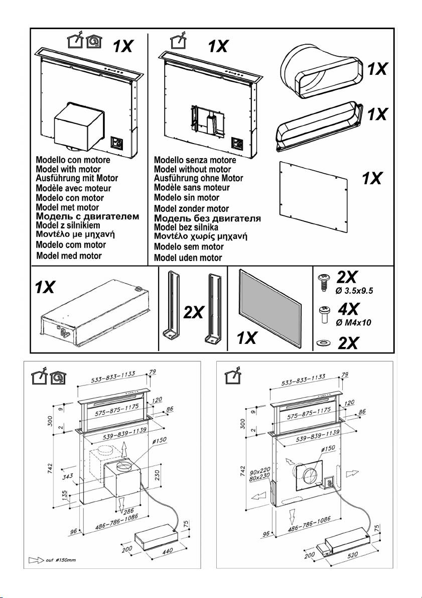
La cappa è realizzata per essere utilizzata in versione
scatola metallica contenente i componenti elettronici almeno a
aspirante ad evacuazione esterna o filtrante a ricircolo interno.
10 cm dal suolo e ad una distanza sufficiente da tutte le fonti
di calore (es: lato di un forno, o piano cottura).
Se le istruzioni di installazione del dispositivo di cottura a gas
specificano una distanza maggiore, bisogna tenerne conto.
Versione aspirante
I vapori vengono evacuati verso l’esterno tramite un tubo di
Collegamento Elettrico
scarico fissato alla flangia di raccordo.
L’allacciamento della cappa alla rete elettrica deve essere
Il diametro del tubo di scarico deve essere equivalente al
effettuato da personale tecnico qualificato e specializzato.
diametro dell'anello di connessione.
La tensione di rete deve corrispondere alla tensione riportata
Attenzione! Il tubo di evacuazione non è fornito e va
sull’etichetta caratteristiche situata all’interno della cappa. Se
acquistato.
provvista di spina allacciare la cappa ad una presa conforme
Nella parte orizzontale, il tubo deve avere una leggera
alle norme vigenti posta in zona accessibile anche dopo
inclinazione verso l’alto (10° circa) in modo da poter
l’installazione. Se sprovvista di spina (collegamento diretto
trasportare l’aria verso l’esterno più facilmente.
alla rete) o la spina non è posta in zona accessibile, anche
Se la cappa è provvista di filtri al carbone, questi devono
dopo installazione, applicare un interruttore bipolare a norma
essere tolti.
che assicuri la disconnessione completa della rete nelle
condizioni della categoria di sovratensione III, conformemente
alle regole di installazione.
Attenzione! Prima di ricollegare il circuito della cappa
Versione filtrante
all’alimentazione di rete e di verificarne il corretto
L’aria aspirata verrà sgrassata e deodorata prima di essere
funzionamento, controllare sempre che il cavo di rete sia stato
riconvogliata nella stanza. Per utilizzare la cappa in questa
montato correttamente.
versione è necessario installare un sistema di filtraggio
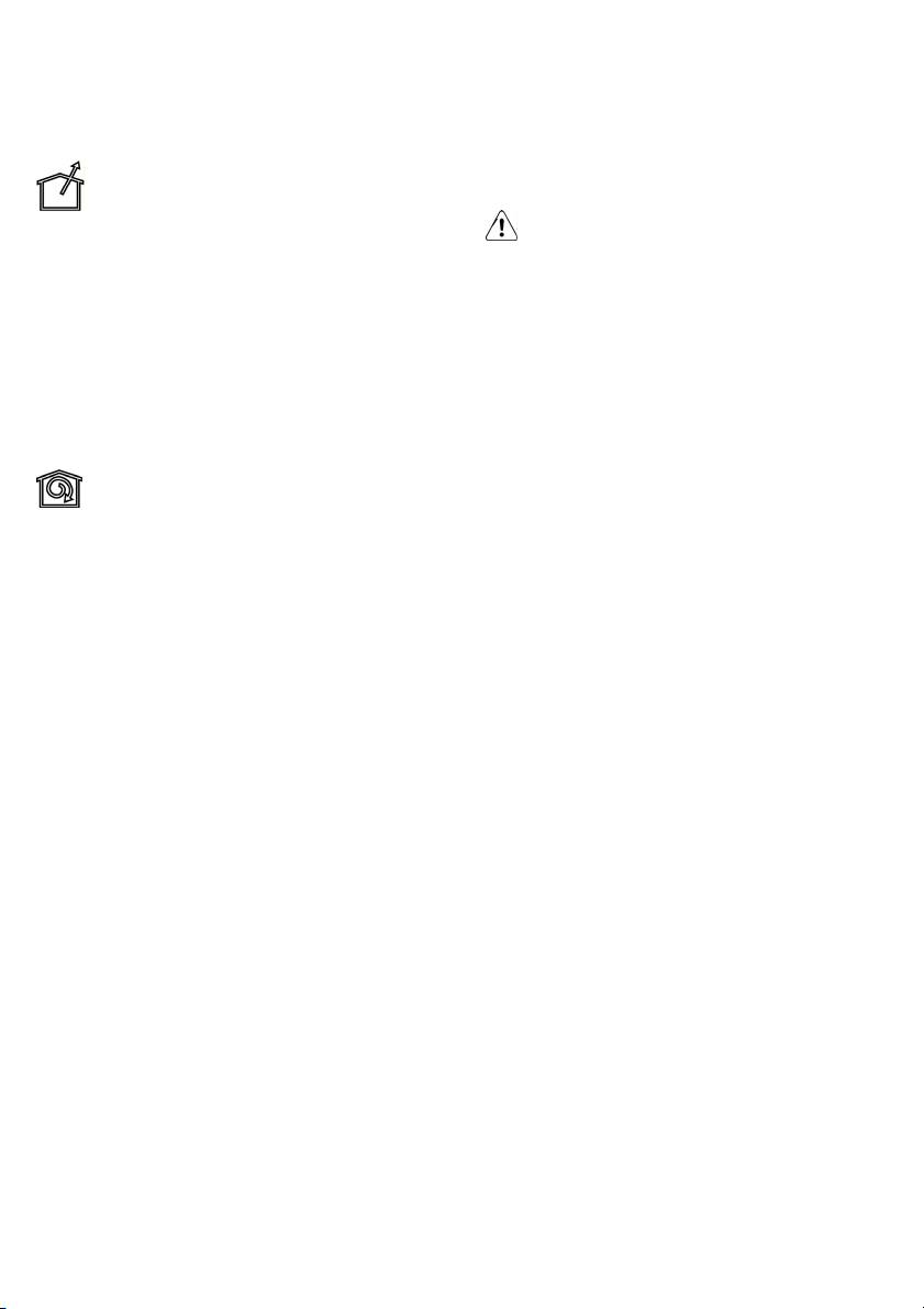
Nota: nelle applicazioni con motore remoto GME collegare il
aggiuntivo a base di carboni attivi.
cavo del gruppo motore nell’apposita morsettiera alloggiata
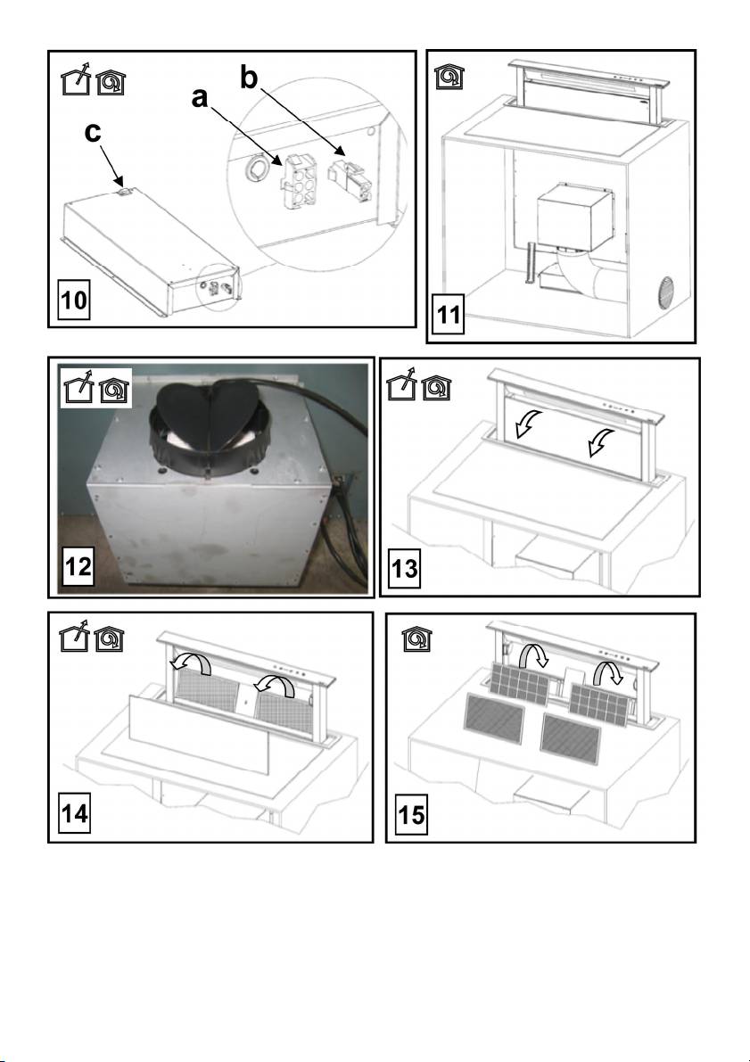
Nota: L’aria riciclata attraverso i filtri carbone viene rinviata
all’interno della scatola in plastica presente nel cablaggio del
nella cucina attraverso un condotto che convoglia l’aria su un
downdraft. Fare attenzione nel rispettare i colori dei cavi
lato del mobile (Fig. 11).
durante il collegamento.
Bloccaggio della valvola di non ritorno
Fig. 21
Attenzione prima di connettere il tubo flessibile di uscita
dell’aria assicurarsi che le valvole di non ritorno del gruppo di
Montaggio
aspirazione siano libere di ruotare liberamente (Fig. 12).
Prima di procedere nell’installazione dell’apparecchio
I modelli senza motore di aspirazione funzionano solo in
verificare che tutti i componenti non siano danneggiati, in caso
versione aspirante e debbono essere collegati ad una unità
contrario contattare il rivenditore e non proseguire con
periferica di aspirazione (non fornita).
l’installazione. Inoltre leggere attentamente tutte le istruzioni
Le istruzioni di collegamento sono fornite con l'unità periferica
di seguito riportate.
di aspirazione.
• Utilizzare un tubo di evacuazione aria che abbia la
Installazione
lunghezza massima non superiore a 5 metri.
Nota: l'installazione deve essere eseguita in modo che sia
• Limitare il numero di curve nella canalizzazione poiché
sempre garantita l'accessibilità della cappa e dei componenti
ogni curva riduce l’efficienza di aspirazione equiparata a
elettronici per eventuali interventi in assistenza
1 metro lineare. (Es: se si utilizzano n°2 curve a 90°, la
tecnica.Nell'installazione del prodotto, si consiglia di
lunghezza della canalizzazione non dovrebbe superare i
mantenere una distanza minima di 400mm trà il piano di
3 metri di lunghezza).
lavoro ed eventuali componenti posti al di sopra della cappa.
• Evitare cambiamenti drastici di direzione.
Questo per rendere priva di ostacoli la corsa verso l'alto
• Utilizzare un condotto con diametro da 150mm costante
(apertura) e verso il basso (chiusura) del pannello di
per tutta la lunghezza.
aspirazione, e per agevolare l'accesso ai comandi della cappa
• Utilizzare un condotto di materiale approvato
posti sul pannello.
normativamente.
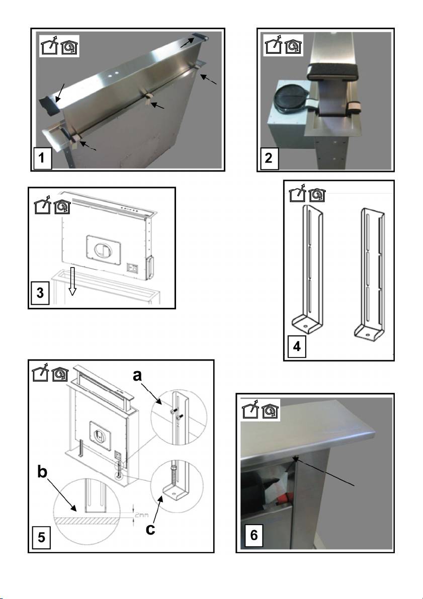
• Rimuovere lo spessore di sicurezza evidenziato nella foto
AVVERTIMENTO: Posizionare la scatola metallica
(Fig. 1-2) al termine dell’installazione.
contenente i componenti elettronici ad una distanza non
• Per il mancato rispetto delle precedenti istruzioni la ditta
inferiore a 65 cm dal piano cottura a gas o comunque a 65 cm
fornitrice non risponderà per problemi di portata o
dal punto di aspirazione della cappa.
rumorosità e nessuna garanzia sarà prestata.
La distanza minima dal bordo del downdraft e il bordo del
• Prima di effettuare il foro controllare che nella parte
piano cottura deve essere almeno di 50mm.
interna del mobile, in corrispondenza della zona di
8
alloggio della cappa, non sia presente la struttura del
Funzionamento
mobile o altri particolari che potrebbero creare problemi
Usare la velocità maggiore in caso di particolare
per la corretta installazione. Verificare che gli ingombri
concentrazione di vapori di cucina. Consigliamo di accendere
della cappa e del piano cottura siano compatibili con il
l'aspirazione 5 minuti prima di iniziare a cucinare e di lasciarla
mobile e quindi sia fattibile l’installazione.
in funzione a cottura terminata per altri 15 minuti circa.
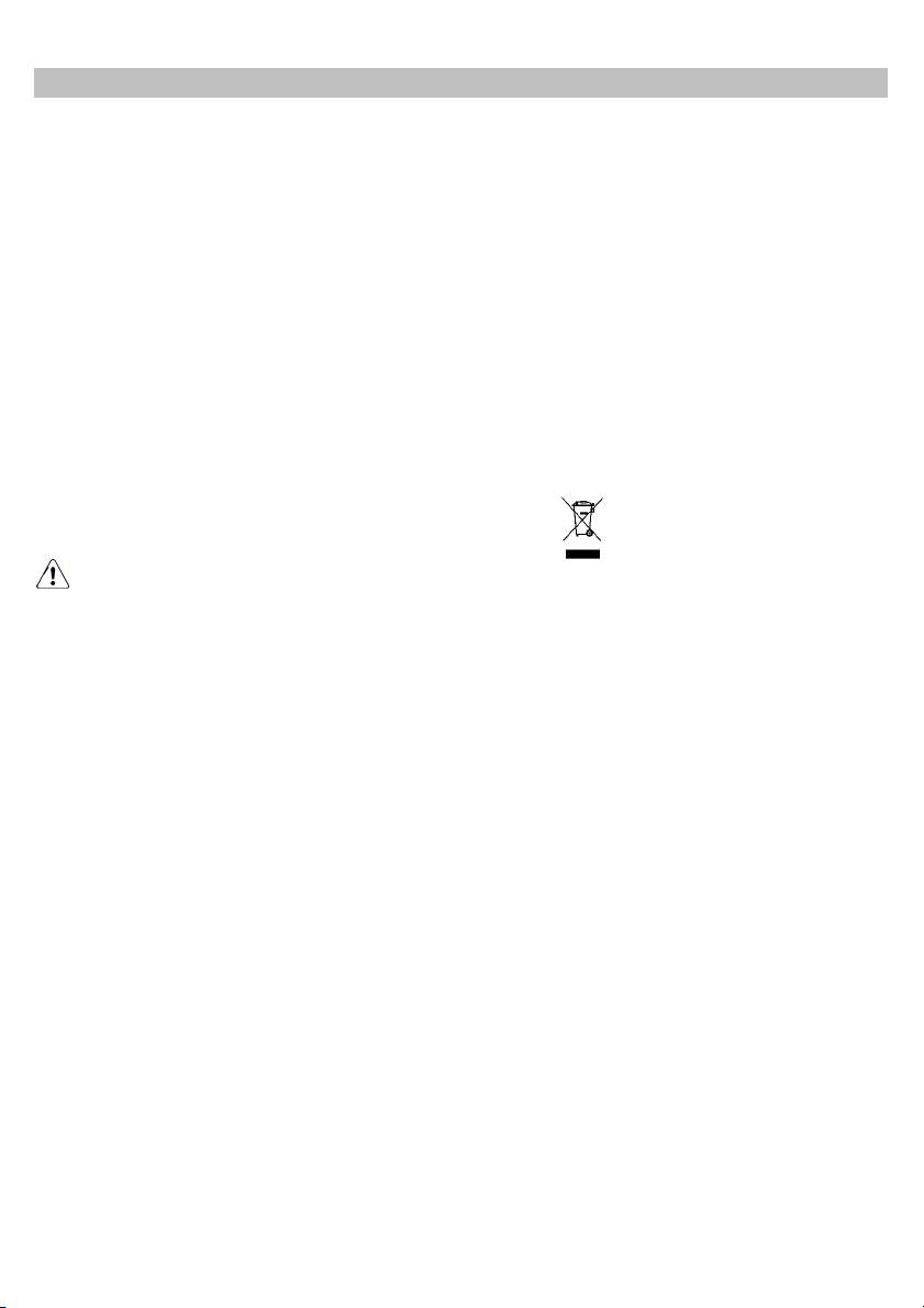
• Effettuare nella parte posteriore del piano cottura, un foro
La cappa è dotata di un dispositivo "TOUCH" per il controllo
rettangolare con le seguenti dimensioni: (Fig.20)
di luci e velocità.
Cappa Modello da 60cm: 542x100mm.
Per il corretto utilizzo leggere attentamente le istruzioni
Cappa Modello da 90cm: 842x100mm.
sottostanti.
Cappa Modello da 120cm: 1142x100mm.
La cappa può essere controllata tramite un telecomando
• Nel caso di versione con motore già montato, togliere le
disponibile come kit accessorio (vedere il paragrafo relativo al
viti e rimuovere il gruppo aspirante per poter inserire la
funzionamento del telecomando).
cappa nel foro praticato.
• Installare la cappa nel foro praticato, inserendolo da
sopra, come indicato (Fig. 3). Nel caso di versione con
motore a bordo occorre rimuovere il gruppo aspirante
prima di procedere all’inserimento del prodotto nel
mobile.
• Fissare la cappa all’interno del mobile utilizzando le
apposite staffe in dotazione (Fig.4). Procedere al
montaggio delle staffe nella parte inferiore della cappa
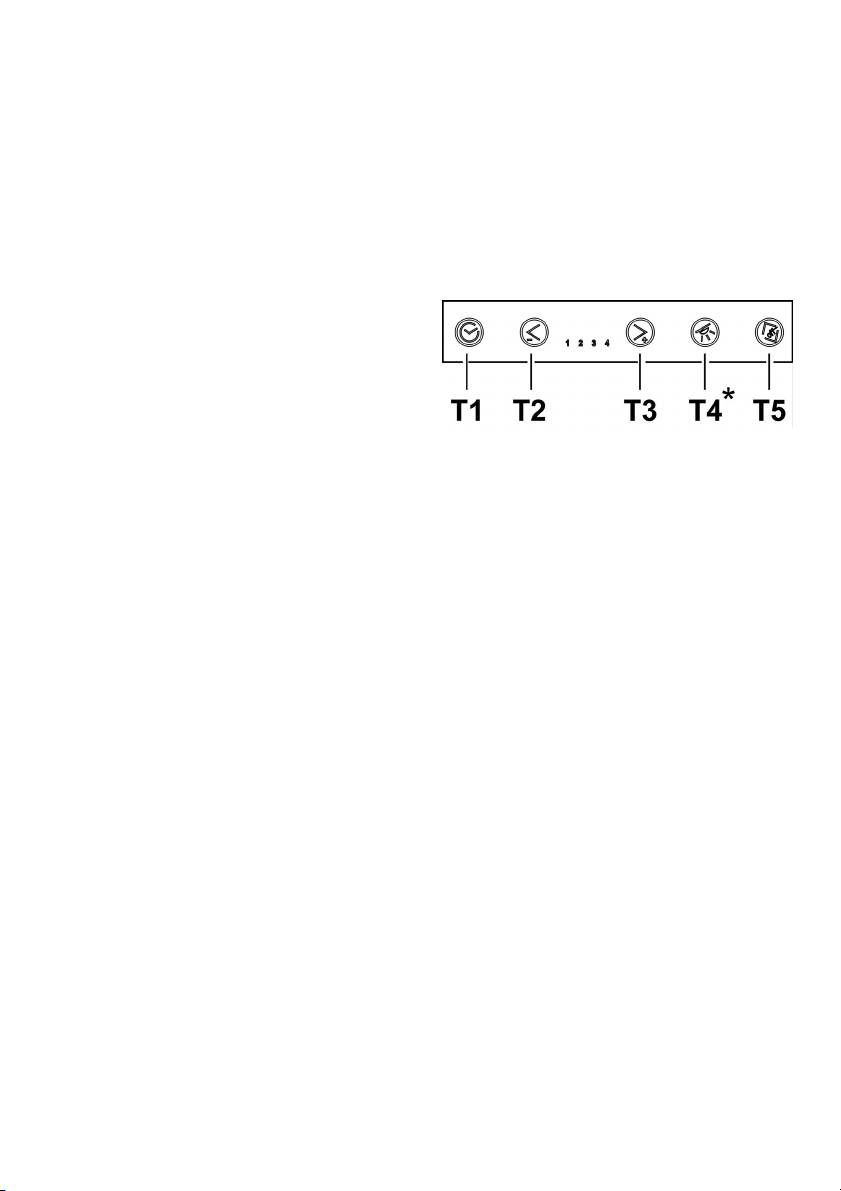
• Tasto T1: ritarda lo spegnimento della cappa
(Fig.5a) facendo in modo che tra la parte inferiore della
temporizzando la velocità impostata di alcuni minuti.
staffa ed il fondo del mobile rimanga una distanza di 2
Tale funzione prevede che, a temporizzazione scaduta,
mm (Fig.5b). Questa distanza permetterà la trazione
la cappa si spenga.
verso il basso del prodotto al momento del fissaggio,
La temporizzazione è così suddivisa:
(Fig.5c), per far aderire perfettamente la cornice inox sul
• velocità (potenza) di aspirazione 1: 20 minuti
piano di lavoro.
• velocità (potenza) di aspirazione 2: 15 minuti
• Prima di inserire le viti nel mobile assicurarsi che il
• velocità (potenza) di aspirazione 3: 10 minuti
prodotto sia perfettamente perpendicolare al piano di
• velocità (potenza) di aspirazione 4: 5 minuti
lavoro.
NB: Azionando il timer la cappa potrebbe passare ad una
• Dopo aver completato l’installazione, e dopo aver
velocità (potenza) di aspirazione minore prima di
collegato il prodotto alla rete elettrica, sollevare la cappa
spegnersi , in quanto su alcune velocità è già prevista
e rimuovere il blocco sportello (Fig. 6).
una temporizzazione sulla riduzione della velocità stessa.
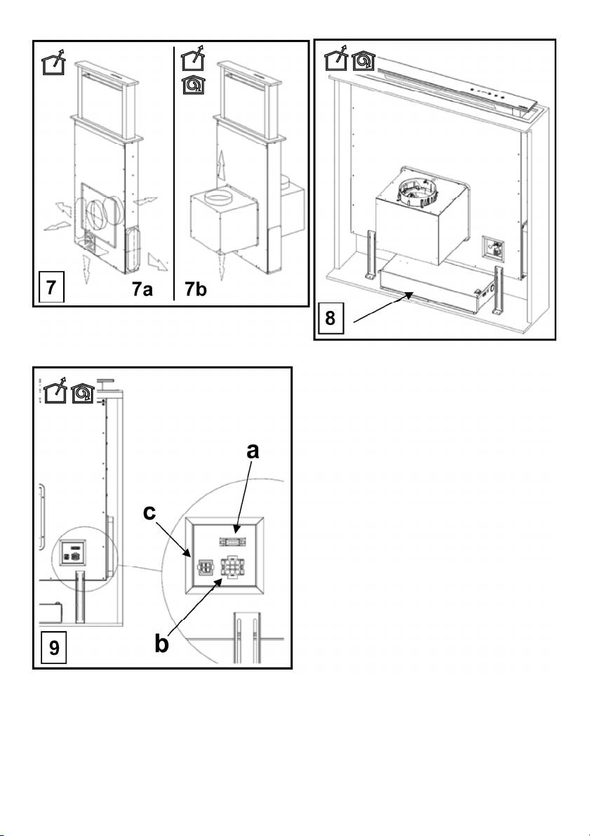
• Nel caso della versione con motore a bordo procedere al
Premendo i tasti T2 e T3 la cappa esce dalla funzione
montaggio del gruppo motore orientando l’uscita dell’aria
temporizzata e la velocità (potenza) di aspirazione
nella posizione prescelta verso il basso o verso l’alto.
aumenta o diminuisce in base al tasto premuto. Durante
(Fig. 7b). Il motore può essere installato sia sul lato
la fase di temporizzazione il led relativo alla velocità
anteriore che sul lato posteriore della cappa. Ad
corrispondente lampeggia.
avvenuta installazione del motore procedere al
• Tasto T2: Decrementa la velocità (potenza) di
montaggio della canalizzazione per l’uscita dell’aria.
aspirazione attiva (4→3→2→1→OFF).
• Nel caso di versione con motore esterno posizionare in
La velocità viene visualizzata tramite l’accensione del led
una zona idonea il gruppo aspirante (motore esterno) e
relativo alla velocità corrispondente.
disporre il condotto di evacuazione dell’aria di scarico.
Il tasto T2 non ha nessun effetto sulla apertura/chiusura
Procedere al montaggio della canalizzazione uscita aria
del pannello di aspirazione.
tra il motore esterno e la cappa. Selezionare l’uscita aria
• Tasto T3: Incrementa la velocità (potenza) di aspirazione
tra le cinque possibilità (Fig. 7a) ed installare il raccordo
attiva (1→2→3→4).
in dotazione.
La velocità viene visualizzata tramite l’accensione del led
• Posizionare la scatola metallica contenente i componenti
relativo alla velocità corrispondente.
elettronici in una zona facilmente accessibile per
Nota: (solo per modelli con motore a bordo o GME 22
eventuali interventi di assistenza (Fig. 8), collegando i
remoto):
connettori elettrici della stessa alla cappa: connettore
la velocità (potenza) di aspirazione 4 è temporizzata per
pulsantiera (Fig. 9a), connettore 9 poli (Fig. 9b),
6 minuti, dopodichè la cappa passerà automaticamente
connettore neon (Fig. 9c)
alla velocità (potenza) di aspirazione 3.
• Nelle applicazioni con motore esterno collegare il cavo
Nota: (solo per GME 88 remoto):
del gruppo motore nell’apposito connettore sulla scatola
dei componenti elettronici (Fig. 10a) se presente
la velocità (potenza) di aspirazione 3 è temporizzata per
collegare anche il connettore bipolare (Fig.10b)
7 minuti, dopodichè la cappa passerà automaticamente
• Collegare il prodotto alla rete elettrica
alla velocità (potenza) di aspirazione 2.
9
la velocità (potenza) di aspirazione 4 è temporizzata per
Premere il tasto “+” o il tasto “-” o il tasto "■" rispettivamente
6 minuti, dopodichè la cappa passerà automaticamente
per aumentare o diminuire o spegnere la velocità (potenza) di
alla velocità (potenza) di aspirazione 2.
aspirazione.
Nota: Se il pannello è chiuso (cappa spenta) il tasto T3
A cappa spenta e pannello di aspirazione chiuso,
aziona prima l'apertura del pannello di aspirazione poi
premendo il tasto "■" o il tasto “+”, la cappa aziona prima
imposta la cappa alla velocità (potenza) di aspirazione 1.
l'apertura del pannello di aspirazione poi imposta la cappa alla
• Tasto T4*: Accende la luce
velocità (potenza) di aspirazione 1.
Nota: Se il pannello di aspirazione è chiuso (cappa
A cappa accesa e pannello di aspirazione aperto premere
spenta) il tasto T4 aziona prima l'apertura del pannello di
il tasto "■" una volta per spegnere la cappa, premere ancora
aspirazione poi accende la luce.
per chiudere il pannello di aspirazione (se accesa si spegne
• Tasto T5: Apre (Alza) e chiude(abbassa) il pannello di
anche la luce).
aspirazione.
A cappa spenta e pannello chiuso, il tasto T5 prima apre
Controllo della luce (A seconda del modello disponibile):
Premere il tasto "◄" o il tasto "►" sino a visualizzare sul
il pannello di aspirazione poi imposta la cappa alla
telecomando il simbolo
velocità (potenza) di aspirazione 1.
La luce centrale può essere accesa e spenta in due modi:
A cappa accesa (a qualunque velocità) e pannello aperto
1. Premere il tasto “+” o il tasto “-” rispettivamente per
il tasto T5 prima spegne la cappa ( e , se accese, spegne
accendere (ON) o spegnere (OFF) la luce centrale.
anche le luci) poi chiude il pannello di aspirazione.
2. Premere il tasto "■" per cambiare lo stato della luce da
spenta (OFF) ad accesa (ON) o viceversa.
* A seconda del modello disponibile.
Nota 1: se il pannello di aspirazione e chiuso, il tasto che
accende la luce, prima apre il pannello.
Nota 2: Con la luce accesa premere il tasto "■" una volta per
Informazioni di funzionamento aggiuntive
spegnere la cappa, se nessuna velocita (potenza)
Durante la rimozione del pannello anteriore per operazioni di
diaspirazione è seleziona premendo ancora ancora il pannello
pulizia e manutenzione, tutte le funzioni elettroniche di
di aspirazione si chiude.
aspirazione e movimento sono bloccate.
Sicurezza antipinzatura: qualora un ostacolo impedisca la
Reset e configurazione della segnalazione di saturazione
chiusura del Downdraft, la chiusura si interrompe e il carrello
dei filtri
risale.
Accendere la cappa ad una qualsiasi velocità (vedi paragrafo
sopra “Selezione delle velocità (potenze) di aspirazione”)
Segnalazione di saturazione del Filtro Grassi.
Premere il tasto "◄" o il tasto "►" sino a visualizzare sul
Ogni 40 ore di utilizzo la cappa segnala la necessità di
eseguire la manutenzione del filtrograssi.
telecomando il simbolo
La segnalazione avviene facendo lampeggiare
contemporaneamente tutti i led di delle velocità (potenze)
diaspirazione.
Premere contemporaneamente per più di 3 secondi i tasti “+”
Reset della segnalazione del filtro grassi
e “-”, tutti i led delle velocità (potenze) di aspirazione smettono
Dopo aver eseguito la manutenzione del filtro grassi, premere
di lampeggiare ad indicare che il reset della segnalazione è
il tasto T1 per più di 3" al fine di resettare la segnalazione.
stato eseguito.
Nota: La segnalazione non è visualizzata a cappa spenta
(OFF), indipendentemente dalla posizione del pannello di
Manutenzione del telecomando
aspirazione.
Pulizia del telecomando:
Uso del telecomando
Pulire il telecomando con un panno morbido ed una soluzione
il telecomando è in grado di controllare tutte le funzionalità
detergente neutra priva di sostanze abrasive
della cappa:
Sostituzione della batteria:
• Aprire il vano della batteria facendo leva con un piccolo
Selezione delle velocità (potenze) di aspirazione
cacciavite a punta piatta.
• Sostiutire la batteria esausta con una nuova da 12 V tipo
Controllo della luce
MN21/23
Nell' inserire la nuova batteria rispettare le polarità
Tasto senza funzioni
indicate nel vano della batteria!
• Richiudere il vano della batteria.
Reset e configurazione della segnalazione di
Smaltimento delle batterie
saturazione dei filtri
Lo smaltimento delle batterie deve essere svolto in accordo
con tutte le normative e leggi nazionali. Non smaltite le
Selezione delle velocità (potenze) di aspirazione:
batterie usate assieme ai rifiuti normali.
Premere il tasto "◄" o il tasto "►" sino a visualizzare sul
Le batterie devono essere smaltite in modo sicuro.
telecomando il simbolo ”
Per maggiori ragguagli circa gli aspetti di protezione
10

dell'ambiente, il riciclaggio e lo smaltimento di batterie,
Filtro antigrasso
contattate gli uffici incaricati della raccolta differenziata.
Trattiene le particelle di grasso derivanti dalla cottura.
Deve essere pulito una volta al mese (o quando il sistema di
Anomalie di funzionamento
indicazione di saturazione dei filtri - se previsto sul modello in
possesso- indica questa necessità), con detergenti non
La cappa non funziona
aggressivi, manualmente oppure in lavastoviglie a basse
Verificate che:
temperature ed a ciclo breve.
• Non vi sia un blackout di corrente
Con il lavaggio in lavastoviglie il filtro antigrasso metallico può
• Sia stata effettivamente selezionata una certa velocità.
scolorirsi ma le sue caratteristiche di filtraggio non cambiano
• Il pannello sia correttamente agganciato.
assolutamente.
• La connessione a 9 poli sia ben inserita (Fig. 9b).
Il montaggio e smontaggio dei filtri antigrasso e dei filtri
• Il tasto rosso di reset posizionato sopra la scatola
carbone va effettuato con il carrello estraibile della cappa in
impianto elettrico sia premuto.
posizione aperta. Per questo,spingere il tasto OFF (T5).
• Nella connessione 9 poli accertarsi che i fili siano ben
Quindi rimuovere il pannello frontale tirando
inseriti nel connettore stesso. (In fase di collegamento la
contemporaneamente sulla parte superiore di ogni lato
troppa pressione esercitata potrebbe piegare i contatti).
(Fig.13).Il pannello ruota in avanti,liberando l ’accesso ai filtri
La cappa ha un rendimento scarso
antigrasso (Fig. 14).
Verificate che:
• La velocità motore selezionata sia sufficiente per la
Filtro ai carboni attivi (Solo per Versione Filtrante)
quantità di fumi e di vapori presenti
Trattiene gli odori sgradevoli derivanti dalla cottura.
• La cucina sia areata sufficientemente da permettere una
La saturazione del filtro carbone si verifica dopo un uso più o
presa d’aria il filtro carbone non sia usurato (cappa in
versione filtrante).
meno prolungato a seconda del tipo di cucina e della
• Il tubo di scarico uscita aria sia privo di ostruzioni.
regolarità della pulizia del filtro grassi. In ogni caso è
• Le valvole di non ritorno del gruppo di aspirazione siano
necessario sostituire la cartuccia al massimo ogni quattro
libere di ruotare.
mesi. NON può essere lavato o rigenerato
Dopo aver tolto i filtri antigrasso, è possibile inserire i filtri
La cappa si arresta nel corso del funzionamento
carbone (Fig. 15) (non in dotazione).
Verificate che:
• Non vi sia un black out di corrente
Sostituzione Lampade
• L’interruttore magnetotermico differenziale (Salvavita)
non sia scattato.
(A seconda del modello disponibile).
Disinserire l’apparecchio dalla rete elettrica.
Attenzione! Prima di toccare le lampade sincerarsi che siano
Manutenzione
fredde.
Attenzione! Prima di qualsiasi operazione di pulizia o
Sostituire la lampada danneggiata con una dello stesso tipo
manutenzione, disinserire la cappa dalla rete elettrica
così come specificato nell'etichetta caratteristica o vicino alla
togliendo la spina o staccando l’interruttore generale
lampada stessa sulla cappa.
dell’abitazione o premendo il tasto rosso nella scatola
comandi (Fig.13c).
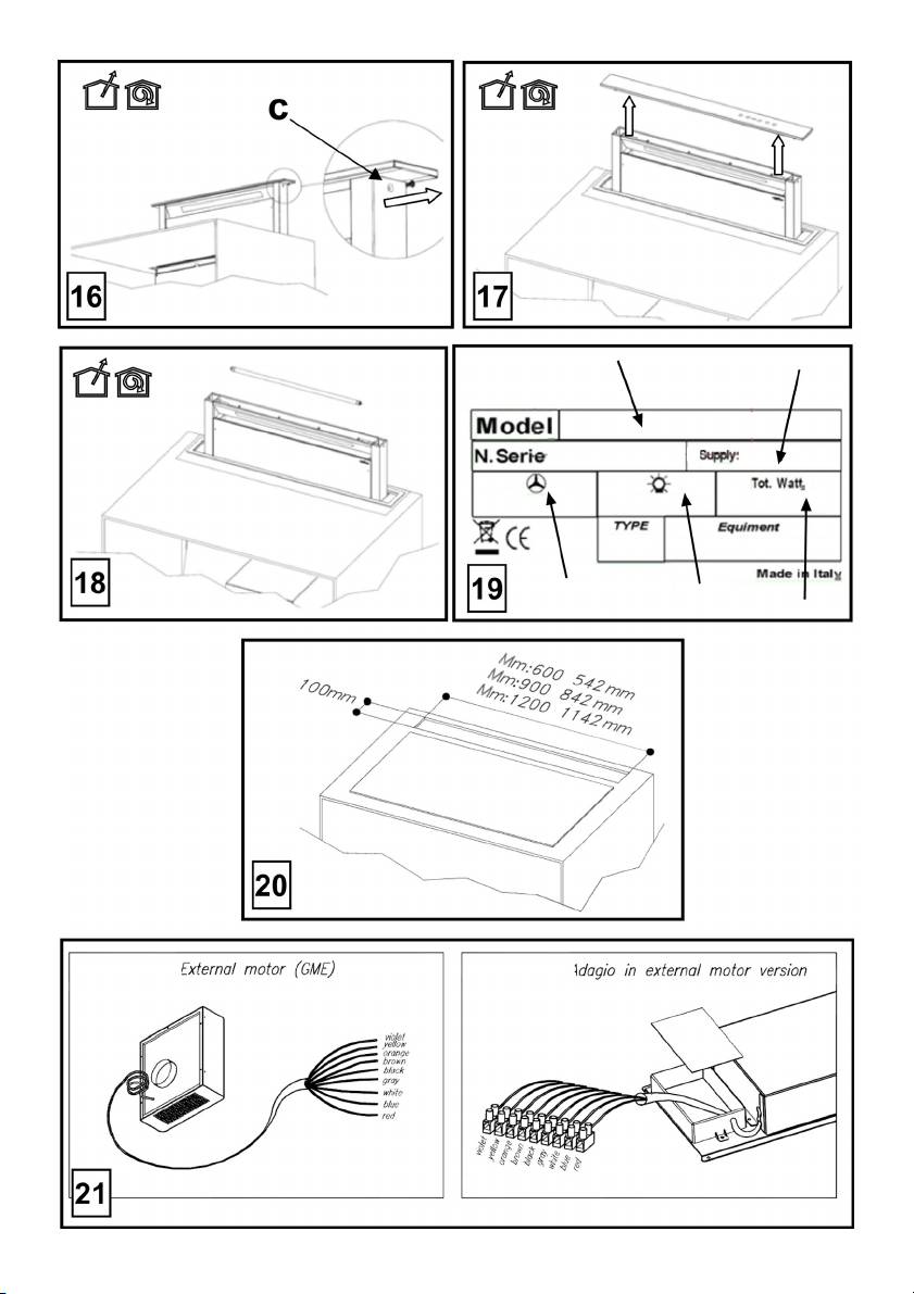
Per la sostituzione del neon procedere come di seguito
Al termine delle operazioni di pulizia o manutenzione
indicato:
della cappa o dei filtri ricollocareil pannello frontale i filtri
1. Sollevare il carrello.
come da istruzioni, verificando la corretta installazione ed
2. Togliere alimentazione. (questa operazione può essere
aggancio, altrimenti la cappa non si accende.
effettuata staccando la spina, se accessibile, o aprire
l’interruttore se previsto in fase di installazione o premere
Pulizia
il tasto rosso nella scatola comandi (Fig. 10c)
La cappa va frequentemente pulita (almeno con la stessa
3. Togliere le viti che fissano il frontale superiore come
frequenza con cui si esegue la manutenzione dei filtri grassi),
indicato in (Fig. 16)
sia internamente che esternamente. Per la pulizia usare un
4. Sollevare il frontale superiore (Fig. 17)
panno inumidito con detersivi liquidi neutri.
5. Togliere il neon danneggiato (Fig. 18) e sostituirlo con
Evitare l’uso di prodotti contenenti abrasivi. NON UTILIZZARE
uno di uguale caratteristiche (Mod.T5 14W 860).
ALCOOL!
Se l'illuminazione non dovesse funzionare, controllate il
Attenzione: L’inosservanza delle norme di pulizia
corretto inserimento delle lampade nella sede prima di
dell’apparecchio e della sostituzione dei filtri comporta rischi di
chiamare l'assistenza tecnica.
incendi. Si raccomanda quindi di attenersi alle istruzioni
suggerite.
Si declina ogni responsabilità per eventuali danni al motore,
incendi provocati da un’impropria manutenzione o
dall’inosservanza delle suddette avvertenze.
11
EN - Instruction on mounting and use
Closely follow the instructions set out in this manual. All
correctly mounted due to the possible risk of electric shocks.
responsibility, for any eventual inconveniences, damages or
We will not accept any responsibility for any faults, damage or
fires caused by not complying with the instructions in this
fires caused to the appliance as a result of the non-
manual, is declined. The hood is conceived for the suction of
observance of the instructions included in this manual. When
cooking fumes and steam and is destined only for domestic
handling the hood do not put hands within the range of action
use.
of the pull-out suction panel (trolley) The hood is equipped
The hood can look different to that illustrated in the
with safety switches which inhibit operation when the front
drawings in this booklet. The instructions for use,
filter panel is unhooked.
maintenance and installation, however, remain the same.
With the intention of constantly improving our products, we
! It is important to conserve this booklet for consultation at
reserve the right to make all the changes in their technical,
any moment. In the case of sale, cession or move, make
functional or design characteristics, deriving from their
sure it is together with the product.
evolution. In case of the version with external motor, the
! Read the instructions carefully: there is important
normal operation of the hood requires the use of a suction unit
information about installation, use and safety.
(external motor) of the same manufacturer. This appliance is
! Do not carry out electrical or mechanical variations on the
marked according to the European directive 2002/96/EC on
product or on the discharge conduits.
Waste Electrical and Electronic Equipment (WEEE). By
! Before proceeding with the installation of the appliance
ensuring this product is disposed of correctly, you will help
verify that there are no damaged all components.
prevent potential negative consequences for the environment
Otherwise contact your dealer and do not proceed with
and human health, which could otherwise be caused by
the installation.
inappropriate waste handling of this product.
Note: the elements marked with the symbol “(*)” are optional
accessories supplied only with some models or elements to
purchase, not supplied.
The symbol
on the product, or on the documents
accompanying the product, indicates that this appliance may
Caution
not be treated as household waste. Instead it should be taken
WARNING! Do not connect the appliance to the mains until
to the appropriate collection point for the recycling of electrical
the installation is fully complete.
Before any cleaning or maintenance operation, disconnect
and electronic equipment..
hood from the mains by removing the plug or disconnecting
Disposal must be carried out in accordance with local
the mains electrical supply. Always wear work gloves for all
environmental regulations for waste disposal.
installation and maintenance operations. The appliance is not
For further detailed information regarding the process,
intended for use by children or persons with impaired physical,
collection and recycling of this product, please contact the
sensorial or mental faculties, or if lacking in experience or
appropriate department of your local authorities or the local
knowledge, unless they are under supervision or have been
department for household waste or the shop where you
trained in the use of the appliance by a person responsible for
purchased this product.
their safety. This appliance is designed to be operated by
adults, children should be monitored to ensure that they do
Appliance designed, tested and manufactured according to:
not play with the appliance. This appliance is designed to be
• Safety: EN/IEC 60335-1; EN/IEC 60335-2-31, EN/IEC
operated by adults. Children should not be allowed to tamper
62233.
with the controls or play with the appliance. Never use the
• Performance: EN/IEC 61591; ISO 5167-1; ISO 5167-3; ISO
hood without effectively mounted grating! The hood must
5168; EN/IEC 60704-1; EN/IEC 60704-2-13; ISO 3741; EN
NEVER be used as a support surface unless specifically
50564; IEC 62301.
indicated. The premises where the appliance is installed must
• EMC: EN 55014-1; CISPR 14-1; EN 55014-2; CISPR 14-2;
be sufficiently ventilated, when the kitchen hood is used
EN/IEC 61000-3-2; EN/IEC 61000-3-3. Suggestions for a
together with other gas combustion devices or other fuels.
correct use in order to reduce the environmental impact:
The ducting system for this appliance must not be connected
Switch ON the hood at minimum speed when you start
to any existing ventilation system which is being used for any
cooking and kept it running for few minutes after cooking is
other purpose such as discharging exhaust fumes from
finished. Increase the speed only in case of large amount of
appliances burning gas or other fuels. The flaming of foods
smoke and vapour and use boost speed(s) only in extreme
beneath the hood itself is severely prohibited. The use of
situations. Replace the charcoal filter(s) when necessary to
exposed flames is detrimental to the filters and may cause a
maintain a good odour reduction efficiency. Clean the grease
fire risk, and must therefore be avoided in all circumstances.
filter(s) when necessary to maintain a good grease filter
Any frying must be done with care in order to make sure that
efficiency. Use the maximum diameter of the ducting system
the oil does not overheat and ignite. Accessible parts of the
indicated in this manual to optimize efficiency and minimize
hood may became hot when used with cooking appliance.
noise.
With regards to the technical and safety measures to be
Additional Installation Specifications:
adopted for fume discharging it is important to closely follow
Use only the fixing screws supplied with the product for
the regulations provided by the local authorities. The hood
installation or, if not supplied, purchase the correct screws
must be regularly cleaned on both the inside and outside (AT
type. Use the correct length for the screws which are identified
LEAST ONCE A MONTH). This must be completed in
in the Installation Guide. In case of doubt, consult an
accordance with the maintenance instructions provided in this
authorised service assistance centre or similar qualified
manual). Failure to follow the instructions provided in this user
guide regarding the cleaning of the hood and filters will lead to
person.
the risk of fires. Do not use or leave the hood without the lamp
12
WARNING! Failure to install the screws or fixing device in
WARNING: Put the metal box containing the electronic
accordance with these instructions may result in electrical
components at a distance not shorter than 65 cm from the gas
hazards.
hob or 65 cm from the hood suction point.
The minimum distance between downdraft edge and hob
Use
edge must be at least 50mm.
The hood is designed to be used either for exhausting or filter
version.
RECOMMENDATION: We recommend you to install the
metal box containing the electronic components at a distance
of at least 10 cm from the ground and sufficiently from all the
sources of heat (e.g.: side of an oven or hob).
If the instructions for installation for the gas hob specify a
Ducting version
greater distance, this must be adhered to.
In this case the fumes are conveyed outside of the building by
means of a special pipe connected with the connection ring
Electrical connection
located on top of the hood.
The hood must be connected to the mains supply by qualified
Attention! The exhausting pipe is not supplied and must be
and trained technicians.
purchased apart.
The mains power supply must correspond to the rating
Diameter of the exhausting pipe must be equal to that of the
indicated on the plate situated inside the hood. If provided with
connection ring.
a plug connect the hood to a socket in compliance with current
In the horizontal runs the exhausting pipe must be slightly
regulations and positioned in an accessible area, after
slanted (about 10°) and directed upwards to vent the air easily
installation. If it not fitted with a plug (direct mains connection)
from the room to the outside.
or if the plug is not located in an accessible area, after
Attention! If the hood is supplied with active charcoal filter,
installation, apply a double pole switch in accordance with
then it must be removed.
standards which assures the complete disconnection of the
mains under conditions relating to over-current category III, in
accordance with installation instructions.
Filter version
Warning! Before re-connecting the hood circuit to the mains
One active charcoal filter is needed for this and can be
supply and checking the efficient function, always check that
obtained from your usual retailer.
the mains cable is correctly assembled.
The filter removes the grease and smells from the extracted
Note: in applications with a remote GME motor, connect the
air before sending it back into the room through the upper
cable of the motor unit in the designated terminal board
outlet grid.
located inside the plastic box in the downdraft's wiring. Make
Note: The recycled air in the charcoal filter is sent back to the
sure you follow the colours of the cables during the
kitchen through a duct which conveys air on a side of the
connection.
cabinet (Picture 11).
Fig. 20
Non-return valve locking
Mounting
Attention, before connecting the flexible air outlet pipe make
Before starting to mount the appliance, make sure that no
sure that the non-return valves of the suction unit can freely
component is damaged, otherwise contact the dealer and stop
rotate (Picture 12).
mounting. In addition, read all the instructions below carefully.
The models with no suction motor only operate in ducting
• Use an air outlet pipe no longer than 5 metres.
mode, and must be connected to an external suction device
• Limit the number of curves in the duct since each curve
(not supplied).
reduces the suction effectiveness equivalent to 1 linear
The connecting instructions are supplied with the peripheral
metre. (E.g.: if two 90° curves are used, the duct should
suction unit.
be no longer than 3 metres).
• Avoid drastic changes of direction.
Installation
• Use a duct with 150mm diameter constant for the whole
Note: The installation must be performed so that accessibility
length.
to the hood and its electronic components is always ensured
• Use a duct made of standard complying material.
for possible technical assistance interventions.
• Remove the safety shim highlighted in the picture (Fig. 1-
When installing the product, it is recommended to keep a
2) at the end of the installation.
minimum distance of 400mm between the worktop and any
• In case of failure to observe the instructions above, the
components laid on top of the hood.
supplier can not be held responsible for capacity or noise
This is to let the suction panel move upwards (opening) and
problems and no warranty will be granted.
downwards (closing) without any obstacles, and to facilitate
• Before making the hole, make sure that the inside of the
access to the hood controls on the panel.
cabinet, near the hood housing area, does not have the
structure of the cabinet or other particulars which may
cause problems for the proper installation. Make sure
13

that the overall dimensions of the hood and the hob ae
compatible with the cabinet and therefore the installation
Operation
is feasible.
Use the high suction speed in cases of concentrated kitchen
• Perform, in the back of the hob, a rectangular hole with
vapours. It is recommended that the cooker hood suction is
the following dimensions:
switched on for 5 minutes prior to cooking and to leave in
Hood 60cm Model: 542x100mm.
operation during cooking and for another 15 minutes
Hood 90cm Model: 842x100mm.
approximately after terminating cooking.
Hood 120cm Model: 1142x100mm
The hood is equipped with a “TOUCH” device to control the
• In case of version with motor already mounted, remove
lights and speed.
the screws and the suction unit to insert the hood into the
For the correct use please carefully read the intructions below.
hole made.
The cooker hood can be controlled through a remote control
• Install the hood in the hole made, inserting it from above,
available as accessory kit (see the paragraph relating to the
as shown (Fig. 3). In case of version with motor on
functioning of the remote control).
board, it is necessary to remove the suction unit before
inserting the product into the cabinet.
• Fix the hood inside the cainet using the special brackets
supplied (Fig. 4). Start mounting the brackets in the lower
part of the hood (Fig. 5a) making sure that there is a
distance of 2 mm between the lower part of the bracket
and the cabinet bottom (Fig. 5b). This distance allows
the traction of the product downwards on fixing, (Fig. 5c),
so that the stainless steel frame adheres perfectly on the
• Key T1: delays hood switching off timing the speed set
worktop.
for some minutes.
• Before inserting the screws into the cabinet, make sure
By such function, when the timing is elapsed, the hood
that the product is perfectly perpendicular to the worktop.
switches off.
• After completing the installation and connecting the
The timing is divided as follows:
product to the power supply, lift the hood and remove the
• suction speed (power) 1: 20 minutes
door lock (Fig. 6).
• suction speed (power) 2: 15 minutes
• In case of version with motor on board start mounting the
• suction speed (power) 3: 10 minutes
motor unit directing the air outlet to the chosen position
• suction speed (power) 4: 5 minutes
downwards or upwards (Fig. 7b). The motor can be
PLEASE NOTE: When operating the timer, the hood
installed on both the front side and the back one of the
might switch to a lower intake speed (power) before
hood. Once the installationof the motor has been
turning off, as on some speeds there is already a
comleted, start mounting the duct for the air outlet.
timing on the speed reduction itself.
• In case of version with external motor put the suction unit
When keys T2 and T3 are pressed, the hood leaves the
(external motor) in a suitable area and arrange the air
timed function and the suction speed (power) increases
outlet duct. Start mounting the air outlet duct between the
or decreases according to the key pressed. During the
external motor and the hood. Select the air outlet among
timing phase the LED related to the corresponding speed
the five possibilities (Fig. 7a) and install the union
flashes.
supplied.
• Key T2: Decreases the active suction speed (power)
• Put the metal box containing the electronic components
(4→3→2→1→OFF).
in an easily accessible area for any assistance
The speed is displayed through the LED related to the
operations (Fig. 8), connecting the electric connectors of
corresponding speed.
the same to the hood: pushbutton panel connector (Fig.
Key T2 has no effect on the opening/closure of the
9a), 9-pole connector (Fig. 9b), neon connector (Fig. 9c)
suction panel.
• In case of installation with remote motor,connect the
• Key T3: Increases the active suction speed (power)
power unit cable to the special connector placed on the
(1→2→3→4).
electronic components box (Fig.10a),and also connect
The speed is displayed through the LED related to the
the 2-pole connector,if supplied (Fig.10b)
corresponding speed.
• Connect the product to the power supply
Note: (only for models fitted with a motor or a remote
GME 22):
Suction speed 4 (power) is timed for 6 minutes, after
which the hood will automatically switch to suction speed
3 (power).
14
Note: (only for remote GME 88):
on the remote control: ”
Suction speed 3 (power) is timed for 7 minutes, after
Press key “+” or “-” or "■" respectively to increase or reduce
which the hood will automatically switch to suction speed
or switch off the suction speed (power).
2 (power).
When the hood is off and the suction panel closed, by
Suction speed 4 (power) is timed for 6 minutes, after
pressing key "■" or “+”, the hood activates the opening of the
which the hood will automatically switch to suction speed
suction panel first and then sets the hood to the suction speed
2 (power).
(power) 1.
Note: If the panel is closed (hood is off) key T3 activates
When the hood is on and the suction panel open press key
the opening of the suction panel first and then sets the
"■" once to switch off the hood, press again to close the
hood to the suction speed (power) 1.
suction panel (if it is on, the light is switched off as well).
• Key T4*: Switches on the light
Note: If the suction panel is closed (hood is off) key T4
Light control (Depending on the model available):
activates the opening of the suction panel first and then
Press key "◄" or "►" until the remote control displays the
switches on the light.
symbol
The central light can be switched on and off in two ways:
• Key T5: Opens (Lifts) and closes (lowers) the suction
1. Press key “+” or “-” respectively to switch on (ON) or off
panel.
(OFF) the central light.
With the hood switched off and the panel closed, key T5
2. Press key "■" to change the light state from off (OFF) to
opens the suction panel first and then sets the hood to
on (ON) or viceversa.
the suction speed (power) 1.
Note 1: if the suction panel is closed, the key switching on the
With the hood switched on (at any speed) and the panel
light opens the panel first.
open, key T5 switches off the hood first (and, if they are
Note 2: With the light switched on, press key "■" once to
switch off the hood, if no suction speed (power) is selected,
on, it switches off the lights as well) and then closes the
the suction panel is closed by pressing again.
suction panel.
Reset and configuration of the filter saturation signal
* Depending on the model available.
Switch on the hood at any speed (see paragraph above
“Selection of the suction speeds (powers)”)
Additional operating information
Press key "◄" or "►" until the remote control displays the
During the removal of the front panel due to cleaning and
maintenance operations, all the electronic functions of suction
symbol
and movement are locked.
Anti-pinch safety: if an obstacle obstructs the closure of the
Press keys “+” and “-“ contemporaneously for more than 3
Downdraft, the closure is stopped and the trolley goes up.
seconds, all the suction speed LEDs (powers) stop flashing,
showing that the reset of the signal has been carried out.
Grease Filter saturation signal.
Every 40 hours of use the hood signals the need for
Maintenance of the remote control
maintenance of the grease filter.
The signal is by making all the suction speed LEDs (powers)
Cleaning the remote control:
flash contemporaneously.
Clean the remote control with a damp cloth and a neutral
Reset of the grease filter signal
solution of detergent without abrasive substances.
After carrying out the maintenance of the grease filter, press
key T1 for more than 3" in order to reset the signal.
Changing the battery:
Note: The signal is not displayed with hood switched off
• Open the battery casing using a small screwdriver with a
(OFF), regardless of the position of the suction panel.
flat point.
• Change the finished battery with a new one of 12 V type
Use of the remote control
MN21/23
the remote control can control all the functions of the hood:
In inserting the new battery respect the polarity indicated
on the battery casing!
• Close the battery casing up again.
Selection of the suction speeds (powers)
Disposal of the batteries
Ultimate disposal of the batteries should be handled according
Control of the light
to all national laws and regulations. Do not place used
Key without functions
batteries in your regular waste.
Ultimate disposal of the batteries must be done safely.
Reset and configuration of the filter saturation signal
Contact your local waste management officials for other
information regarding the environmentally sound collection,
Selection of the suction speeds (powers):
recycling, and disposal of the batteries.
Press key "◄" or "►" until the following symbol is displayed
15

Operation anomalies
Grease filter
Traps cooking grease particles.
The hood does not work
This must be cleaned once a month (or when the filter
Make sure that:
saturation indication system – if envisaged on the model in
• There is no current blackout
possession – indicates this necessity) using non aggressive
• A speed has been effectively selected.
detergents, either by hand or in the dishwasher, which must
• The panel is correctly hooked.
be set to a low temperature and a short cycle.
• The 9-pole connection is well inserted (Picture 9b).
When washed in a dishwasher, the grease filter may discolour
• The red reset key above the electric system box is
slightly, but this does not affect its filtering capacity.
pressed.
When inserting and removing grease filters and charcoal
• The wires in the 9-pole connection are well inserted into
filters, please make sure that the extractable unit of the hood
the connector. (During connection, exerting an
is in open position .In order to do this,pull the OFF (T5)key.
overpressure may cause the contacts to bend).
Then remove the front panel ,by pulling on the upper part of
each side at the same time (Fig.13).
The hood has low efficiency
The panel turns forward ,so that grease filters can be inserted
Make sure that:
(Fig.14).
• The motor speed selected is sufficient for the quantity of
fumes present
Charcoal filter (filter version only)
• The kitchen is aired enough to allow an air intake and the
It absorbs unpleasant odours caused by cooking.
charcoal filter is not worn out (filter version hood).
The saturation of the charcoal filter occurs after more or less
• The air outlet pipe is not clogged.
prolonged use, depending on the type of cooking and the
• The suction unit non-return valves can rotate freely.
regularity of cleaning of the grease filter.
In any case it is necessary to replace the cartridge at least
The hood stops during operation
every four mounths.
Make sure that:
The charcoal filter may NOT be washed or regenerated.
• There is no current blackout
After removing the grease filter, it is possible to insert the
• The differential magnetothermal switch (automatic circuit
charcoal filters (Fig. 15) (not supplied).
breaker) has not been released.
Replacing lamps
Maintenance
(Depending on the model available).Disconnect the appliance
Attention! Before any cleaning or maintenance operation,
from the electricity.
disconnect the hood from the power supply removing the
Warning! Prior to touching the light bulbs ensure they are
plug or switching off the master switch of the house or
cooled down.
pressing the red button in the control box (Fig. 13c).
Replace the old light bulb with the one of the same type as
At the end of the clearing or maintenance operations on
specified in the feature label or near the light lamp on the
the hood or the filters, put the front panel and the filters
hood.
back to their place following the instructions, checking
the correct installation and hooking, otherwise the hood
To replace the neon proceed as follows:
will not switch on.
1. Lift the trolley.
2. Disconnect from power supply. (this operation can be
Cleaning
carried out by disconnecting the plug, if accessible, or
The cooker hood should be cleaned regularly (at least with the
open the switch if envisaged during installation or press
same frequency with which you carry out maintenance of the
the red button in the control box (Fig. 10c)
fat filters) internally and externally. Clean using the cloth
3. Remove the screws which fix the upper front as shown in
dampened with neutral liquid detergent. Do not use abrasive
(Fig. 16)
products. DO NOT USE ALCOHOL!
4. Lift the upper front (Fig. 17)
WARNING: Failure to carry out the basic cleaning
5. Remove the damaged neon (Fig. 18) and replace it with
recommendations of the cooker hood and replacement of the
one having the same characteristics (Mod.T5 14W 860).
filters may cause fire risks.
Therefore, we recommend observing these instructions.
If the lights do not work, make sure that the lamps are fitted
The manufacturer declines all responsibility for any damage to
properly into their housings before you call for technical
the motor or any fire damage linked to inappropriate
assistance.
maintenance or failure to observe the above safety
recommendations.
16
DE - Montage- und Gebrauchsanweisung
Die Anweisungen, die in diesem Handbuch gegeben
Gebrauch mit Kochgeräten heiß werden. In Bezug auf
werden, müssen strikt eingehalten werden. Es wird
technische Maßnahmen und Sicherheitsmaßnahmen für die
keinerlei Haftung übernommen für mögliche Mängel, Schäden
Ableitung der Abluft sind die Vorschriften der zuständigen
oder Brände der Dunstabzugshaube, die auf die
örtlichen Behörden strengstens einzuhalten. Die Haube muss
Nichtbeachtung der Vorschriften in diesem Handbuch
regelmäßig innen und außen gereinigt werden (MINDESTENS
zurückzuführen sind. Die Dunstabzugshaube wurde für die
EINMAL IM MONAT, diesbezüglich sind in jedem Fall die
Absaugung der beim Kochen entstehenden Dünste und
ausdrücklichen Angaben in der Wartungsanleitung dieses
Dämpfe entwickelt. Sie ist nur für den Hausgebrauch
Handbuchs zu beachten). Eine Nichtbeachtung der
geeignet.
Vorschriften zur Reinigung der Haube sowie zum
Die Dunstabzugshaube kann anders aussehen als auf den
Auswechseln und Reinigen der Filter führt zu Brandgefahr.
Abbildungen in der vorliegenden Bedienungsanleitung.
Um das Risiko eines Stromschlages zu vermeiden, darf die
Die Bedienungsanleitungen, die Wartung und die
Dunstabzugshaube ohne richtig eingesetzte Lampen nicht
Installation sind aber gleich.
betrieben werden. Es wird keinerlei Haftung übernommen für
! Die Bedienungsanleitung muss aufbewahrt werden,
Fehler, Schäden oder Brände des Gerätes, die durch
damit jederzeit ein Nachschlagen möglich ist. Bei
Nichteinhaltung der in diesem Handbuch aufgeführten
Verkauf, Abtretung oder Umzug muss die
Anweisungen verschuldet wurden. Beim Handhaben der
Bedienungsanleitung immer beim Produkt bleiben.
Abzugshaube achten Sie darauf, dass Ihre Hände nicht in
! Die Bedienungsanleitung muss aufmerksam gelesen
Reichweite des herausziehbaren Paneels (Abzug) gelangen.
werden, da sie wichtige Informationen über Installation,
Die Haube ist mit Sicherheitsschaltern versehen, die den
Gebrauch und Sicherheit enthält.
Betrieb der Haube abschaltet, wenn das vordere Filterpaneel
! Es dürfen keine elektrischen oder mechanischen
ausgehakt wird.
Änderungen am Gerät oder an den Abluftleitungen
vorgenommen werden.
In der Absicht unsere Produkte ständig zu verbessern,
! Vergewissern Sie sich vor der Installation, dass das
behalten wir uns das Recht vor, an den technischen,
Gerät keine Transportschäden aufweist. Bei auftretenden
funktionellen und ästhetischen Eigenschaften alle
Problemen setzen Sie sich bitte mit Ihrem Händler in
Veränderungen vorzunehmen, die sich aus ihrer
Verbindung.
Hinweis: Die mit dem (*) gekennzeichneten Teile sind
Weiterentwicklung ergeben. Bei der Version mit externem
Zubehörteile, die nur bei einigen Modellen im Lieferumfang
Motor muss nur ein Abluftmotor (externer Motor) verwendet
enthalten sind oder Teile, die nicht im Lieferumfang enthalten
werden, der vom gleichen Hersteller stammt wie das Gerät.
sind, und somit extra erworben werden müssen.
In Übereinstimmung mit den Anforderungen der Europäischen
Richtlinie 2002/96/EG über Elektro- und Elektronik-Altgeräte
Warnung
(WEEE) ist vorliegendes Gerät mit einer Kennzeichnung
Achtung! Das Gerät nicht an das Stromnetz anschließen,
versehen.
solange die Installation noch nicht abgeschlossen ist.
Sie leisten einen positiven Beitrag für den Schutz der Umwelt
Vor Beginn sämtlicher Reinigungs- oder Wartungsarbeiten
und die Gesundheit des Menschen, wenn Sie dieses Gerät
muss das Gerät durch Ziehen des Steckers oder Betätigen
einer gesonderten Abfallsammlung zuführen. Im unsortierten
des Hauptschalters der Wohnung vom Stromnetz getrennt
werden. Bei allen Installations- und Instandhaltungsarbeiten
Siedlungsmüll könnte ein solches Gerät durch unsachgemäße
immer Schutzhandschuhe tragen. Kinder nicht mit dem Gerät
Entsorgung negative Konsequenzen nach sich ziehen.
spielen lassen. Erwachsene und Kinder dürfen nie
Auf dem Produkt oder der beiliegenden
unbeaufsichtigt das Gerät benutzen,
– wenn sie körperlich oder geistig dazu nicht in der Lage sind,
– oder wenn ihnen Wissen und Erfahrung fehlen, das Gerät
richtig und sicher zu bedienen.
Produktdokumentation ist folgendes Symbol
einer
Die Dunstabzugshaube niemals ohne korrekt montiertes Gitter
durchgestrichenen Abfalltonne abgebildet. Es weist darauf
in Betrieb setzen!
hin, dass eine Entsorgung im normalen Haushaltsabfall nicht
Die Dunstabzugshaube darf NIEMALS als Abstellfläche
zulässig ist. Entsorgen Sie dieses Produkt im Recyclinghof mit
verwendet werden, sofern dies nicht ausdrücklich angegeben
einer getrennten Sammlung für Elektro- und Elektronikgeräte.
wird. Der Raum muss über eine hinreichende Belüftung
Die Entsorgung muss gemäß den örtlichen Bestimmungen zur
verfügen, wenn die Dunstabzugshaube mit anderen gas- oder
Abfallbeseitigung erfolgen.
brennstoffbetriebenen Geräten gleichzeitig verwendet wird.
Bei gleichzeitigem Betrieb der Dunstabzugshaube im
Bitte wenden Sie sich an die zuständigen Behörden Ihrer
Abluftbetrieb und gas- oder brennstoffbetriebenen Geräten
Gemeindeverwaltung, an den lokalen Recyclinghof für
darf im Aufstellraum gas- oder brennstoffbetriebenen Geräten
Haushaltsmüll oder an den Händler, bei dem Sie dieses Gerät
-5
der Unterdruck nicht größer als 4 Pa (4 x 10
bar) sein. Die
erworben haben, um weitere Informationen über Behandlung,
angesaugte Luft darf nicht in Rohre geleitet werden, die für die
Verwertung und Wiederverwendung dieses Produkts zu
Ableitung der Abgase von gas- oder brennstoffbetriebenen
erhalten.
Geräten genutzt werden. Es ist strengstens verboten, unter
der Haube mit offener Flamme zu kochen. Eine offene
Flamme beschädigt die Filter und kann Brände verursachen
Gerät entwickelt, getestet und hergestellt nach:
und muss deshalb strikt vermieden werden. Das Frittieren
•Safety: EN/IEC 60335-1; EN/IEC 60335-2-31, EN/IEC 62233.
muss unter Aufsicht erfolgen, um zu vermeiden, dass das
•Performance: EN/IEC 61591; ISO 5167-1; ISO 5167-3; ISO
überhitzte Öl Feuer fängt. Zugängliche Teile können beim
5168; EN/IEC 60704-1; EN/IEC 60704-2-13; ISO 3741; EN
17
50564; IEC 62301.
Befestigung
•EMC: EN 55014-1; CISPR 14-1; EN 55014-2; CISPR 14-2;
Wichtig: Die Haube muss so installiert werden, dass sie zur
EN/IEC 61000-3-2; EN/IEC 61000-3-3. Empfehlungen für eine
korrekte Verwendung, um die Umweltbelastung zu verringern:
Wartung zugänglich bleibt.
Schalten Sie Haube beim Kochbeginn bei kleinster
Bei der Befestigung der Abzugshaube sollte der Abstand
Geschwindigkeit EIN und lassen Sie die Haube einige
zwischen der Kochfläche und den Elementen, die sich oben
Minuten nachlaufen, wenn Sie mit dem Kochen fertig sind.
an der Dunstabzugshaube befinden könnten, 400 mm nicht
Erhöhen Sie die Geschwindigkeit nur bei großen Mengen von
unterschreiten, um den Hub nach oben (Öffnen) und nach
Kochdunst und Dampf und benutzen Sie die Intesivstufe(n)
unten (Schliessen) des Abzugspaneels nicht zu hemmen und
nur bei extemen Situationen. Wechseln Sie die Kohlefilter,
den Zugang zu den Bedienelementen an dem Bedienfeld zu
wenn notwendig, um eine gute Geruchsreduzierung zu
gewährleisten. Säubern Sie die Fettfilter, wenn notwendig,
vereinfachen.
um eine gute Fettfilterungseffizienz zu gewährleisten.
Verwenden Sie den in der Gebrauchsanweisung
HINWEIS: das Metallgehäuse mit den elektronischen
angegebenen grössten Durchmesser des
Bauteilen muss mindestens 65 cm von dem Gasherd oder von
Luftaustrittssystems, um die Leistungsfähigkeit zu optimieren
der Saugöffnung der Haube installiert werden.
und die Geräuschentwicklung zu minimieren.
Der Mindestabstand zwischen der Haube und dem Rand des
WARNUNG! Erfolgt die Installation der Schrauben oder
Kochfeldes muss wenigstens 50 mm sein.
Befestigungsvorrichtungen nicht entsprechend den
vorliegenden Anweisungen, führt dies zu Gefahr durch
Stromschlag.
VORSICHT: das Metallgehäuse mit den elektronischen
Bauteilen muss mindestens 10 cm über dem Boden und in
Betriebsart
ausreichendem Abstand von allen Hitzequellen (z.B.:
Die Haube kann sowohl als Abluftgerät als auch als
Seitenwand des Backofens, Herdplatte) installiert werden.
Umluftgerät eingesetzt werden.
Wenn die Installationsanweisungen des Gaskochgeräts einen
größeren Abstand vorgeben, ist dieser zu berücksichtigen.
Elektrischer Anschluss
Der Anschluss der Abzugshaube an das Stromnetz muss vom
Abluftbetrieb
Fachpersonal durchgeführt werden.
Die Luft wird mit Hilfe eines Rohrs ins Freie geleitet, das am
Die Netzspannung muss der Spannung entsprechen, die auf
Abluftstutzen angebracht wird.
dem Betriebsdatenschild im Innern der Haube angegeben ist.
Das Abluftrohr wird nicht mitgeliefert und muss separat
Sofern die Haube einen Netzstecker hat, ist dieser an
erworben werden.
zugänglicher Stelle an eine den geltenden Vorschriften
Das Abluftrohr muss den gleichen Durchmesser wie der
entsprechende Steckdose nach der Montage anzuschließen.
Abluftstutzen aufweisen.
Bei einer Haube ohne Stecker (direkter Netzanschluss) oder
Das Abluftrohr auf den waagrechten Strecken leicht nach
falls der Stecker nicht zugänglich ist, ist ein normgerechter
oben geführt werden (ca. 10%), damit die Luft ungehindert ins
zweipoliger Schalter nach der Montage anzubringen, der unter
Freie abgeleitet werden kann.
Umständen der Überspannung Kategorie III entsprechend den
Hinweis: Sollte die Dunstabzugshaube mit Aktivkohlefilter
Installationsregeln ein vollständiges Trennen vom Netz
versehen sein, so muss dieser entfernt werden.
garantiert.
Hinweis! Vor der Inbetriebnahme muss sichergestellt werden,
dass die Netzversorgungleitung (Steckdose) ordnungsgemäß
Umluftbetrieb
montiert wurde.
Es muss ein Aktivkohlefilter verwendet werden, der im
Anmerkung: bei den Anwendungen mit externem GME-Motor
Fachhandel erhältlich ist.
muss das Kabel der Motoreinheit an der entsprechenden
Der Aktivkohlefilter reinigt die angesaugte Luft von
Klemmenleiste im Inneren des Kunststoffkastens, der in der
Fettpartikeln und Kochdünsten, bevor diese durch das obere
Downdraft-Verkabelung vorhanden ist, angeschlossen
Gitter in die Küche zurückströmt.
werden. Beim Anschluss der Kabel genau auf ihre Farbe
Achtung: Die durch die Aktivkohlefilter umgewälzte Luft wird
achten.
der Küche über eine Leitung wieder zugeführt, die die Luft auf
Bild 20
eine Schrankseite lenkt (Abb.11).
Montage
Sperren des Rückschlagventils
Bevor Sie mit der Installation des Gerätes beginnen,
Achtung: vor Anschluss des Abzugrohrs sicherstellen, dass
vergewissern Sie sich bitte, dass weder das Gerät noch
sich die Rückschlagventile des Absaugapparates frei drehen
Zubehörteile beschädigt sind. Beschädigte Geräte nicht in
können (Abb. 12).
Betrieb nehmen; wenden Sie sich in diesem Fall an den
Modelle ohne Saugmotor funktionieren nur mit Abluftbetrieb
Verkäufer des Geräts und führen Sie die Installation nicht
und müssen an eine externe Saugeinheit (nicht im
weiter durch. Darüber hinaus lesen Sie bitte nachfolgende
Lieferumfang enthalten) angeschlossen werden.
Hinweise sorgfältig durch.
Die Anschlussanleitungen liegen der externe Saugeinheit bei.
• verwenden Sie ein Abluftrohr, das über eine Höchstlänge
18
Оглавление
- IT Istruzioni di montaggio e d'uso EN Instruction on mounting and use DE Montage- und Gebrauchsanweisung FR Prescriptions de montage et mode d’emploi ES Montaje y modo de empleo NL Montagevoorschriften en gebruiksaanwijzingen RU Инструкция по монтажу и эксплуатации PL Instrukcja montażu i obsługi EL Ο∆ΗΓΙΕΣ ΣΥΝΑΡΜΟΛΟΓΗΣΗΣ ΚΑΙ ΧΡΗΣΗΣ PT Instruções para montagem e utilização DA Bruger- og monteringsvejledning
- • Geschwindigkeit 4: 5 Minuten
- de la hotte et des composants électroniques
