Gigabyte GA-8IMMT4: Chapter 2 Hardware Installation Process
Chapter 2 Hardware Installation Process: Gigabyte GA-8IMMT4
English
Chapter 2 Hardware Installation Process
To set up your computer, you must complete the following steps:
Step 1- Install the Central Processing Unit (CPU)
Step 2- Install memory modules
Step 3- Install expansion cards
Step 4- Connect ribbon cables, cabinet wires and power supply
Step 5- Setup BIOS software
Step 6- Install supporting software tools
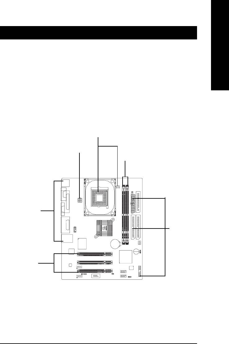
Step 1
Step 4
Step 2
Step 4
Step 4
Step 3
- 9 - Hardware Installation Process
Step 1: Install the Central Processing Unit (CPU)
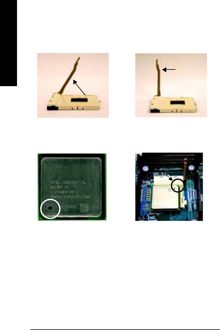
Step1-1: CPU Installation
English
Socket
Angling the
Actuation
0
rod to 65
Lever
1. Angling the rod to 65-degree maybe
2. Pull the rod to the 90-degree directly .
feel a kind of tight , and then continue
pull the rod to 90-degree when a noise
“cough” made.
Pin1 indicator
Pin1 indicator
3. CPU Top View
4. Locate Pin 1 in the socket and look
for a (golden) cut edge on the CPU
upper corner. Then insert the CPU
into the socket.
0 Please make sure the CPU type is supported by the motherboard.
00
00
0 If you do not match the CPU socket Pin 1 and CPU cut edge well, it will cause
00
00
improper installation. Please change the insert orientation.
- 10 -GA-8IMMT4 Motherboard
English
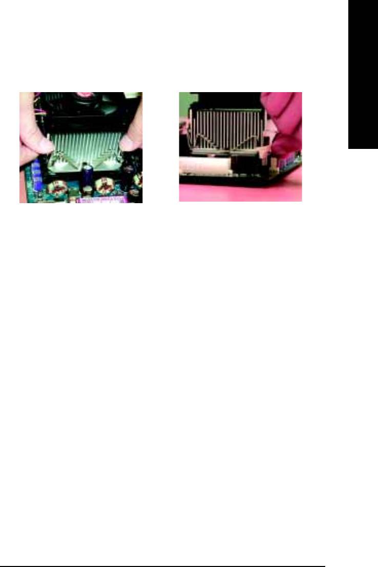
Step 1-2 : CPU Heat Sink Installation
1. Hook one end of the cooler bracket
2. Hook the other end of the cooler
to the CPU socket first.
bracket to the CPU socket.
00
00
0 Please use Intel approved cooling fan.
00
00
0 We recommend you to apply the thermal tape to provide better heat conduc-
tion between your CPU and heatsink.
(The CPU cooling fan might stick to the CPU due to the hardening of the
thermal paste. During this condition if you try to remove the cooling fan, you
might pull the processor out of the CPU socket alone with the cooling fan,
and might damage the processor. To avoid this from happening, we suggest
you to either use thermal tape instead of thermal paste, or remove the cooling
fan with extreme caution.)
00
00
0 Make sure the CPU fan power cable is plugged in to the CPU fan connector,
this completes the installation.
0 Please refer to CPU heat sink user’s manual for more detail installation
00
00
procedure.
- 11 - Hardware Installation Process
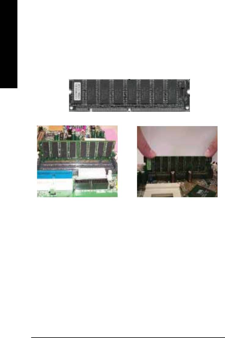
Step 2: Install memory modules
The motherboard has 2 dual in-line memory module (DIMM) sockets support 4 banks. The BIOS will
automatically detects memory type and size. To install the memory module, just push it vertically into
English
the DIMM socket. The DIMM module can only fit in one direction due to the two notch. Memory size
can vary between sockets.
SDRAM
1. The DIMM socket has two notch, so
2. Insert the DIMM memory module verti-
the DIMM memory module can only fit
cally into the DIMM socket. Then push
in one direction.
it down.
3. Close the plastic clip at both edges of the DIMM sockets to lock the DIMM module.
Reverse the installation steps when you wish to remove the DIMM module.
00
00
0 When RAM LED is ON, do not install/remove SDRAM from socket.
00
00
0 Please note that the DIMM module can only fit in one direction due to the two
notches. Wrong orientation will cause improper installation. Please change
the insert orientation.
- 12 -GA-8IMMT4 Motherboard
English
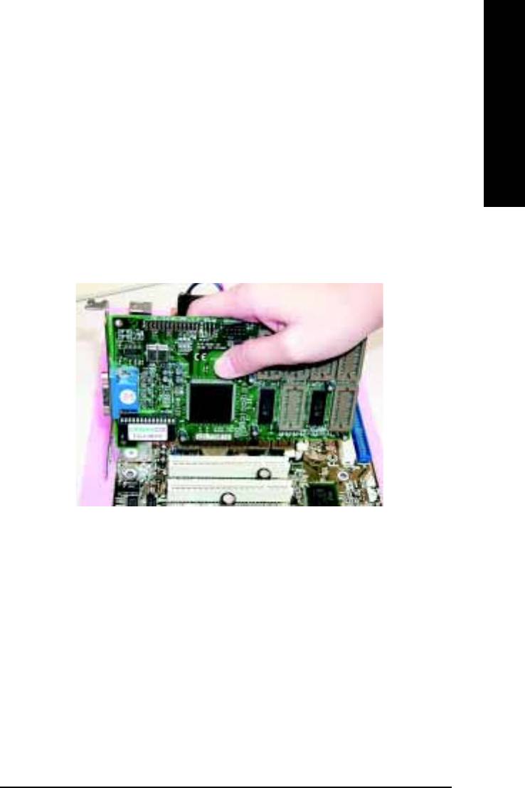
Step 3: Install expansion cards
1. Read the related expansion card’s instruction document before install the expansion card into
the computer.
2. Remove your computer’s chassis cover, screws and slot bracket from the computer.
3. Press the expansion card firmly into expansion slot in motherboard.
4. Be sure the metal contacts on the card are indeed seated in the slot.
5. Replace the screw to secure the slot bracket of the expansion card.
6. Replace your computer’s chassis cover.
7. Power on the computer, if necessary, setup BIOS utility of expansion card from BIOS.
8. Install related driver from the operating system.
- 13 - Hardware Installation Process
Step 4: Connect ribbon cables, cabinet wires and power
supply
English
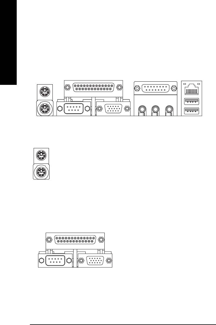
Step4-1 : I/O Back Panel Introduction
Y
Z
\
X
[
XX
XX
X PS/2 Keyboard and PS/2 Mouse Connector
PS/2 Mouse Connector
¾ This connector supports standard PS/2
(6 pin Female)
keyboard and PS/2 mouse.
PS/2 Keyboard Connector
(6 pin Female)
Y Parallel Port, Serial Ports and VGA port (LPT/COMA/VGA)
YY
YY
Parallel Port
(25 pin Female)
¾ This motherboard supports 1 standard COM
port, 1 LPT port and 1 VGA port. Device like
printer can be connected to LPT port; mouse
and modem etc. can be connected to COM
port.
COMA VGA
Serial Port
VGA Port
(9 pin Male)
(15 pin Female)
- 14 -GA-8IMMT4 Motherboard

English
ZZ
ZZ
Z Game /MIDI Ports
¾ This connector supports joystick, MIDI keyboard
and other relate audio devices.
Joystick / MIDI (15 pin Female)
[ Audio Connectors
[[
[[
¾ After install onboard audio driver, you may con-
nect speaker to Line Out jack, micro phone to
MIC In jack.
Device like CD-ROM, walkman etc. can be
connected to Line-In jack.
Line Out
MIC In
Line In
\ USB/LAN Connector
\\
\\
¾ Before you connect your device(s) into USB
connector(s), please make sure your device(s) such
LAN Connector
as USB keyboard, mouse, scanner, zip, speaker...
etc. Have a standard USB interface. Also make
USB 0
sure your OS supports USB controller. If your OS
USB 1
does not support USB controller, please contact
OS vendor for possible patch or driver upgrade. For
more information please contact your OS or
device(s) vendors.
- 15 - Hardware Installation Process
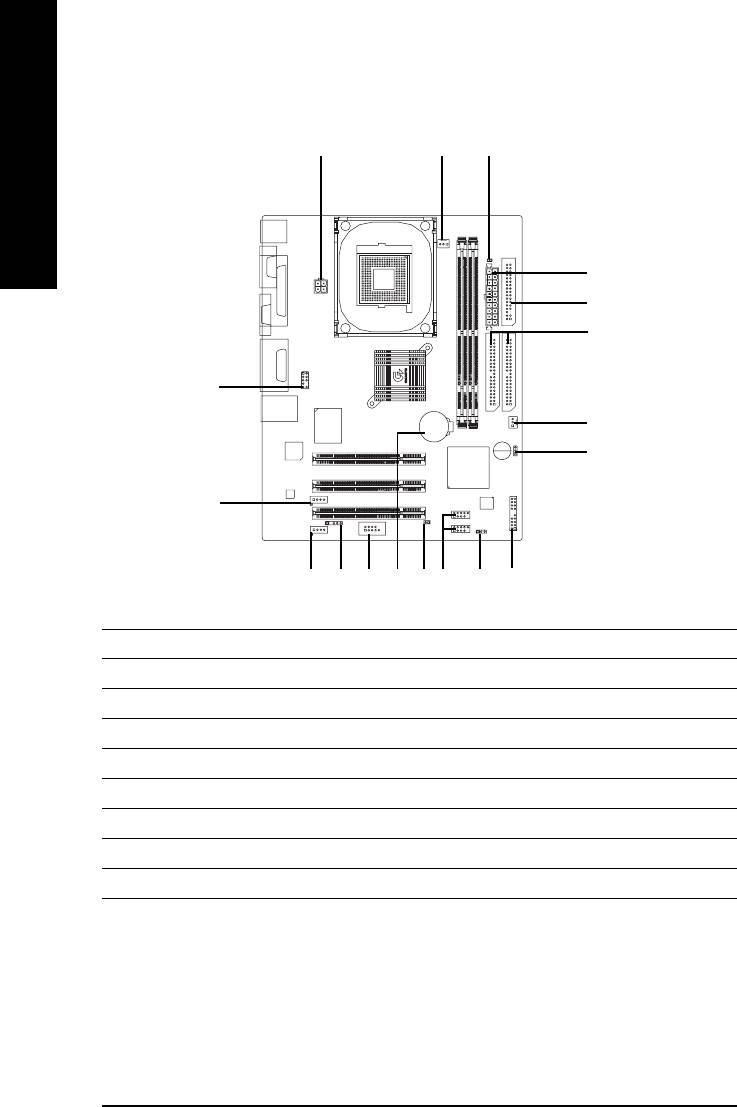
Step4-2 : Connectors Introduction
3 1
7
English
4
6
5
10
2
17
12
11
14 13
18
16
815
9
1) CPU_FAN
10) F_AUDIO
2) SYS_FAN
11) CD_IN
3) ATX_12V
12) AUX_IN
4) ATX
13) F_USB1 / F_USB2
5) IDE1 / IDE2
14) COMB
6) FDD
15) IR
7) DIMM_LED
16) CI
8) PWR_LED
17) CLR_COMS
9) F_PANEL
18) BAT1
- 16 -GA-8IMMT4 Motherboard
English
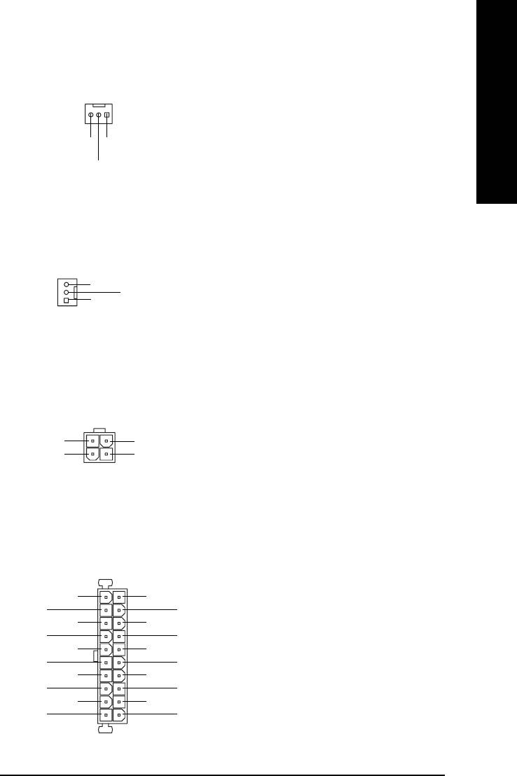
1) CPU_FAN (CPU FAN Connector)
¾ Please note, a proper installation of the CPU
cooler is essential to prevent the CPU from
running under abnormal condition or damaged
1
by overheating. The CPU fan connector sup-
ports Max. current up to 600 mA.
Sense
GND
+12V/Control
2) SYS_FAN (System FAN Connector)
¾ This connector allows you to link with the cool-
ing fan on the system case to lower the system
temperature.
Sense
+12V/Control
1
GND
3) ATX_12V (+12V Power Connector)
¾ This connector (ATX +12V) supplies the CPU
operation voltage (Vcore). If this "ATX+ 12V
3
4
connector" is not connected, system cannot
boot.
+12V
+12V
GND
GND
21
4) ATX (ATX Power Connector)
¾ AC power cord should only be connected to
your power supply unit after ATX power cable
1
and other related devices are firmly connected
3.3V
3.3V
to the motherboard.
-12V
3.3V
GND
GND
PS-ON
(Soft On/Off)
VCC
GND
GND
GND
VCC
GND
GND
-5V
Power Good
VCC
5V SB
(Stand by +5V)
VCC
+12V
20
- 17 - Hardware Installation Process
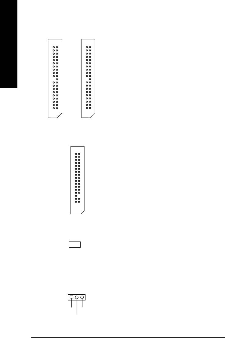
5) IDE1 / IDE2 (IDE1 / IDE2 Connector)
¾ Important Notice:
Please connect first hard disk to IDE1 and
connect CD-ROM to IDE2.
The red stripe of the ribbon cable must be the
English
same side with the Pin1.
1
1
IDE2
IDE1
6) FDD (Floppy Connector)
¾ Please connect the floppy drive ribbon cables
to FDD. It supports 360K, 1.2M, 720K, 1.44M
and 2.88M bytes floppy disk types.
The red stripe of the ribbon cable must be the
same side with the Pin1.
1
7) DIMM_LED
¾ Do not remove memory modules while
DIMM LED is on. It might cause short or other
unexpected damages due to the 3.3V stand
_
+
by voltage. Remove memory modules only
when STR function is disabled by jumper and
AC Power cord is disconnected.
8) PWR_LED
¾ PWR_LED is connect with the system power
indicator to indicate whether the system is
1
on/off. It will blink when the system enters
suspend mode.
MPD+
MPD-
If you use dual color LED, power LED will turn
MPD-
to another color.
- 18 -GA-8IMMT4 Motherboard
English
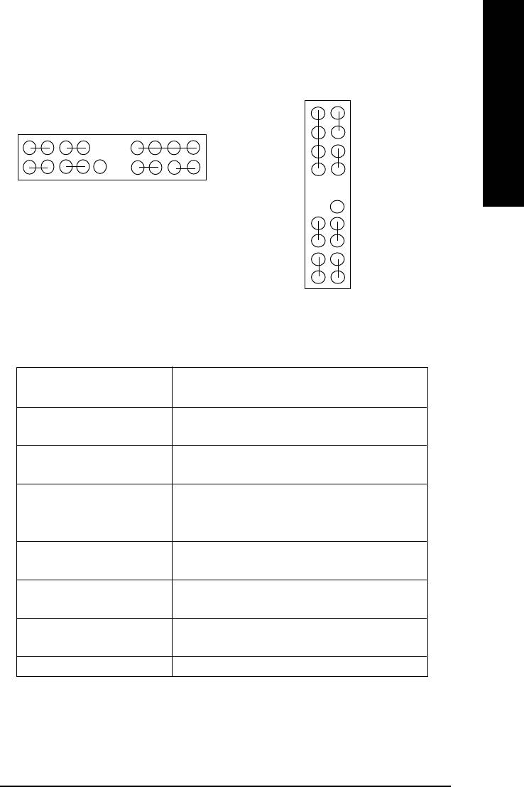
9) F_PANEL (2x10 Pins Connector)
20
19
SPK-
GN-
MSG+
MSG-
PW+
PW-
SPK+
SPK-
1
GN+
1
1
1
2
20
GD-
1
19
SPK+
1
1
GD+
1
1
1
1
HD+
HD-
NC
GD+
GD-
GN+
GN-
RST+
RST-
NC
PW-
RST-
In PCB ver. 1.0
PW+
1
1
RST+
MSG-
HD-
MSG+
1
1
HD+
2
1
In PCB ver. 1.1
GN (Green Switch) Open: Normal Operation
Close: Entering Green Mode
GD (Green LED) Pin 1: LED anode(+)
Pin 2: LED cathode(-)
HD (IDE Hard Disk Active LED) Pin 1: LED anode(+)
Pin 2: LED cathode(-)
SPK (Speaker Connector) Pin 1: VCC(+)
Pin 2- Pin 3: NC
Pin 4: Data(-)
RES (Reset Switch) Open: Normal Operation
Close: Reset Hardware System
PW (Soft Power Connector) Open: Normal Operation
Close: Power On/Off
MSG(Message LED/Power/ Pin 1: LED anode(+)
Sleep LED) Pin 2: LED cathode(-)
NC NC
¾ Please connect the power LED, PC speaker, reset switch and power switch etc of your chassis
front panel to the F_PANEL connector according to the pin assignment above.
- 19 - Hardware Installation Process
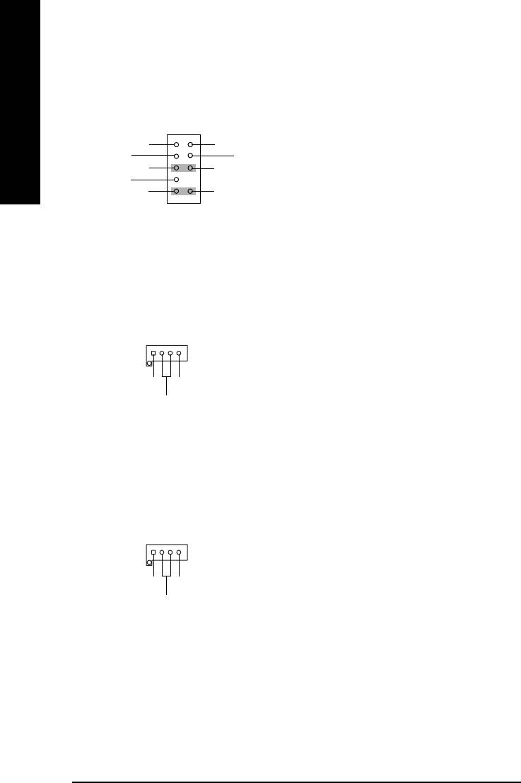
10) F_AUDIO (F_AUDIO Connector)
¾ If you want to use Front Audio connector, you
must remove 5-6, 9-10 Jumper.
In order to utilize the front audio header, your
1
chassis must have front audio connector. Also
English
MIC
GND
please make sure the pin assigment on the
REF
POWER
Front Audio (R)
cable is the same as the pin assigment on the
Rear Audio (R)
Reserved
MB header. To find out if the chassis you are
Front Audio (L)
Rear Audio (L)
buying support front audio connector, please
contact your dealer.
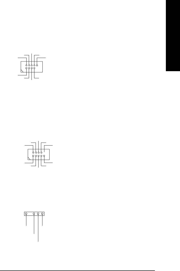
11) CD_IN (CD In Connector)
¾ Connect CD-ROM or DVD-ROM audio out to
the connector.
1
CD-L
CD-R
GND
12) AUX_IN (AUX In Connector)
¾ Connect other device (such as PCI TV Tunner
audio out) to the connector.
1
AUX-L
AUX-R
GND
- 20 -GA-8IMMT4 Motherboard
English
13) F_USB1 / F_USB2 (Front USB Connector)
(F_USB1 & F_USB2 connectors in yellow are for USB 2.0)
¾ Be careful with the polarity of the front USB
connector. Check the pin assignment while
USB Dy+
you connect the front USB cable. Please
USB Dy-
GND
Power
USB Over
Current
contact your nearest dealer for optional front
USB 2.0 cable.
1
Power
GND
USB Dx-
USB Dx+
14) COMB
¾ Be careful with the polarity of the COMB
connector. Check the pin assignment while
you connect the COMB cable. Please contact
your nearest dealer for optional COMB cable.
NDSRB-
NDTRB-
NCTSB-
NSINB
NC
1
NRIB-
NDCDB-
GND
NRTSB-
NSOUTB
15) IR
¾ Be careful with the polarity of the IR connector
while you connect the IR. Please contact your
1
nearest dealer for optional IR device.
VCC(+5V)
IR Data Output
IR Data Input
GND
- 21 - Hardware Installation Process
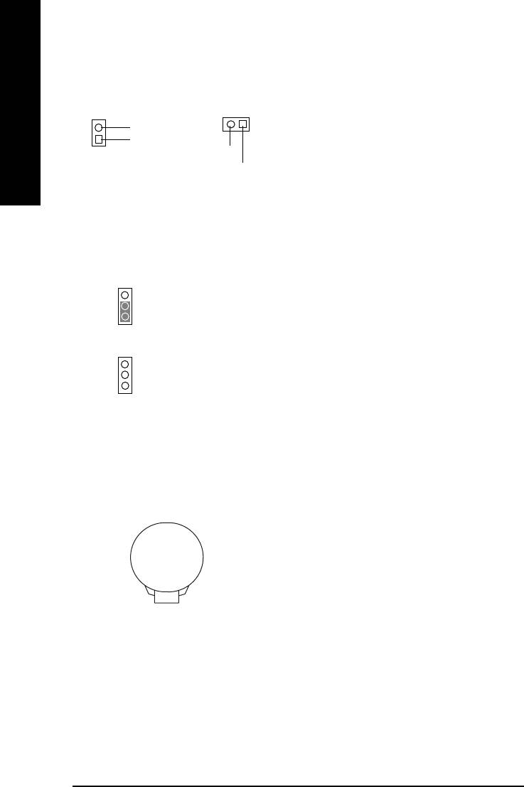
16) CI (CASE OPEN)
¾ This 2-pin connector allows your system to en-
able or disable the “Case Open” item in BIOS,
if the system case begin remove.
GND
1
English
1
Signal
GND
Signal
In PCB ver. 1.0 In PCB ver. 1.1
#
17) CLR_CMOS (Clear CMOS)
¾ You may clear the CMOS data to its default
values by this jumper.
1-2 close: Clear CMOS
To clear CMOS, temporarily short 1-2 pin.
1
# Default doesn’t include the “Shunter” to
prevent from improper use this jumper.
Open: Normal
1
18) BAT1 (Battery)
CAUTION
Danger of explosion if battery is incorrectly
replaced.
Replace only with the same or equivalent type
+
recommended by the manufacturer.
Dispose of used batteries according to the
manufacturer’s instructions.
- 22 -GA-8IMMT4 Motherboard

English
- 23 - Hardware Installation Process

English
- 24 -
Table of Content
Оглавление
- DECLARATION OF CONFORMITY
- Item Checklist
- Chapter 1 Introduction
- Chapter 2 Hardware Installation Process
- Chapter 3 BIOS Setup
- Chapter 4 Technical Reference
- Chapter 5 Appendix


