Gigabyte GA-8ILML4: Chapter 2 Hardware Installation Process
Chapter 2 Hardware Installation Process: Gigabyte GA-8ILML4
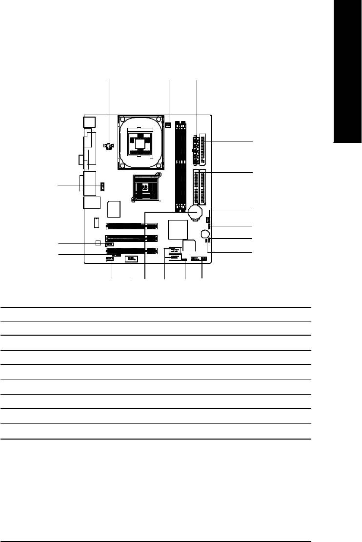
Chapter 2 Hardware Installation Process
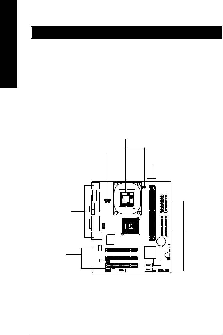
To set up your computer, you must complete the following steps:
English
Step 1- Install the Central Processing Unit (CPU)
Step 2- Install memory modules
Step 3- Connect ribbon cables, cabinet wires, and power supply
Step 4- Setup BIOS software
Step 5- Install supporting software tools
Step1
Step4
Step 2
Step 4
Step 4
Step3
- 8 -GA-8ILML4 Motherboard
English
Step 1: Install the Central Processing Unit (CPU)
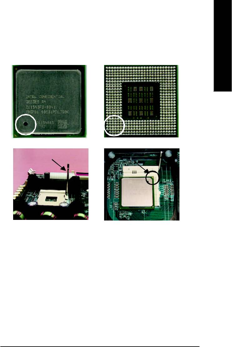
Step 1-1 : CPU Installation
Pin1 indicator
Pin1 indicator
CPU Top View CPU Bottom View
Socket Actuation Lever
Pin1 indicator
1. Pull up the CPU socket lever
2. Locate Pin 1 in the socket and look
and up to 90-degree angle.
for a (golden) cut edge on the CPU
upper corner. Then insert the CPU
3. Press down the CPU socket
into the socket.
lever and finish CPU installation.
M Please make sure the CPU type is supported by the motherboard.
M If you do not match the CPU socket Pin 1 and CPU cut edge well, it will cause
improper installation. Please change the insert orientation.
- 9 - Hardware Installation Process

Step 1-2 : CPU Heat Sink Installation
English
1. Hook one end of the cooler
2. Hook the other end of the
bracket to the CPU socket first.
cooler bracket to the CPU
socket.
M Please use Intel approved cooling fan.
M We recommend you to apply the thermal tape to provide better heat
conduction between your CPU and heatsink.
(The CPU cooling fan might stick to the CPU due to the hardening of the
thermal paste. During this condition if you try to remove the cooling fan, you
might pull the processor out of the CPU socket alone with the cooling fan, and
might damage the processor. To avoid this from happening, we suggest you to
either use thermal tape instead of thermal paste, or remove the cooling fan with
extreme caution.)
M Make sure the CPU fan power cable is plugged in to the CPU fan connector,
this completes the installation.
M Please refer to CPU heat sink user’s manual for more detail installation
procedure.
- 10 -GA-8ILML4 Motherboard
English
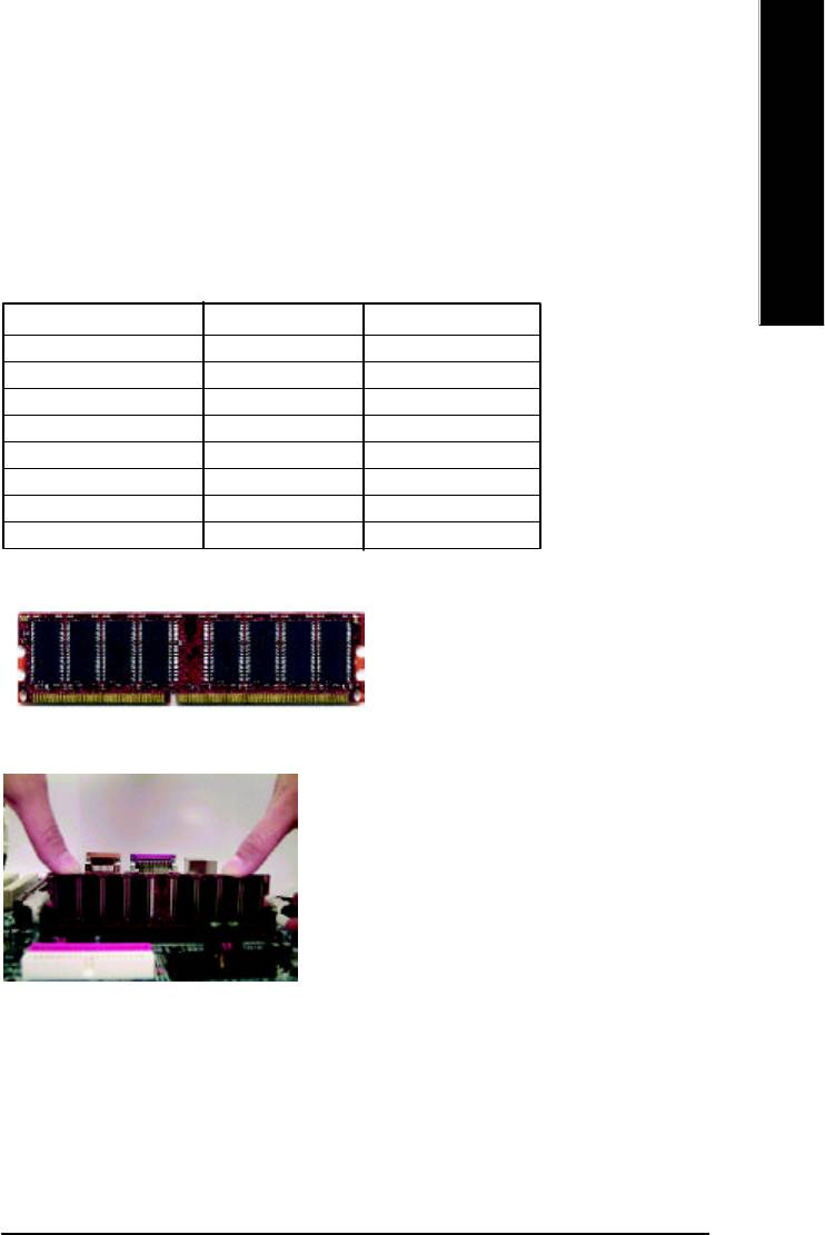
Step 2: Install memory modules
The motherboard has 2 dual inline memory module (DIMM) sockets. The BIOS will automatically
detects memory type and size. To install the memory module, just push it vertically into the DIMM Slot
.The DIMM module can only fit in one direction due to the notch. Memory size can vary between
sockets.
Total Memory Sizes With Unbuffered DDR DIMM
Devices used on DIMM 1 DIMM x 64 / x 72 2 DIMMs x 64 / x 72
64 Mbit (2Mx8x4 banks) 128 MBytes 256 MBytes
64 Mbit (1Mx16x4 banks) 32 MBytes 64 MBytes
128 Mbit(4Mx8x4 banks) 256 MBytes 512 MBytes
128 Mbit(2Mx16x4 banks) 64 MBytes 128 MBytes
256 Mbit(8Mx8x4 banks) 512 MBytes 1 GBytes
256 Mbit(4Mx16x4 banks) 128 MBytes 256 MBytes
512 Mbit(16Mx8x4 banks) 1 GBytes 2 GBytes
512 Mbit(8Mx16x4 banks) 256 MBytes 512 MBytes
Notes: Double-sided x16 DDR memory devices are not support by Intel 845E/G chipset.
DDR
1. The DIMM slot has a notch, so the
DIMMmemory module can only fit in one direction.
2. Insert the DIMM memory module vertically into the
DIMM slot. Then push it down.
3. Close the plastic clip at both edges of theDIMM slots
to lock the DIMM module.
Reverse the installation steps when you wish to
remove the DIMM module.
M When STR/DIMM LED is ON, you do not install / remove DDR from socket.
- 11 - Hardware Installation Process

DDR Introduction
Established on the existing SDRAM industry infrastructure, DDR (Double Data Rate) memory is a
high performance and cost-effective solution that allows easy adoption for memory vendors, OEMs and
system integrators.
English
DDR memory is a sensible evolutionary solution for the PC industry that builds on the existing
SDRAM infrastructure, yet makes awesome advances in solving the system performance bottleneck by
doubling the memory bandwidth. DDR SDRAM will offer a superior solution and migration path from
existing SDRAM designs due to its availability, pricing and overall market support. PC2100 DDR
memory (DDR266) doubles the data rate through reading and writing at both the rising and falling edge of
the clock, achieving data bandwidth 2X greater than PC133 when running with the same DRAM clock
frequency. With peak bandwidth of 2.1GB per second, DDR memory enables system OEMs to build
high performance and low latency DRAM subsystems that are suitable for servers, workstations, high-
end PC's and value desktop SMA systems. With a core voltage of only 2.5 Volts compared to
conventional SDRAM's 3.3 volts, DDR memory is a compelling solution for small form factor desktops
and notebook applications.
- 12 -GA-8ILML4 Motherboard
English
Step 3: Connect ribbon cables, cabinet wires, and power
supply
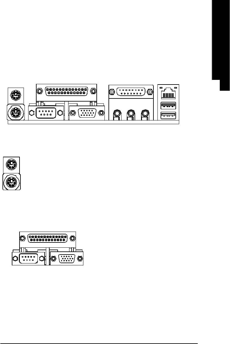
Step3-1 : I/O Back Panel Introduction
v w
y
u
x
u PS/2 Keyboard and PS/2 Mouse Connector
PS/2 Mouse Connector
ØThis connector supports standard PS/2
(6 pin Female)
keyboard and PS/2 mouse.
PS/2 Keyboard Connector
(6 pin Female)
v Parallel Port ,VGA port and Serial Ports (COMA)
Parallel Port
ØThis mainboard supports 1 standard COM port,
(25 pin Female)
1 VGA port and 1 LPT port. Device like printer
can be connected to LPT port ; mouse and
modem etc can be connected to COM port.
COMA VGA
Serial Port
VGA Port
(9 pin Male)
(15 pin Female)
- 13 - Hardware Installation Process

w Game /MIDI Ports
ØThis connector supports joystick, MIDI keyboard and other
relate audio devices.
English
Joystick/ MIDI (15 pin Female)
x Audio Connectors
Ø After install onboard audio driver, you may connect
speaker to Line Out jack, micro phone to MIC In jack.
Device like CD-ROM , walkman etc can be connected
to Line-In jack.
MIC InLine Out
Line In
y USB/LAN Connector
ØBefore you connect your device(s) into USB connector(s),
please make sure your device(s) such as USB keyboard,
LAN
mouse, scanner, zip,speaker..etc. Have a standard USB
Connector
interface. Also make sure your OS (Win 95 with USB
USB 0
supplement, Win98, Windows 2000, Windows ME, Win
USB 1
NT with SP 6) supports USB controller. If your OS does not
support USB controller, please contact OS vendor for pos-
sible patch or driver upgrade. For more information please
contact your OS or device(s) vendors.
- 14 -GA-8ILML4 Motherboard
English
Step 3-2 : Connectors Introduction
A
B
C
D
E
R
F
G
H
Q
P
I
MN L
KO
J
A) ATX_12V
J) F_PANEL
B) CPU_FAN
K) PWR_LED
C) ATX
L) F_USB1/F_USB2
D) FDD
M) BATTERY
E) IDE1/IDE2
N) COMB
F) SYS_FAN
O) CD_IN
G) CLR_CMOS
P) IR
H) BIOS_WP
Q) AUX_IN
I) CI
R) F_AUDIO
- 15 - Hardware Installation Process
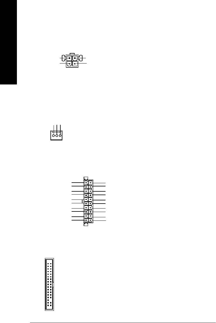
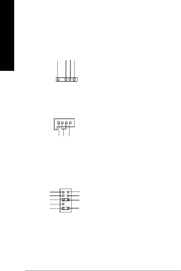
A) ATX_12V ( +12V Power Connector)
Ø This connector (ATX +12V) supplies the CPU
operation voltage (Vcore).
If this " ATX+ 12V connector" is not
3
4
connected, system cannot boot.
English
+12V
+12V
GND
GND
21
B) CPU_FAN (CPU FAN Connector)
Ø Please note, a proper installation of the CPU
cooler is essential to prevent the CPU from
running under abnormal condition or damaged
by overheating.The CPU fan connector
supports Max. current up to 600 mA.
Sense
+12V/Control
GND
1
C) ATX_POWER (ATX Power)
Ø AC power cord should only be connected to
your power supply unit after ATX power cable
and other related devices are firmly
1
connected to the mainboard.
3.3V
3.3V
-12V
3.3V
GND
GND
PS-ON(Soft On/Off)
VCC
GND
GND
GND
VCC
GND
GND
-5V
Power Good
VCC
5V SB (Stand by +5V)
VCC
+12V
20
D) FDD (Floppy Connector)
1
- 16 -GA-8ILML4 Motherboard
English
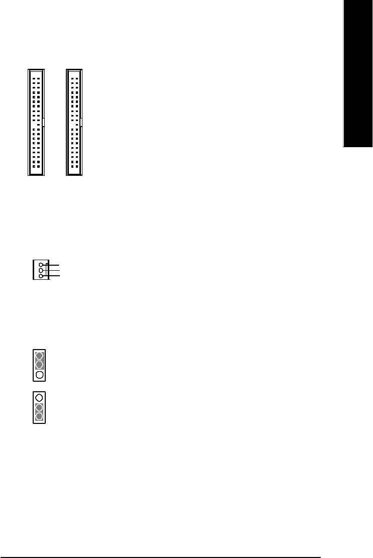
E) IDE1/ IDE2 (IDE1/IDE2 Connector)
Ø Important Notice:
Please connect first harddisk to IDE1
and connect CDROM to IDE2.
1
1
IDE1
IDE2
F) SYS_FAN (System FAN Connector)
Sense
+12V/Control
1
GND
G) CLR_CMOS (Clear CMOS)
Ø You may clear the CMOS data to its default
values by this jumper.
2-3 close: Normal
Default doesn’t include the “Shunter” to prevent
1
from improper use this jumper. To clear CMOS,
temporarily short 1-2 pin.
1-2 close: Clear CMOS
1
- 17 - Hardware Installation Process
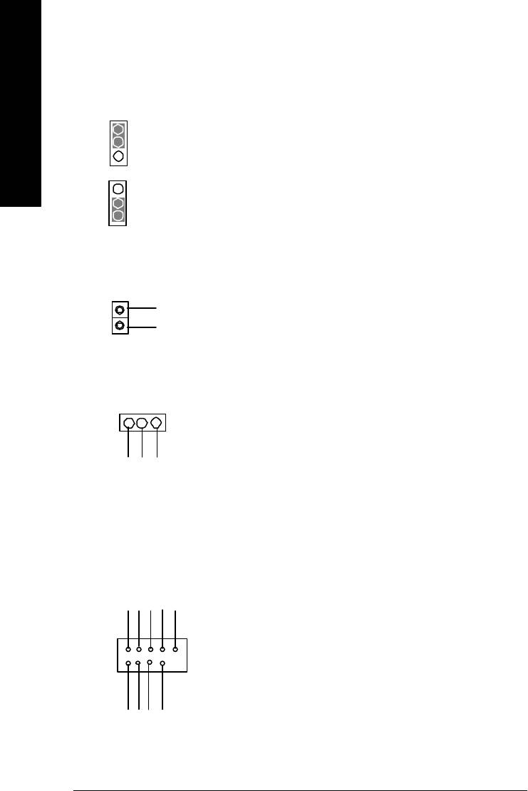
H) BIOS_WP (BIOS Write Protection)
Ø Please note, To flash/upgrade BIOS on this MB
BIOS_WP must be set to 2-3 close. We
recommend BIOS_WP to be set to "1-2 close",
English
2-3 close: Normal
whenever user does not need to flash/upgrade
1
the BIOS.
1-2 close: Write Protection
1
I) CI (CASE OPEN) Ø This 2 pin connector allows your system to
enable or disable the system alarm if the sys
tem case begin remove.
GND
1
Signal
K) PWR_LED
1
MPD+
MPD-
MPD-
L) F_USB1/F_USB2 (Front USB Connector)
Ø Be careful with the polarity of the front
panel USB connector. Check the pin
assignment while you connect the front
Power
USB Dy-
USB Dy+
GND
USB Over
Current
panel USB cable. Please contact your
nearest dealer for optional front panel
USB 2.0 cable.
1
GND
Power
USB Dx-
USB Dx+
- 18 -GA-8ILML4 Motherboard

English
M) BATTERY (Battery)
CAUTION
v Danger of explosion if battery is incorrectly
replaced.
v Replace only with the same or equivalent
type recommended by the manufacturer.
+
v Dispose of used batteries according to the
manufacturer’s instructions.
N) COM B
NSINB
NDTRB-
NDSRB-
NCTSB-
NC
1
GND
NRIB-
NRTSB-
NDCDB-
NSOUTB
O) CD_IN (CD IN)
1
GND
CD_-L
CD-R
- 19 - Hardware Installation Process
P) IR
Ø Be careful with the polarity of the IR
connectorwhile you connect the IR. Please
contact you nearest dealer for optional IR
English
device.
VCC(+5V)
IR Data Input
GND
IR Data Output
1
Q) AUX_IN ( AUX In Connector)
1
GND
AUX-L
AUX-R
R) F_AUDIO (F_AUDIO Connector)
Ø If you want to use Front Audio connector, you
must remove 5-6, 9-10 Jumper.
In order to utilize the front audio header, your
chassis must have front audio connector. Also
1
please make sure the pin assigment on the cable
MIC
GND
REF
POWER
is the same as the pin assigment on the MB
Front Audio (R)
Rear Audio (R)
Reserved
header. To find out if the chassis you are buying
Front Audio (L)
Rear Audio (L)
support front audio connector, please contact
your dealer.
- 20 -GA-8ILML4 Motherboard
English
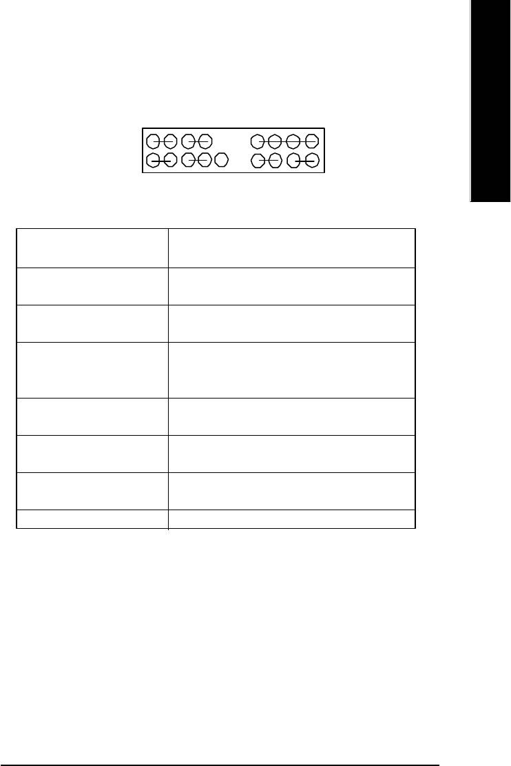
J) F_PANEL (2x10 pins connector)
MPD+
MPD-
PW+
PW-
SPK+
SPK-
1
1
1
2
20
1 19
1
1
1
1
HD+
HD-
RST-
GD+
GD-
GN+
GN-
RST+
NC
GN (Green Switch) Open: Normal Operation
Close: Entering Green Mode
GD (Green LED) Pin 1: LED anode(+)
Pin 2: LED cathode(-)
HD (IDE Hard Disk Active LED) Pin 1: LED anode(+)
Pin 2: LED cathode(-)
SPK (Speaker Connector) Pin 1: VCC(+)
Pin 2- Pin 3: NC
Pin 4: Data(-)
RE (Reset Switch) Open: Normal Operation
Close: Reset Hardware System
PW (Soft Power Connector) Open: Normal Operation
Close: Power On/Off
MPD(Message LED/Power/ Pin 1: LED anode(+)
Sleep LED) Pin 2: LED cathode(-)
NC NC
Ø Please connect the power LED, PC speaker, reset switch and power switch etc of your chassis
front panel to the F_PANEL connector according to the pin assignment above.
- 21 - Hardware Installation Process

Chapter 3 BIOS Setup
BIOS Setup is an overview of the BIOS Setup Program. The program that allows users to modify the
basic system configuration. This type of information is stored in battery-backed CMOS RAM so that it
English
retains the Setup information when the power is turned off.
ENTERING
SETUP
Powering ON the computer and pressing <Del> immediately will allow you to enter Setup. If you require
more advanced BIOS settings, please go to “Advanced BIOS” setting menu.To enter Advanced BIOS
setting menu, press “Ctrl+F1” key on the BIOS screen.
CONTROL
KEYS
<á> Move to previous item
<â> Move to next item
<ß> Move to the item in the left hand
<à> Move to the item in the right hand
<Esc> Main Menu - Quit and not save changes into CMOS Status Page Setup Menu and
Option Page Setup Menu - Exit current page and return to Main Menu
<+/PgUp> Increase the numeric value or make changes
<-/PgDn> Decrease the numeric value or make changes
<F1> General help, only for Status Page Setup Menu and Option Page Setup Menu
<F2> Item help
<F3> Reserved
<F4> Reserved
<F5> Restore the previous CMOS value from CMOS, only for Option Page Setup Menu
<F6> Load the file-safe default CMOS value from BIOS default table
<F7> Load the Optimized Defaults
<F8> Q-Flash function
<F9> Reserved
<F10> Save all the CMOS changes, only for Main Menu
- 22 -GA-8ILML4 Motherboard

English
GETTING HELP
Main Menu
The on-line description of the highlighted setup function is displayed at the bottom of the screen.
Status Page Setup Menu / Option Page Setup Menu
Press F1 to pop up a small help window that describes the appropriate keys to use and the possible
selections for the highlighted item. To exit the Help Window press <Esc>.
The Main Menu (For example: BIOS Ver. : F1b)
Once you enter Award BIOS CMOS Setup Utility, the Main Menu (Figure 1) will appear on the screen.
The Main Menu allows you to select from eight setup functions and two exit choices. Use arrow keys to
select among the items and press <Enter> to accept or enter the sub-menu.
CMOS Setup Utility-Copyright (C) 1984-2002 Award Software
}Standard CMOS Features Top Performance
}Advanced BIOS Features Load Fail-Safe Defaults
}Integrated Peripherals Load Optimized Defaults
}Power Management Setup Set Supervisor Password
}PnP/PCI Configurations Set User Password
}PC Health Status Save & Exit Setup
}Frequency/Voltage Control Exit Without Saving
ESC:Quit higf:Select Item
F8: Q-Flash F10:Save & Exit Setup
Time, Date, Hard Disk Type...
Figure 1: Main Menu
l Standard CMOS Features
This setup page includes all the items in standard compatible BIOS.
l Advanced BIOS Features
This setup page includes all the items of Award special enhanced features.
- 23 - BIOS Setup

l Integrated Peripherals
This setup page includes all onboard peripherals.
l Power Management Setup
English
This setup page includes all the items of Green function features.
l PnP/PCI Configurations
This setup page includes all the configurations of PCI & PnP ISA resources.
l PC Health Status
This setup page is the System auto detect Temperature, voltage, fan, speed.
l Frequency/Voltage Control
This setup page is control CPU’s clock and frequency ratio.
l Top Performance
If you wish to maximize the performance of your system, set "Top Performance" as "Enabled".
l Load Fail-Safe Defaults
Fail-Safe Defaults indicates the value of the system parameters which the system would
be in safe configuration.
l Load Optimized Defaults
Optimized Defaults indicates the value of the system parameters which the system would
be in best performance configuration.
l Set Supervisor password
Change, set, or disable password. It allows you to limit access to the system and Setup,
or just to Setup.
l Set User password
Change, set, or disable password. It allows you to limit access to the system.
l Save & Exit Setup
Save CMOS value settings to CMOS and exit setup.
l Exit Without Saving
Abandon all CMOS value changes and exit setup.
- 24 -GA-8ILML4 Motherboard

English
Standard CMOS Features
CMOS Setup Utility-Copyright (C) 1984-2002 Award Software
Standard CMOS Features
Date (mm:dd:yy) Mon, Feb 21 2000 Item Help
Time (hh:mm:ss) 22:31:24 Menu Level u
Change the day, month,
}IDE Primary Master None year
}IDE Primary Slave None
}IDE Secondary Master None <Week>
}IDE Secondary Slave None Sun. to Sat.
Drive A 1.44M, 3.5 in. <Month>
Drive B None Jan. to Dec.
Floppy 3 Mode Support Disabled
<Day>
Halt On All, But Keyboard 1 to 31 (or maximum
allowed in the month)
Base Memory 640K
Extended Memory 130048K <Year>
Total Memory 131072K 1999 to 2098
higf: Move Enter:Select +/-/PU/PD:Value F10:Save ESC:Exit F1:General Help
F5:Previous Values F6:Fail-Safe Defaults F7:Optimized Defaults
Figure 2: Standard CMOS Features
C Date
The date format is <week>, <month>, <day>, <year>.
8Week The week, from Sun to Sat, determined by the BIOS and is display only
8Month The month, Jan. Through Dec.
8 Day The day, from 1 to 31 (or the maximum allowed in the month)
8Year The year, from 1999 through 2098
- 25 - BIOS Setup

C Time
The times format in <hour> <minute> <second>. The time is calculated base on the 24-hour military-
time clock. For example, 1 p.m. is 13:00:00.
English
C IDE Primary Master, Slave / IDE Secondary Master, Slave
The category identifies the types of hard disk from drive C to F that has been installed in the computer.
There are two types: auto type, and manual type. Manual type is user-definable; Auto type which will
automatically detect HDD type.
Note that the specifications of your drive must match with the drive table. The hard disk will not work
properly if you enter improper information for this category.
If you select User Type, related information will be asked to enter to the following items. Enter the
information directly from the keyboard and press <Enter>. Such information should be provided in the
documentation form your hard disk vendor or the system manufacturer.
8CYLS. Number of cylinders
8HEADS Number of heads
8PRECOMP Write precomp
8LANDZONE Landing zone
8SECTORSNumber of sectors
If a hard disk has not been installed select NONE and press <Enter>.
C Drive A / Drive B
The category identifies the types of floppy disk drive A or drive B that has been installed in the
computer.
8None No floppy drive installed
8360K, 5.25 in. 5.25 inch PC-type standard drive; 360K byte capacity.
81.2M, 5.25 in. 5.25 inch AT-type high-density drive; 1.2M byte capacity
(3.5 inch when 3 Mode is Enabled).
8720K, 3.5 in. 3.5 inch double-sided drive; 720K byte capacity
81.44M, 3.5 in. 3.5 inch double-sided drive; 1.44M byte capacity.
82.88M, 3.5 in. 3.5 inch double-sided drive; 2.88M byte capacity.
- 26 -GA-8ILML4 Motherboard

English
C Floppy 3 Mode Support (for Japan Area)
8Disabled Normal Floppy Drive. (Default value)
8Drive A Drive A is 3 mode Floppy Drive.
8Drive B Drive B is 3 mode Floppy Drive.
8Both Drive A & B are 3 mode Floppy Drives.
CHalt on
The category determines whether the computer will stop if an error is detected during power up.
8NO Errors The system boot will not stop for any error that may be detected
and you will be prompted.
8All Errors Whenever the BIOS detects a non-fatal error the system will be stopped.
8All, But Keyboard The system boot will not stop for a keyboard error; it will stop for
all other errors. (Default value)
8All, But Diskette The system boot will not stop for a disk error; it will stop for all
other errors.
8All, But Disk/Key The system boot will not stop for a keyboard or disk error; it will
stop for all other errors.
C Memory
The category is display-only which is determined by POST (Power On Self Test) of the BIOS.
Base Memory
The POST of the BIOS will determine the amount of base (or conventional)
memory installed in the system.
The value of the base memory is typically 512 K for systems with 512 K
memory installed on the motherboard, or 640 K for systems with 640 K or
more memory installed on the motherboard.
Extended Memory
The BIOS determines how much extended memory is present during the
POST.
This is the amount of memory located above 1 MB in the CPU’s memory
address map.
- 27 - BIOS Setup

Advanced BIOS Features
CMOS Setup Utility-Copyright (C) 1984-2002 Award Software
Advanced BIOS Features
English
First Boot Device Floppy Item Help
Second Boot Device HDD-0 Menu Level u
Third Boot Device CDROM
Boot Up Floppy Seek Disabled
Init Display First Onboard/AGP
Graphics Aperture Size 128MB
Graphics Share Memory 8MB
higf: Move Enter:Select +/-/PU/PD:Value F10:Save ESC:Exit F1:General Help
F5:Previous Values F6:Fail-Safe Defaults F7:Optimized Defaults
Figure 3: Advanced BIOS Features
C First / Second / Third Boot Device
8Floppy Select your boot device priority by Floppy.
8LS120 Select your boot device priority by LS120.
8HDD-0~3 Select your boot device priority by HDD-0~3.
8SCSI Select your boot device priority by SCSI.
8CDROM Select your boot device priority by CDROM.
8ZIP Select your boot device priority by ZIP.
8USB-FDD Select your boot device priority by USB-FDD.
8USB-ZIP Select your boot device priority by USB-ZIP.
8USB-CDROM Select your boot device priority by USB-CDROM.
8USB-HDD Select your boot device priority by USB-HDD.
8LAN Select your boot device priority by LAN.
8Disabled Select your boot device priority by Disabled.
- 28 -GA-8ILML4 Motherboard

English
C Boot Up Floppy Seek
During POST, BIOS will determine the floppy disk drive installed is 40 or 80 tracks. 360 K type is
40 tracks 720 K, 1.2 M and 1.44 M are all 80 tracks.
8Enabled BIOS searches for floppy disk drive to determine it is 40 or 80 tracks. Note
that BIOS can not tell from 720 K, 1.2 M or 1.44 M drive type as they are
all 80tracks.
8Disabled BIOS will not search for the type of floppy disk drive by track number. Note
that there will not be any warning message if the drive installed is 360 K.
(Default value)
CInit Display First
8Onboard/AGP Set Init Display First to onboard/AGP. (Default value)
8PCI Set Init Display First to PCI.
CGraphics Aperture Size
8128MB Set Graphics Aperture Size to 128MB. (Default value)
8Disabled Disable this function.
CGraphics Share Memory
88MB Set Graphics Share Memory to 8MB. (Default value)
81MB Set Graphics Share Memory to 1MB.
- 29 - BIOS Setup

Integrated Peripherals
CMOS Setup Utility-Copyright (C) 1984-2002 Award Software
Integrated Peripherals
English
On-Chip Primary PCI IDE Enabled Item Help
On-Chip Secondary PCI IDE Enabled Menu Level u
IDE1 Conductor Cable Auto If a hard disk
IDE2 Conductor Cable Auto controller card is
USB Controller Enabled used, set at Disable
USB Keyboard Support Disabled
USB Mouse Support Disabled [Enabled]
AC97 Audio Auto Enable onboard IDE
Onboard LAN Enabled PORT
Onboard LAN Boot ROM Disabled
Onboard Serial Port 1 3F8/IRQ4
Onboard Serial Port 2 2F8/IRQ3
UART Mode Select Normal
x UR2 Duplex Mode Half [Disabled]
Onboard Parallel Port 378/IRQ7 Disable onboard IDE
Parallel Port Mode SPP PORT
Game Port Address 201
Midi Port Address 330
Midi Port IRQ 10
higf: Move Enter:Select +/-/PU/PD:Value F10:Save ESC:Exit F1:General Help
F5:Previous Values F6:Fail-Safe Defaults F7:Optimized Defaults
Figure 4: Integrated Peripherals
C On-Chip Primary PCI IDE
8Enabled Enable onboard 1st channel IDE port. (Default value)
8Disabled Disable onboard 1st channel IDE port.
- 30 -GA-8ILML4 Motherboard

English
C On-Chip Secondary PCI IDE
8Enabled Enable onboard 2nd channel IDE port. (Default value)
8Disabled Disable onboard 2nd channel IDE port.
C IDE1 Conductor Cable
8Auto Will be automatically detected by BIOS. (Default Value)
8ATA66/100 Set IDE1 Conductor Cable to ATA66/100 (Please make sure your IDE device
and cable is compatible with ATA66/100).
8ATA33 Set IDE1 Conductor Cable to ATA33 (Please make sure your IDE device and
cable is compatible with ATA33).
C IDE2 Conductor Cable
8Auto Will be automatically detected by BIOS. (Default Value)
8ATA66/100 Set IDE2 Conductor Cable to ATA66/100 (Please make sure your IDE device
and cable is compatible with ATA66/100).
8ATA33 Set IDE2 Conductor Cable to ATA33 (Please make sure your IDE device and
cable is compatible with ATA33).
C USB Controller
8Enabled Enable USB Controller. (Default value)
8Disabled Disable USB Controller.
C USB Keyboard Support
8Enabled Enable USB Keyboard Support.
8Disabled Disable USB Keyboard Support. (Default value)
C USB Mouse Support
8Enabled Enable USB Mouse Support.
8Disabled Disable USB Mouse Support. (Default value)
- 31 - BIOS Setup

C AC97 Audio
8Auto Enable onboard AC'97 audio function. (Default Value)
8Disabled Disable this function.
English
C Onboard LAN
8Enabled Enabled Onboard LAN function. (Default value)
8Disabled Disabled onboard LAN function.
C Onboard LAN Boot ROM
8Enabled Enabled Onboard LAN Boot ROM function.
8Disabled Disabled onboard LAN Boot ROM function.(Default value)
C Onboard Serial Port 1
8Auto BIOS will automatically setup the port 1 address.
83F8/IRQ4 Enable onboard Serial port 1 and address is 3F8. (Default value)
82F8/IRQ3 Enable onboard Serial port 1 and address is 2F8.
83E8/IRQ4 Enable onboard Serial port 1 and address is 3E8.
82E8/IRQ3 Enable onboard Serial port 1 and address is 2E8.
8Disabled Disable onboard Serial port 1.
C Onboard Serial Port 2
8Auto BIOS will automatically setup the port 2 address.
83F8/IRQ4 Enable onboard Serial port 2 and address is 3F8.
82F8/IRQ3 Enable onboard Serial port 2 and address is 2F8. (Default value)
83E8/IRQ4 Enable onboard Serial port 2 and address is 3E8.
82E8/IRQ3 Enable onboard Serial port 2 and address is 2E8.
8Disabled Disable onboard Serial port 2.
C UART Mode Select
(This item allows you to determine which Infra Red(IR) function of Onboard I/O chip)
8ASKIR Set onboard I/O chip UART to ASKIR Mode.
8IrDA Set onboard I/O chip UART to IrDA Mode.
8Normal Set onboard I/O chip UART to Normal Mode. (Default Value)
- 32 -GA-8ILML4 Motherboard

English
C UR2 Duplex Mode
8Half IR Function Duplex Half. (Default Value)
8Full IR Function Duplex Full.
C Onboard Parallel port
8378/IRQ7 Enable onboard LPT port and address is 378/IRQ7. (Default Value)
8278/IRQ5 Enable onboard LPT port and address is 278/IRQ5.
8Disabled Disable onboard LPT port.
83BC/IRQ7 Enable onboard LPT port and address is 3BC/IRQ7.
CParallel Port Mode
8SPP Using Parallel port as Standard Parallel Port. (Default Value)
8EPP Using Parallel port as Enhanced Parallel Port.
8ECP Using Parallel port as Extended Capabilities Port.
8ECP+EPP Using Parallel port as ECP & EPP mode.
CECP Mode Use DMA
83 Set ECP Mode Use DMA to 3. (Default Value)
81 Set ECP Mode Use DMA to 1.
CGame Port Address
8201 Set Game Port Address to 201. (Default Value)
8209 Set Game Port Address to 209.
8Disabled Disable this function.
CMidi Port Address
8300 Set Midi Port Address to 300.
8330 Set Midi Port Address to 330.(Default Value)
8Disabled Disable this function.
CMidi Port IRQ
85 Set Midi Port IRQ to 5.
810 Set Midi Port IRQ to 10. (Default Value)
- 33 - BIOS Setup

Power Management Setup
CMOS Setup Utility-Copyright (C) 1984-2002 Award Software
Power Management Setup
English
ACPI Suspend Type S1(POS) Item Help
Power LED in S1 State Blinking
Soft-Off by PWR_BTTN Instant-Off Menu Level u
PME Event Wake Up Enabled [S1]
ModemRingOn/WakeOnLan Enabled
Resume by Alarm Disabled Set suspend type to
x Date (of Month) Alarm Everyday Power On Suspend under
x Time (hh:nn:ss) Alarm 0 0 0 ACPI OS
Power On By Mouse Disabled
Power On By Keyboard Disabled [S3]
x KB Power ON Password Enter Set suspend type to
AC Back Function Soft-Off Suspend to RAM under
ACPI OS
higf: Move Enter:Select +/-/PU/PD:Value F10:Save ESC:Exit F1:General Help
F5:Previous Values F6:Fail-Safe Defaults F7:Optimized Defaults
Figure 5: Power Management Setup
C ACPI Suspend Type
This option will not be shown or not be available if you are using a CPU with the locked ratio.
8S1(POS) Set ACPI suspend type to S1. (Default Value)
8S3(STR) Set ACPI suspend type to S3.
C Power LED in S1 State
8Blinking In standby mode(S1), power LED will blink. (Default Value)
8Dual/Off In standby mode(S1):
a. If use single color LED, power LED will turn off.
b. If use dual color LED, power LED will turn to another color.
- 34 -GA-8ILML4 Motherboard

English
C Soft-off by PWR_BTTN
8Instant-off Press power button then Power off instantly. (Default value)
8Delay 4 Sec. Press power button 4 sec to Power off. Enter suspend if button is pressed less
than 4 sec.
C PME Event Wake Up
8Disabled Disable this function.
8Enabled Enable PME Event Wake up. (Default Value)
C ModemRingOn/WakeOnLAN
8Disabled Disable Modem Ring on/wake on Lan function.
8Enabled Enable Modem Ring on/wake on Lan. (Default Value)
C Resume by Alarm
You can set "Resume by Alarm" item to enabled and key in Data/time to power on system.
8Disabled Disable this function. (Default Value)
8Enabled Enable alarm function to POWER ON system.
If RTC Alarm Lead To Power On is Enabled.
Date ( of Month) Alarm : Everyday, 1~31
Time ( hh: mm: ss) Alarm : (0~23) : (0~59) : (0~59)
C Power On By Mouse
8Disabled Disabled this function. (Default value)
8Mouse Click Double click on PS/2 mouse left button.
C Power On By Keyboard
8 Password Enter from 1 to 5 characters to set the Keyboard Power On Password.
8Disabled Disabled this function. (Default value)
8Keyboard 98 If your keyboard have “POWER Key” button, you can press the key to
power on your system.
- 35 - BIOS Setup

CKB Power ON Password
8Enter Input password (from 1 to 5 characters) and press Enter to set the Key
board Power On Password.
English
CAC Back Function
8 Memory System power on depends on the status before AC lost.
8Soft-Off Always in Off state when AC back. (Default value)
8Full-On Always power on the system when AC back.
- 36 -GA-8ILML4 Motherboard

English
PnP/PCI Configurations
CMOS Setup Utility-Copyright (C) 1984-2002 Award Software
PnP/PCI Configurations
PCI 1 IRQ Assignment Auto Item Help
PCI 2 IRQ Assignment Auto Menu Level u
PCI 3 IRQ Assignment Auto
higf: Move Enter:Select +/-/PU/PD:Value F10:Save ESC:Exit F1:General Help
F5:Previous Values F6:Fail-Safe Defaults F7:Optimized Defaults
Figure 6: PnP/PCI Configurations
C PCI 1 IRQ Assignment
8Auto Auto assign IRQ to PCI. (Default value)
83,4,5,7,9,10,11,12,14,15 Set IRQ 3,4,5,7,9,10,11,12,14,15 to PCI 1/PCI 5.
C PCI 2 IRQ Assignment
8Auto Auto assign IRQ to PCI 2. (Default value)
83,4,5,7,9,10,11,12,14,15 Set IRQ 3,4,5,7,9,10,11,12,14,15 to PCI 2.
C PCI 3 IRQ Assignment
8Auto Auto assign IRQ to PCI 3. (Default value)
83,4,5,7,9,10,11,12,14,15 Set IRQ 3,4,5,7,9,10,11,12,14,15 to PCI 3.
- 37 - BIOS Setup

PC Health Status
CMOS Setup Utility-Copyright (C) 1984-2002 Award Software
PC Health Status
English
Reset Case Open Status Disabled Item Help
Case Opened No Menu Level u
VCORE 1.730V
+1.5V 1.502V
+3.3V 3.360V
+5V 5.053V
+12V 11.840V
Current CPU Temperature 35°C/95°F
Current CPU FAN Speed 6490 RPM
Current SYSTEM FAN Speed 0 RPM
CPU Warning Temperature Disabled
CPU FAN Fail Warning Disabled
SYSTEM FAN Fail Warning Disabled
higf: Move Enter:Select +/-/PU/PD:Value F10:Save ESC:Exit F1:General Help
F5:Previous Values F6:Fail-Safe Defaults F7:Optimized Defaults
Figure 7: PC Health Status
CReset Case Open Status
CCase Opened
If the case is closed, "Case Opened" will show "No".
If the case have been opened, "Case Opened" will show "Yes".
If you want to reset "Case Opened" value, set "Reset Case Open Status" to
"Enabled" and save CMOS, your computer will restart.
Disabled : Don’t reset case open status.;Enabled : Clear case open status at next boot.
C Current Voltage (V) VCORE / 1.5V /+3.3V / +5V / +12V
8Detect system’s voltage status automatically.
- 38 -GA-8ILML4 Motherboard

English
CCurrent CPU Temperature
8Detect CPU Temp. automatically.
C Current CPU/SYSTEM FAN Speed (RPM)
8Detect CPU/SYSTEM Fan speed status automatically.
C CPU Warning Temperature
860°C / 140°F Monitor CPU Temp. at 60°C / 140°F.
870°C / 158°F Monitor CPU Temp. at 70°C / 158°F.
880°C / 176°F Monitor CPU Temp. at 80°C / 176°F.
890°C / 194°F Monitor CPU Temp. at 90°C / 194°F.
8Disabled Disable this function.(Default value)
C CPU FAN Fail Warning
8Disabled Fan Warning Function Disable. (Default value)
8Enabled Fan Warning Function Enable.
C SYSTEM FAN Fail Warning
8Disabled Fan Warning Function Disable. (Default value)
8Enabled Fan Warning Function Enable.
- 39 - BIOS Setup

Frequency/Voltage Control
CMOS Setup Utility-Copyright (C) 1984-2002 Award Software
Frequency/Voltage Control
English
CPU Clock Ratio 15X Item Help
CPU Host Clock Control Disabled Menu Level u
x CPU Host Frequency (Mhz) 100
x PCI/AGP Divider Disabled
Host/DRAM Clock ratio Auto
Memory Frequency (Mhz) 266
PCI/AGP Frequency (Mhz) 33/66
higf: Move Enter:Select +/-/PU/PD:Value F10:Save ESC:Exit F1:General Help
F5:Previous Values F6:Fail-Safe Defaults F7:Optimized Defaults
Figure 7: Frequency/Voltage Control
CCPU Clock Ratio
This option will not be shown or not be available if you are using a CPU with the locked ratio.
810X~24X It’s depends on CPU Clock Ratio.
CCPU Host Clock Control
Note: If system hangs up before enter CMOS setup utility, wait for 20 sec for times out reboot . When
time out occur, system will reset and run at CPU default Host clock at next boot.
8Disable Disable CPU Host Clock Control.(Default value)
8Enable Enable CPU Host Clock Control.
CCPU Host Frequency
8100MHz ~ 355MHz Set CPU Host Clock from 100MHz to 355MHz.
- 40 -GA-8ILML4 Motherboard

English
CPCI/AGP Divider
8You can choose Disabled,PLL/40,PLL/32,PLL/24,PLL/20/PLL/16 mode to adjust PCI/AGP
frequency.
CHost/DRAM Clock Ratio
(Warning: wrong frequency may make system can’t boot, clear CMOS to overcome wrong fre
quency issue)
82.0 Memory Frequency = Host clock X 2.0.
82.66 Memory Frequency = Host clock X 2.66.
8Auto Set Memory frequency by DRAM SPD data. (Default value)
C Memory Frequency(Mhz)
8The values depend on CPU Host Frequency(Mhz) .
C PCI/AGP Frequency(Mhz)
8Setup PCI/AGP frequency by adjusting CPU Host Frequency or PCI/AGP Divider item.
- 41 - BIOS Setup

Top Performance
CMOS Setup Utility-Copyright (C) 1984-2002 Award Software
}Standard CMOS Features Top Performance
English
}Advanced Chipset Features Load Fail-Safe Defaults
Top Performance
}Integrated Peripherals Load Optimized Defaults
}Power Management Setup Set Supervisor Password
Disabled...................[n]
}PnP/PCI Configurations Set User Password
Enabled...................[ ]
}PC Health Status Save & Exit Setup
}Frequency/Voltage Control Exit Without Saving
ESC:Quit F3: Select Language
hi: Move ENTER: Accept
F8: Q-Flash F10:Save & Exit Setup
ESC: Abort
Figure 8: Top Performance
Top Performance
If you wish to maximize the performance of your system, set "Top Performance" as "Enabled".
8Disabled Disable this function. (Default Value)
8Enabled Enable Top Performance function.
- 42 -GA-8ILML4 Motherboard

English
Load Fail-Safe Defaults
CMOS Setup Utility-Copyright (C) 1984-2002 Award Software
}Standard CMOS Features Top Performance
}Advanced Chipset Features Load Fail-Safe Defaults
}Integrated Peripherals Load Optimized Defaults
}Power Management Setup Set Supervisor Password
Load Fail-Safe Defaults? (Y/N)?Y
}PnP/PCI Configurations Set User Password
}PC Health Status Save & Exit Setup
}Frequency/Voltage Control Exit Without Saving
ESC:Quit higf:Select Item
F8: Q-Flash F10:Save & Exit Setup
Load Fail-Safe Defaults
Figure 10: Load Fail-Safe Defaults
Load Fail-Safe Defaults
Fail-Safe defaults contain the most appropriate values of the system parameters that allow
minimum system performance.
- 43 - BIOS Setup

Load Optimized Defaults
CMOS Setup Utility-Copyright (C) 1984-2002 Award Software
}Standard CMOS Features Top Performance
English
}Advanced BIOS Features Load Fail-Safe Defaults
}Integrated Peripherals Load Optimized Defaults
}Power Management Setup Set Supervisor Password
Load Optimized Defaults? (Y/N)?Y
}PnP/PCI Configurations Set User Password
}PC Health Status Save & Exit Setup
}Frequency/Voltage Control Exit Without Saving
ESC:Quit higf:Select Item
F8: Q-Flash F10:Save & Exit Setup
Load Optimized Defaults
Figure 11: Load Optimized Defaults
Load Optimized Defaults
Selecting this field loads the factory defaults for BIOS and Chipset Features which the
system automatically detects.
- 44 -GA-8ILML4 Motherboard

English
Set Supervisor/User Password
CMOS Setup Utility-Copyright (C) 1984-2002 Award Software
}Standard CMOS Features Top Performance
}Advanced BIOS Features Load Fail-Safe Defaults
}Integrated Peripherals Load Optimized Defaults
}Power Management Setup Set Supervisor Password
Enter Password:
}PnP/PCI Configurations Set User Password
}PC Health Status Save & Exit Setup
}Frequency/Voltage Control Exit Without Saving
ESC:Quit higf:Select Item
F8: Q-Flash F10:Save & Exit Setup
Change/Set/Disable Password
Figure 12: Password Setting
When you select this function, the following message will appear at the center of the screen to assist
you in creating a password.
Type the password, up to eight characters, and press <Enter>. You will be asked to confirm the
password. Type the password again and press <Enter>. You may also press <Esc> to abort the
selection and not enter a password.
To disable password, just press <Enter> when you are prompted to enter password. A message
“PASSWORD DISABLED” will appear to confirm the password being disabled. Once the password is
disabled, the system will boot and you can enter Setup freely.
The BIOS Setup program allows you to specify two separate passwords:
SUPERVISOR PASSWORD and a USER PASSWORD. When disabled, anyone may access
all BIOS Setup program function. When enabled, the Supervisor password is required for entering the
BIOS Setup program and having full configuration fields, the User password is required to access only
basic items.
If you select “System” at “Password Check” in Advance BIOS Features Menu, you will be
prompted for the password every time the system is rebooted or any time you try to enter Setup Menu.
If you select “Setup” at “Password Check” in Advance BIOS Features Menu, you will be prompted
only when you try to enter Setup.
- 45 - BIOS Setup

Save & Exit Setup
CMOS Setup Utility-Copyright (C) 1984-2002 Award Software
}Standard CMOS Features Top Performance
English
}Advanced BIOS Features Load Fail-Safe Defaults
}Integrated Peripherals Load Optimized Defaults
}Power Management Setup Set Supervisor Password
}PnP/PCI Configurations Set User Password
Save to CMOS and EXIT (Y/N)? Y
}PC Health Status Save & Exit Setup
}Frequency/Voltage Control Exit Without Saving
ESC:Quit higf:Select Item
F8: Q-Flash F10:Save & Exit Setup
Save Data to CMOS
Figure 13: Save & Exit Setup
Type “Y” will quit the Setup Utility and save the user setup value to RTC CMOS.
Type “N” will return to Setup Utility.
- 46 -GA-8ILML4 Motherboard

English
Exit Without Saving
CMOS Setup Utility-Copyright (C) 1984-2002 Award Software
}Standard CMOS Features Top Performance
}Advanced BIOS Features Load Fail-Safe Defaults
}Integrated Peripherals Load Optimized Defaults
}Power Management Setup Set Supervisor Password
}PnP/PCI Configurations Set User Password
Quit Without Saving (Y/N)? N
}PC Health Status Save & Exit Setup
}Frequency/Voltage Control Exit Without Saving
ESC:Quit higf:Select Item
F8: Q-Flash F10:Save & Exit Setup
Abandon all Data
Figure 14: Exit Without Saving
Type “Y” will quit the Setup Utility without saving to RTC CMOS.
Type “N” will return to Setup Utility.
- 47 - BIOS Setup
Revision History
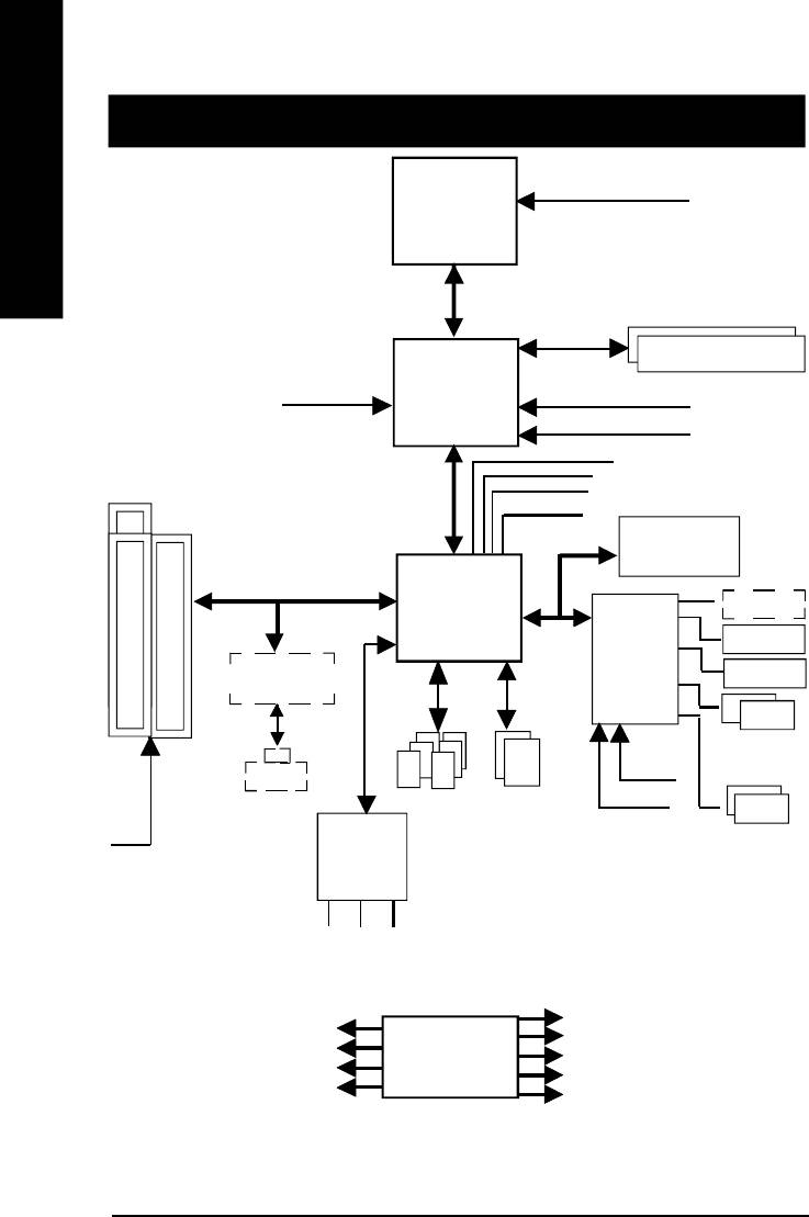
Chapter 4 Technical Reference
CPUCLK6 (100/133MHz)
Pentium 4
English
Block Diagram
CPU
System Bus 400MHz
200/266 MHz
DDR RAM
AGPCLK
Intel
(66MHz)
HCLK6 (100/133MHz)
82845GL
GMCHCLK (66MHz)
66 MHz
33 MHz
3 PCI
14.318 MHz
48 MHz
FWH
Intel
Game Port
ICH 4
LPC BUS
Floppy
ITE8712
Intel 82562ET
LPT Port
PS/2
AC97 Link
24 MHz
KB/Mouse
RJ45
ATA33/66/100
33 MHz
6 USB
IDE Channels
Ports
COM
AC97
(2.0/1.1)
PCICLK
Ports
CODEC
(33MHz)
MIC
LINE-IN
LINE-OUT
HCLK6 (100/133MHz)
PCICLK (33MHz)
CPUCLK6 (100/133MHz)
USBCLK (48MHz)
CLK
AGPCLK (66MHz)
14.318 MHz
GEN
MCHCLK (66MHz)
33 MHz
ICH3V66 (66MHz)
- 48 -GA-8ILML4 Motherboard
English
Q-Flash Introduction
A. What is Q-Flash Utility?
Q-Flash utility is a pre-O.S. BIOS flash utility enables users to update its BIOS within BIOS
mode, no more fooling around any OS.
B. How to use Q-Flash?
a. After power on the computer, pressing <Del> immediately during POST (Power On Self Test) it
will allow you to enter AWARD BIOS CMOS SETUP, then press <F8> to enter Q-Flash utility.
CMOS Setup Utility-Copyright (C) 1984-2002 Award Software
}Standard CMOS Features Load Fail-Safe Defaults
}Advanced BIOS Features Load Optimized Defaults
}Integrated Peripherals Set Supervisor Password
}Power Management Setup Set User Password
Enter Q-Flash Utility (Y/N)? Y
}PnP/PCI Configurations Save & Exit Setup
}Frequency/Voltage Control Exit Without Saving
Top Performance
ESC:Quit higf:Select Item
F8: Q-Flash F10:Save & Exit Setup
Time, Date, Hard Disk Type...
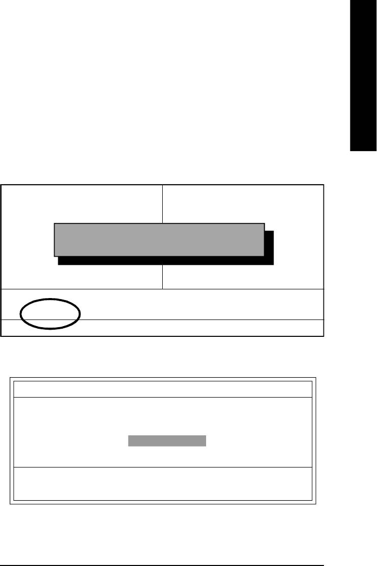
b. Q-Flash Utility
Q-Flash Utility V3.05
Flash Type/Size : SST 39SF020 / 256K
Keep DMI Data : Yes
Load BIOS from Floppy
Save BIOS to Floppy
Space Bar:Change Value
Enter: Run ESC: Reset h/i: Select Item
- 49 -
Technical Reference

Load BIOS From Floppy
!In the A:drive, insert the "BIOS" diskette, then Press Enter to Run.
1 File(s) found
English
XXXX.XX 256K
Total Size: 1.39M Free Size: 1.14M
F5: Refresh DEL: Delete ESC: Return Main
Where XXXX.XX is name of the BIOS file.
!Press Enter to Run.
Are you sure to update BIOS?
[Enter] to contiune Or [ESC] ot abort...
!Press Enter to Run.
!! COPY BIOS Completed -Pass !!
Please press any key to continue
Congratulation! You have completed the flashed and now can restart system.
- 50 -GA-8ILML4 Motherboard

English
@ BIOS Introduction
Gigabyte announces @ BIOS
Windows BIOS live update utility
Have you ever updated BIOS by yourself? Or like
many other people, you just know what BIOS is,
but always hesitate to update it? Because you think
updating newest BIOS is unnecessary and actually
you don’t know how to update it.
Maybe not like others, you are very experienced in BIOS updating and spend quite a lot of time
to do it. But of course you don’t like to do it too much. First, download different BIOS from website and
then switch the operating system to DOS mode. Secondly, use different flash utility to update BIOS.
The above process is not a interesting job. Besides, always be carefully to store the BIOS source
code correctly in your disks as if you update the wrong BIOS, it will be a nightmare.
Certainly, you wonder why motherboard vendors could not just do something right to save your
time and effort and save you from the lousy BIOS updating work? Here it comes! Now Gigabyte
announces @BIOS— the first Windows BIOS live update utility. This is a smart BIOS update
software. It could help you to download the BIOS from internetand update it. Not like the other BIOS
update software, it’s a Windows utility. With the help of “@BIOS’, BIOS updating is no more than a
click.
Besides, no matter which mainboard you are using, if it’s a Gigabyte’s product*, @BIOS help
you to maintain the BIOS. This utility could detect your correct mainboard model and help you to
choose the BIOS accordingly. It then downloads the BIOS from the nearest Gigabyte ftp site
automatically. There are several different choices; you could use “Internet Update” to download and
update your BIOS directly. Or you may want to keep a backup for your current BIOS, just choose
“Save Current BIOS” to save it first. You make a wise choice to use Gigabyte, and @BIOS update
your BIOS smartly. You are now worry free from updating wrong BIOS, and capable to maintain and
manage your BIOS easily. Again, Gigabyte’s innovative product erects a milestone in mainboard
industries.
For such a wonderful software, how much it costs? Impossible! It’s free! Now, if you buy a
Gigabyte’s motherboard, you could find this amazing software in the attached driver CD. But please
remember, connected to internet at first, then you could have a internet BIOS update from your
Gigabyte @BIOS.
- 51 -
Technical Reference

TM
Easy Tune
4 Introduction
TM
Gigabyte announces EasyTune
4
Windows based Overclocking utility
English
EasyTune 4 carries on the heritage so as to pave the way for future generations.
Overclock" might be one of the most common issues
in computer field. But have many users ever tried it?
The answer is probably "no". Because "Overclock"
is thought to be very difficult and includes a lot of
technical know-how, sometimes "Overclock" is even
considered as special skills found only in some
enthusiasts. But as to the experts in "Overclock",
what's the truth? They may spend quite a lot of time
and money to study, try and use many different hard-
ware or BIOS tools to do "Overclock". And even with these technologies, they still learn that it's quite a
risk because the safety and stability of an "Overclock" system is unknown. Now everything is different
because of a Windows based overclocking utility "EasyTune 4" --announced by Gigabyte. This win-
dows based utility has totally changed the gaming rule of "Overclock". This is the first windows based
overclocking utility is suitable for both normal and power users. Users can choose either "Easy Mode"
or "Advanced Mode" for overclocking at their convenience. For users who choose "Easy Mode", they
just need to click "Auto Optimize" to have autoed and immediate CPU overclocking. This software will
then overdrive CPU speed automatically with the result being shown in the control panel. If users prefer
"Overclock" by them, there is also another choice. Click "Advanced Mode" to enjoy "sport drive" class
Overclocking user interface. "Advanced Mode", allows users to change the system bus / AGP /
Memory working frequency in small increments to get ultimate system performance. It operates in
coordination with Gigabyte motherboards. Besides, it is different from other traditional over-clocking
methods, EasyTune 4 doesn't require users to change neither BIOS nor hardware switch/ jumper setting;
on the other hand, they can do "Overclock" at easy step . Therefore, this is a safer way for "Overclock"
as nothing is changed on software or hardware. If user runs EasyTune 4 over system's limitation, the
biggest lost is only to restart the computer again and the side effect is then well controlled. Moreover, if one
well-performed system speed has been tested in EasyTune 4, user can "Save" this setting and "Load"
it in next time. Obviously, Gigabyte EasyTune 4 has already turned the "Overclock" technology toward
to a newer generation. This wonderful software is now free bundled in Gigabyte motherboard attached in
driver CD. Users may make a test drive of "EasyTune 4" to find out more amazing features by
themselves.
*Some Gigabyte products are not fully supported by EasyTune 4. Please find the products supported list
in the web site.
*Any "Overclocking action" is at user's risk, Gigabyte Technology will not be responsible for any
damage or instability to your processor, motherboard, or any other components.
- 52 -GA-8ILML4 Motherboard
Оглавление
- Item Checklist
- Chapter 1 Introduction
- Chapter 2 Hardware Installation Process
- Chapter 5 Appendix


