Gigabyte GA-8IG1000MF-P: Chapter 2 Hardware Installation Process
Chapter 2 Hardware Installation Process: Gigabyte GA-8IG1000MF-P
English
Chapter 2 Hardware Installation Process
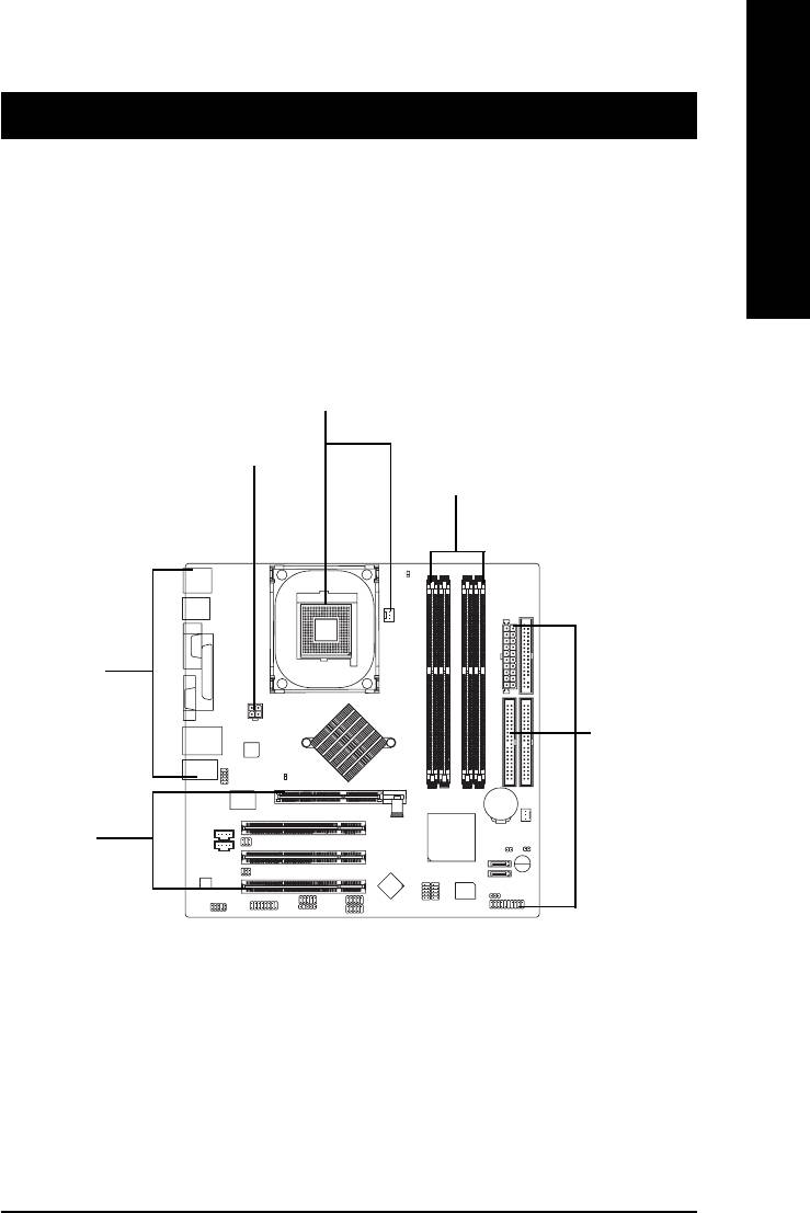
To set up your computer, you must complete the following steps:
Step 1- Install the Central Processing Unit (CPU)
Step 2- Install memory modules
Step 3- Install expansion cards
Step 4- Connect ribbon cables, cabinet wires, and power supply
Step 1
Step 4
Step 2
Step 4
Step 4
Step 3
Congratulations! You have accomplished the hardware installation!
Turn on the power supply or connect the power cable to the power outlet. Continue with the
BIOS/software installation.
- 9 - Hardware Installation Process
Step 1: Install the Central Processing Unit (CPU)
Before installing the processor, adhere to the following warning:
English
1.Please make sure the CPU type is supported by the motherboard.
2.If you do not match the CPU socket Pin 1 and CPU cut edge well, it will
cause improper installation. Please change the insert orientation.
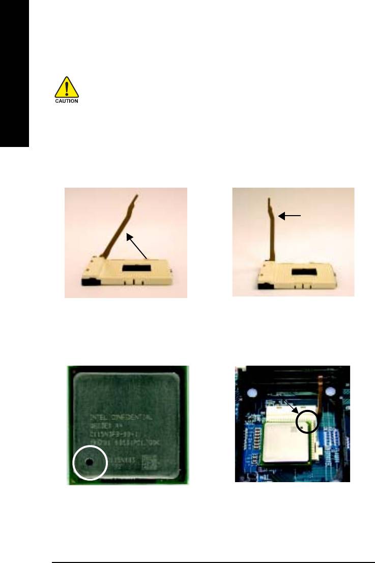
Step 1-1: CPU Installation
Socket
Angling the
Actuation
0
rod to 65
Lever
1. Angling the rod to 65-degree maybe
2. Pull the rod to the 90-degree directly.
feel a kind of tight , and then continue
pull the rod to 90-degree when a noise
"cough" made.
Pin1 indicator
Pin1 indicator
3. CPU Top View
4. Locate Pin 1 in the socket and
look for a (golden) cut edge on the
CPU upper corner. Then insert
the CPU into the socket.
- 10 -GA-8IG1000MF Series Motherboard
English
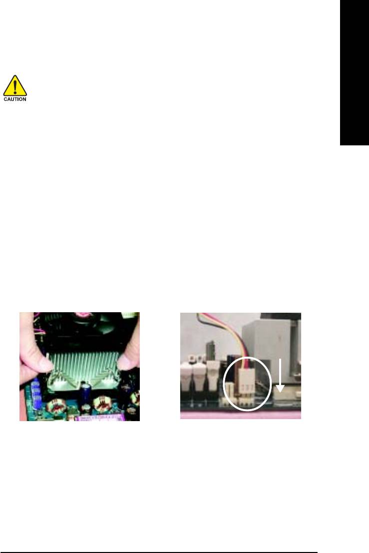
Step 1-2: CPU Cooling Fan Installation
Before installing the CPU cooling fan, adhere to the following warning:
1.Please use Intel approved cooling fan.
2.We recommend you to apply the thermal tape to provide better heat
conduction between your CPU and cooling fan.
(The CPU cooling fan might stick to the CPU due to the hardening of
the thermal paste. During this condition if you try to remove the cool-
ing fan, you might pull the processor out of the CPU socket alone with
the cooling fan, and might damage the processor. To avoid this from
happening, we suggest you to either use thermal tape instead of
thermal paste, or remove the cooling fan with extreme caution.)
3.Make sure the CPU fan power cable is plugged in to the CPU fan
connector, this completes the installation.
Please refer to CPU cooling fan user's manual for more detail
installation procedure.
1. Fasten the cooling fan supporting-
2. Make sure the CPU fan is plugged
base onto the CPU socket on the
to the CPU fan connector, than
motherboard.
install complete.
- 11 - Hardware Installation Process
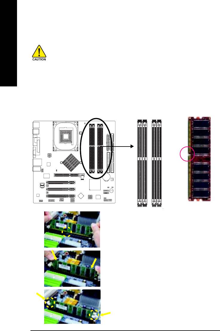
Step 2: Install Memory Modules
Before installing the memory modules, adhere to the following warning:
1.When RAM_LED is ON, do not install / remove DIMM from socket.
English
2.Please note that the DIMM module can only fit in one direction due to
the one notch. Wrong orientation will cause improper installation.
Please change the insert orientation.
The motherboard has 4 dual inline memory module (DIMM) sockets. The BIOS will automatically
detects memory type and size. To install the memory module, just push it vertically into the DIMM
socket. The DIMM module can only fit in one direction due to the notch. Memory size can vary
between sockets.
Notch
DDR
1. The DIMM socket has a notch, so the DIMM memory
module can only fit in one direction.
2. Insert the DIMM memory module vertically into the DIMM
socket. Then push it down.
3. Close the plastic clip at both edges of the DIMM sockets
to lock the DIMM module.
Reverse the installation steps when you wish to remove
the DIMM module.
- 12 -GA-8IG1000MF Series Motherboard

English
DDR Introduction
Established on the existing SDRAM industry infrastructure, DDR (Double Data Rate) memory is a
high performance and cost-effective solution that allows easy adoption for memory vendors, OEMs
and system integrators.
DDR memory is a sensible evolutionary solution for the PC industry that builds on the existing
SDRAM infrastructure, yet makes awesome advances in solving the system performance bottleneck
by doubling the memory bandwidth. DDR SDRAM will offer a superior solution and migration path from
existing SDRAM designs due to its availability, pricing and overall market support. PC2100 DDR
memory (DDR266) doubles the data rate through reading and writing at both the rising and falling edge
of the clock, achieving data bandwidth 2X greater than PC133 when running with the same DRAM
clock frequency. With peak bandwidth of 2.664GB per second, DDR memory enables system OEMs
to build high performance and low latency DRAM subsystems that are suitable for servers, workstations,
high-end PC's and value desktop SMA systems.
Dual Channel DDR:
GA-8IG1000MF Series supports Dual Channel Technology.
When Dual Channel Technology is activated, the bandwidth of memory bus will be double the original
one,with the fastest speed at 6.4GB/s DDR400.
GA-8IG1000MF Series includes four DIMM slots, and each Channel has 2 DIMMs as following:
Channel A : DIMM 1, 2
Channel B : DIMM 3, 4
Below are the explanations:
If you want to operate the Dual Channel Technology, please note the following explanations
due to the limitation of Intel chipset specifications.
1. Only one DDR memory module is installed: The Dual Channel Technology can't
operate when only one DDR memory module is installed. Additionally, you can boot the
system only when the memory module is inserted into Channel A. On the other hand,
the memory module must be inserted into DIMM1 or DIMM3 sockets.
2. Two DDR memory modules are installed (the same memory size and type): The Dual
Channel Technology will operate when two memory modules are inserted individually
into Channel A and B. If you install two memory modules in the same channel, the Dual
Channel Technology will not operate. Additionally, you can boot the system only when
one of the memory modules is inserted into Channel A. On the other hand, the memory
module must be inserted into DIMM1 or DIMM3 sockets.
3. Three DDR memory modules are installed: Please note that The Dual Channel Technol-
ogy will not operate when three DDR memory modules are installed; part of them will
not be detected.
4. Four DDR memory modules are installed: If you install four memory modules at the
same time, the Dual Channel Technology will operate only when those modules have
the same memory size and type.
- 13 - Hardware Installation Process
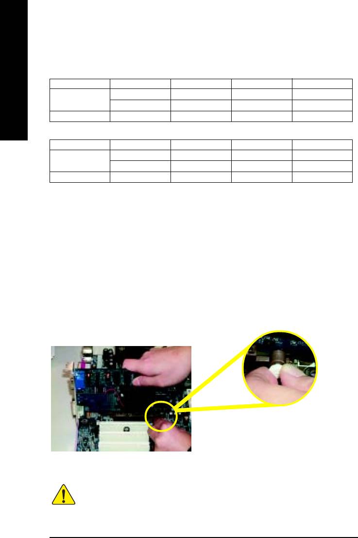
The following tables include all memory-installed combination types:
(Please note that those types not in the tables will not boot up.)
z Figure 1: Dual Channel Technology (DS: Double Side, SS: Single Side)
DIMM 1 DIMM 2 DIMM 3 DIMM 4
English
2 memory modules
DS/SS X DS/SS X
X DS/SS X DS/SS
4 memory modules
DS/SS DS/SS DS/SS DS/SS
z Figure 2: Don't operate Dual Channel Technology (DS: Double Side, SS: Single Side)
DIMM 1 DIMM 2 DIMM 3 DIMM 4
1 memory module
DS/SS X X X
X X DS/SS X
2 memory modules
DS/SS DS/SS X X
Step 3: Install expansion cards
1. Read the related expansion card's instruction document before install the expansion card into the
computer.
2. Remove your computer's chassis cover, screws and slot bracket from the computer.
3. Press the expansion card firmly into expansion slot in motherboard.
4. Be sure the metal contacts on the card are indeed seated in the slot.
5. Replace the screw to secure the slot bracket of the expansion card.
6. Replace your computer's chassis cover.
7. Power on the computer, if necessary, setup BIOS utility of expansion card from BIOS.
8. Install related driver from the operating system.
Please carefully pull out the small white-drawable
bar at the end of the AGP slot when you try to
install/ Uninstall the AGP card. Please align the
AGP card to the onboard AGP slot and press firmly
down on the slot .Make sure your AGP card is
AGP Card
locked by the small white- drawable bar.
When an AGP 2X (3.3V) card is installed the 2X_DET will light up, indicating a non-supported
graphics card is inserted. Informing users that system might not boot up normally due to
AGP 2X (3.3V) is not supported by the chipset.
- 14 -GA-8IG1000MF Series Motherboard
English
Step 4: Connect ribbon cables, cabinet wires and power supply
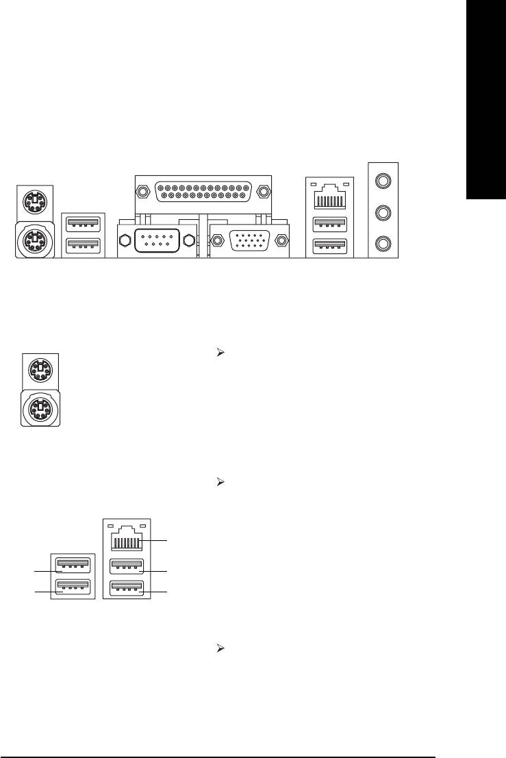
Step 4-1: I/O Back Panel Introduction
\
Z
[
X
Y
X PS/2 Keyboard and PS/2 Mouse Connector
XX
XX
This connector supports standard PS/2
PS/2 Mouse Connector
keyboard and PS/2 mouse.
(6 pin Female)
PS/2 Keyboard Connector
(6 pin Female)
Y/[ USB/LAN Connector
Before you connect your device(s) into USB
connector(s), please make sure your device(s)
such as USB keyboard, mouse, scanner, zip,
speaker...etc. have a standard USB interface.
LAN
Also make sure your OS supports USB controller.
USB 0
USB 2
If your OS does not support USB controller, please
USB 1
USB 3
contact OS vendor for possible patch or driver
upgrade. For more information please contact your
OS or device(s) vendors.
LAN connector for GA-8IG1000MF-P is Gigabit
Ethernet with 10/100/1000Mbps speed.
LAN connector for GA-8IG1000MF is fast
Ethernet with 10/100Mbps speed.
- 15 - Hardware Installation Process
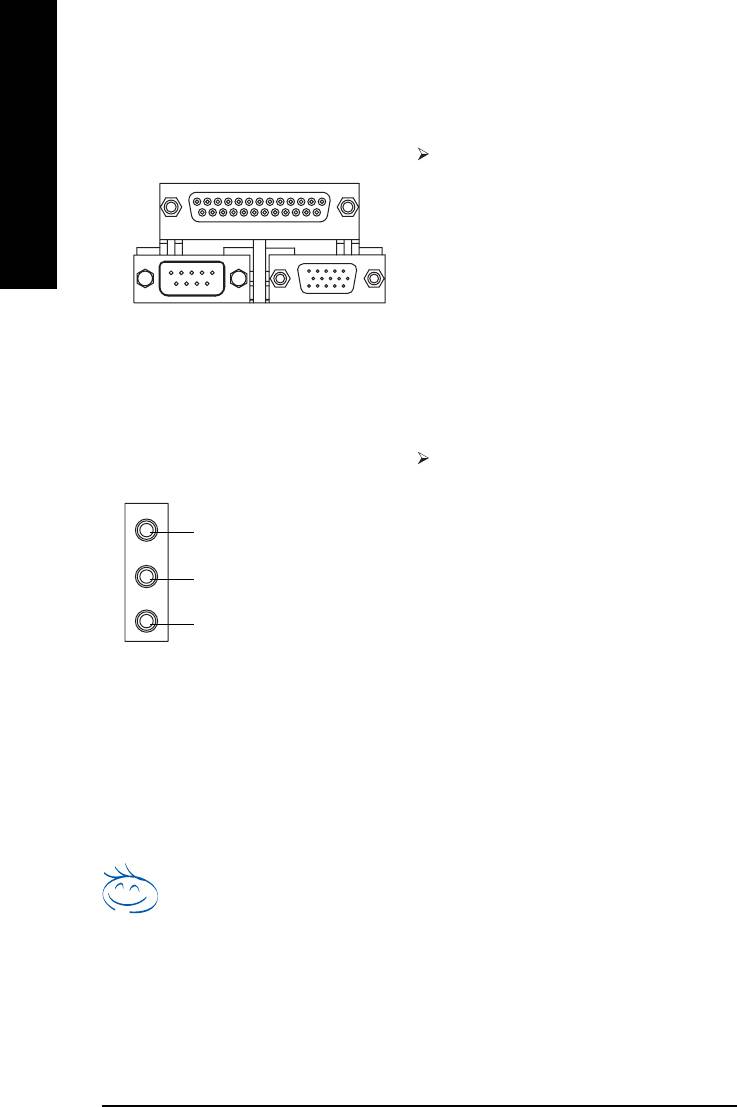
Z Parallel Port, Serial Port and VGA port (LPT / COMA / VGA)
Parallel Port
This connector supports 1 standard COM port ,
(25 pin Female)
1 Parallel port and 1 VGA port. Device like printer
English
can be connected to Parallel port; mouse and
modem etc. can be connected to Serial ports.
COMA VGA
Serial Port
VGA Port
(9 pin Male)
(15 pin Female)
\ Audio Connectors
After install onboard audio driver, you may
connect speaker to Line Out jack, microphone to
MIC In jack. Device like CD-ROM,walkman
Line In (Rear Speaker)
etc. can be connected to Line-In jack.
Please note:
Line Out (Front Speaker)
You are able to use 2-/4-/6-channel audio feature
by S/W selection.
MIC In (Center and Subwoofer)
If you want to enable 6-channel function, you
have 2 choose for hardware connection.
Method1:
Connect "Front Speaker" to "Line Out"
Connect "Rear Speaker" to "Line In"
Connect "Center and Subwoofer" to "MIC Out ".
Method2:
You can refer to page 26, and contact your
nearest dealer for optional SUR_CEN cable.
If you want the detail information for 2-/4-/6-channel audio setup
installation, please refer to page 74.
- 16 -GA-8IG1000MF Series Motherboard
English
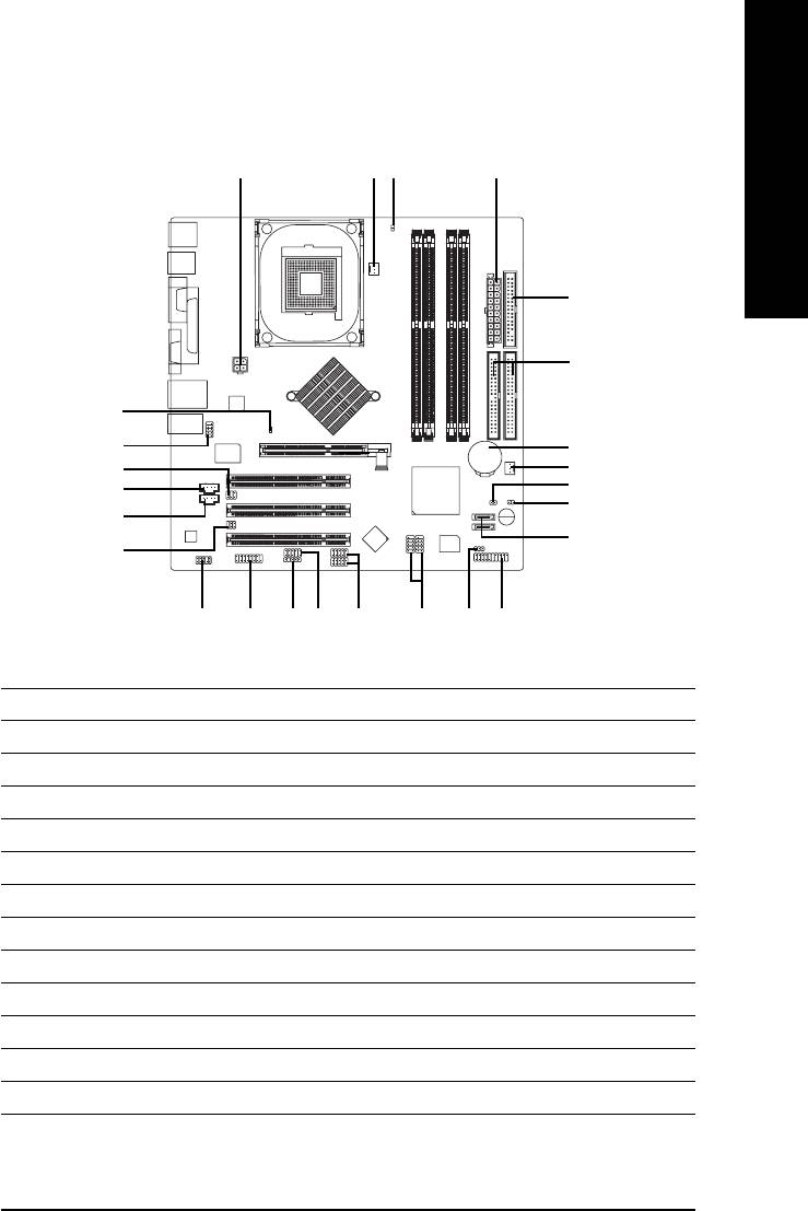
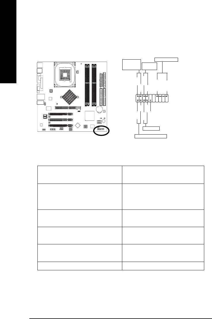
Step 4-2: Connectors Introduction
13
11
2
5
6
12
20
8
16
4
14
24*
#
25
#
15
7
17*
22
21
23
19
18
1013
9
1) ATX_12V
14) CD_IN
#
2) ATX
15) AUX_IN
3) CPU_FAN
16) SUR_CEN
4) SYS_FAN
17) SPDIF_IO*
5) FDD
18) F_USB1 / F_USB2
6) IDE1 / IDE2
19) F1_1394 / F2_1394
7) SATA0 / SATA1
20) COMB
8) BAT
21) IR
9) F_PANEL
22) GAME
10) PWR_LED
23) INFO_LINK
11) RAM_LED
24) CLR_CMOS*
#
12) 2X_DET
25) CI
13) F_AUDIO
* For GA-8IG1000MF-P only.
#
For GA-8IG1000MF only.
- 17 - Hardware Installation Process
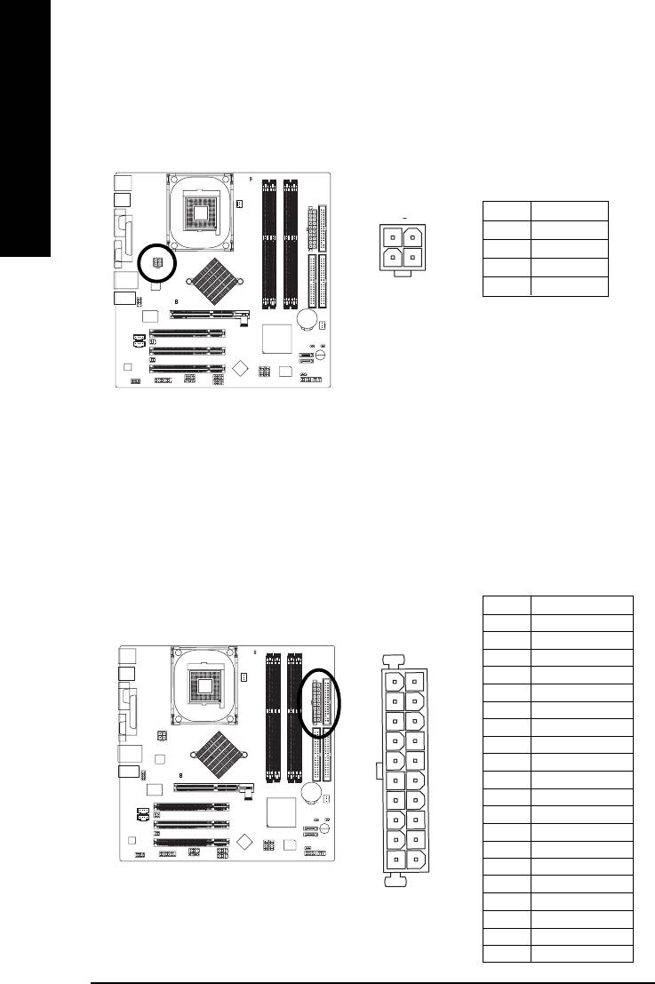
1) ATX_12V (+12V Power Connector)
This connector (ATX_12V) supplies the CPU operation voltage (Vcore).
If this "ATX_12V connector" is not connected, system cannot boot.
English
2) ATX (ATX Power)
AC power cord should only be connected to your power supply unit after ATX power cable and
other related devices are firmly connected to the mainboard.
Pin No. Definition
1 3.3V
2 3.3V
3 GND
4 VCC
5 GND
6 VCC
7 GND
8 Power Good
9 5V SB (stand by +5V)
10 +12V
11 3.3V
12 -12V
13 GND
14 PS_ON(soft on/off)
15 GND
16 GND
17 GND
18 -5V
19 VCC
20 VCC
- 18 -GA-8IG1000MF Series Motherboard
_
Pin No. Definition
1 GND
2
1
2 GND
4
3
3 +12V
4 +12V
11
1
20
10
English
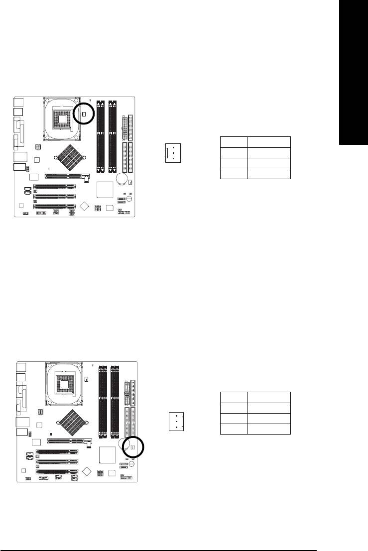
3) CPU_FAN (CPU Fan Connector)
Please note, a proper installation of the CPU cooler is essential to prevent the CPU from running
under abnormal condition or damaged by overheating. The CPU fan connector supports Max.
current up to 600 mA.
1
Pin No. Definition
1 GND
2 +12V
3 Sense
4) SYS_FAN (System Fan Connector)
This connector allows you to link with the cooling fan on the system case to lower the system
temperature.
Pin No. Definition
1 GND
2 +12V
3 Sense
1
- 19 - Hardware Installation Process
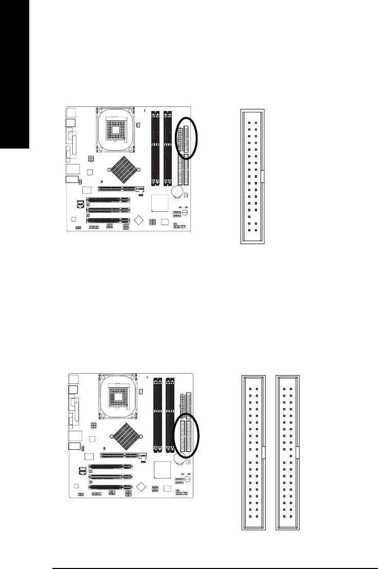
5) FDD (Floppy Connector)
Please connect the floppy drive ribbon cables to FDD. It supports 360K, 1.2M, 720K, 1.44M and
2.88M bytes floppy disk types.
The red stripe of the ribbon cable must be the same side with the Pin1.
English
34
33
2
1
6) IDE1 / IDE2 (IDE1 / IDE2 Connector)
Important Notice:
Please connect first hard disk to IDE1 and connect CD-ROM to IDE2.
The red stripe of the ribbon cable must be the same side with the Pin1.
3940
12
IDE2
IDE1
- 20 -GA-8IG1000MF Series Motherboard
English
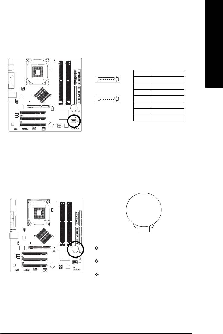
7) SATA0 / SATA1 (Serial ATA Connector)
You can connect the Serial ATA device to this connector, it provides you high speed transfer rates
(150MB/sec).
Pin No. Definition
7
1
1 GND
2 TXP
SATA1
3 TXN
4 GND
17
5 RXN
SATA0
6 RXP
7 GND
8) BAT (BATTERY)
+
CAUTION
Danger of explosion if battery is incorrectly
replaced.
Replace only with the same or equivalent type
recommended by the manufacturer.
Dispose of used batteries according to the
manufacturer's instructions.
If you want to erase CMOS...
1. Turn OFF the computer and unplug the power cord.
2. Remove the battery, wait for 30 second.
3. Re-install the battery.
4. Plug the power cord and turn ON the computer.
- 21 - Hardware Installation Process
9) F_PANEL (2 x 10 pins Connector)
Please connect the power LED, PC speaker, reset switch and power switch etc of your chassisfront
panel to the F_PANEL connector according to the pin assignment above.
English
Speaker Connector
Message LED/
Power/
Soft Power
Sleep LED
Connector
PW+
MSG+
MSG-
PW-
SPEAK+
SPEAK-
2
11
1
20
1
1
1
19
HD-
RES+
NC
HD+
RES-
Reset Switch
IDE Hard Disk Active LED
HD (IDE Hard Disk Active LED) Pin 1: LED anode(+)
Pin 2: LED cathode(-)
SPK (Speaker Connector) Pin 1: VCC(+)
Pin 2- Pin 3: NC
Pin 4: Data(-)
RES (Reset Switch) Open: Normal Operation
Close: Reset Hardware System
PW (Soft Power Connector) Open: Normal Operation
Close: Power On/Off
MSG (Message LED/ Power/ Sleep LED) Pin 1: LED anode(+)
Pin 2: LED cathode(-)
NC (Purple) NC
- 22 -GA-8IG1000MF Series Motherboard
English
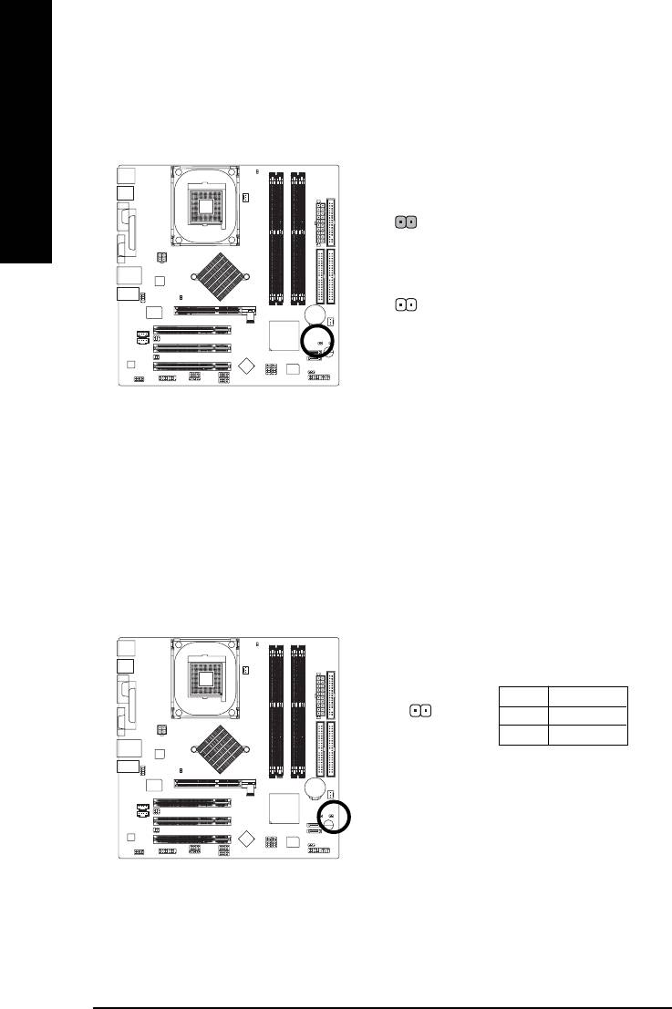
10) PWR_LED
PWR_LED is connect with the system power indicator to indicate whether the system is on/off.
It will blink when the system enters suspend mode. If you use dual color LED, power LED will turn
to another color.
1
Pin No. Definition
1 MPD+
2 MPD-
3 MPD-
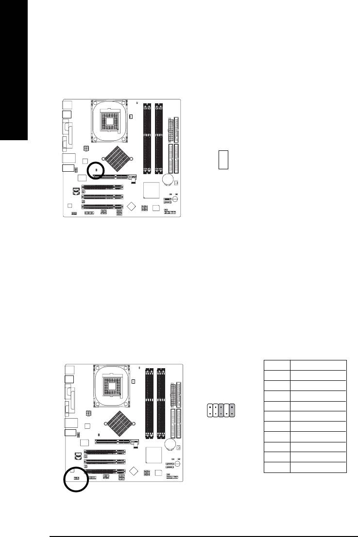
11) RAM_LED
Do not remove memory modules while RAM_LED is on. It might cause short or other unexpected
damages due to the stand by voltage. Remove memory modules only when AC power cord is
disconnected.
_
+
- 23 - Hardware Installation Process
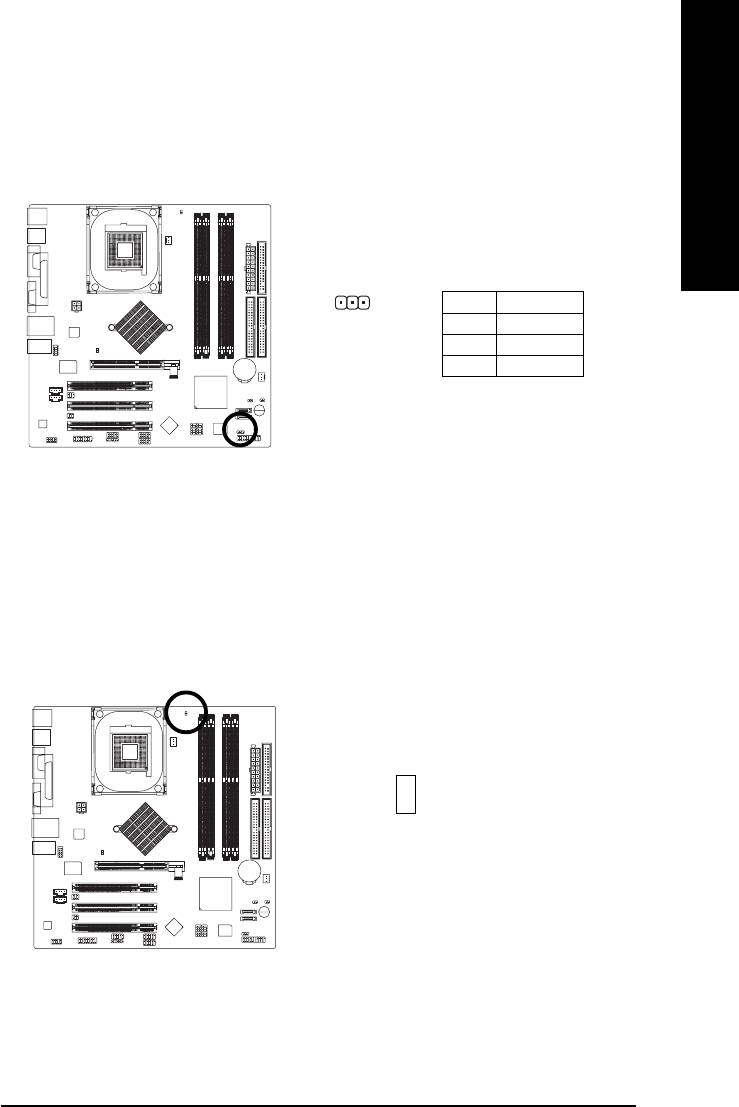
12) 2X_DET
When an AGP 2X (3.3V) card is installed the 2X_DET will light up, indicating a non-supported
graphics card is inserted. Informing users that system might not boot up normally due to AGP 2X
(3.3V) is not supported by the chipset.
English
_
+
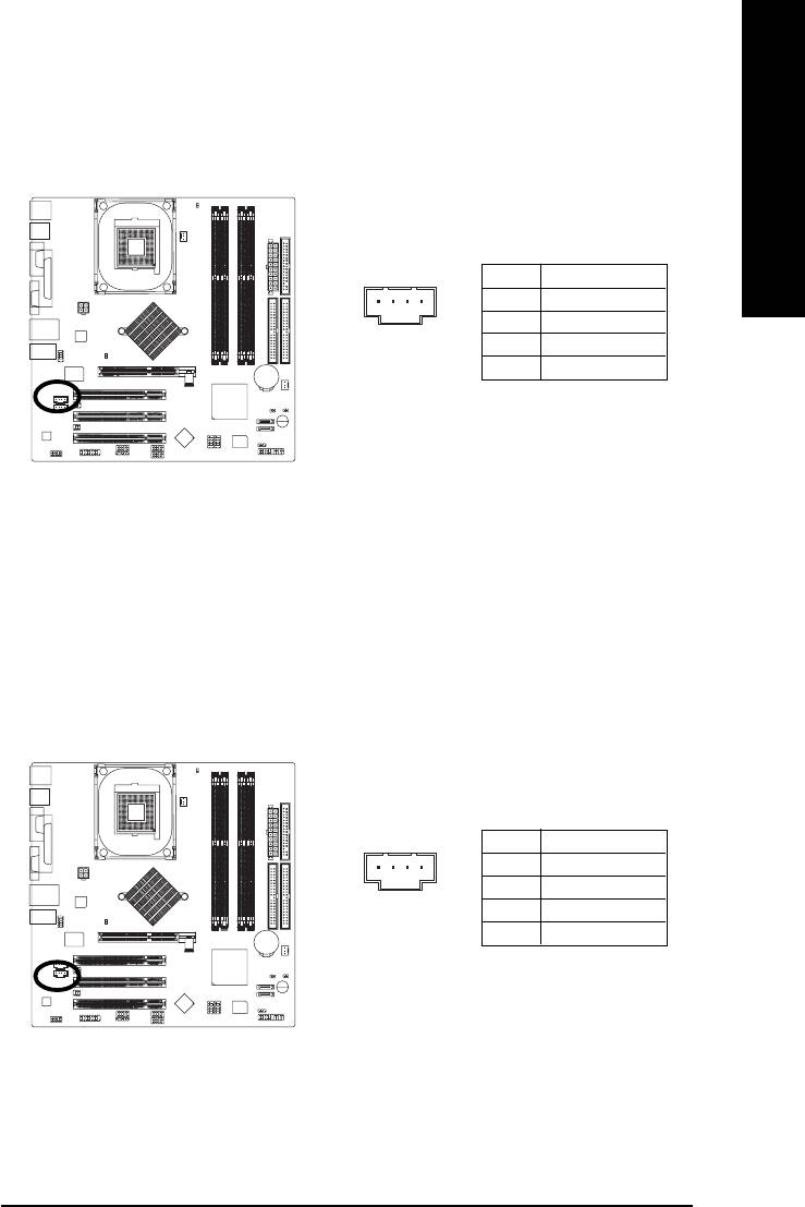
13) F_AUDIO (Front Audio Connector)
If you want to use Front Audio connector, you must remove 5-6, 9-10 Jumper.
In order to utilize the front audio header, your chassis must have front audio connector. Also please
make sure the pin assigment on the cable is the same as the pin assigment on the MB header. To
find out if the chassis you are buying support front audio connector, please contact your dealer.
Please note, you can have the alternative of using front audio connector or of using rear audio
connector to play sound.
Pin No. Definition
1 MIC
2 GND
3 REF
2
10
4 Power
5 Front Audio (R)
1
9
6 Rear Audio (R)
7 Reserved
8 No Pin
9 Front Audio (L)
10 Rear Audio (L)
- 24 -GA-8IG1000MF Series Motherboard
English
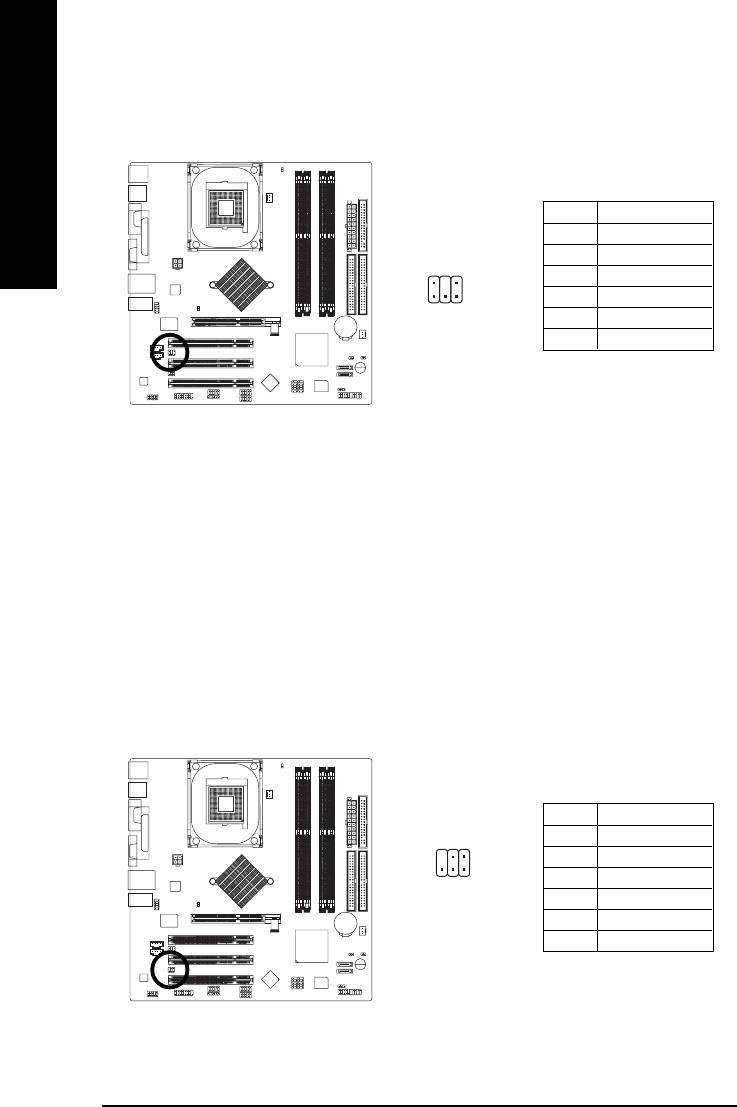
14)CD_IN (CD In Connector)
Connect CD-ROM or DVD-ROM audio out to the connector.
Pin No. Definition
1 CD-L
1
2 GND
3 GND
4 CD-R
#
15) AUX_IN (AUX In Connector)
Connect other device (such as PCI TV Tunner audio out) to the connector.
Pin No. Definition
1 AUX-L
1
2 GND
3 GND
4 AUX-R
* For GA-8IG1000MF-P only.
#
For GA-8IG1000MF only.
- 25 - Hardware Installation Process
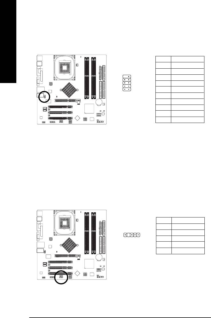
16)SUR_CEN (Surround Center Connector)
Please contact your nearest dealer for optional SUR_CEN cable.
English
Pin No. Definition
1 SUR OUTL
2 SUR OUTR
2
6
3 GND
4 No Pin
1
5
5 CENTER_OUT
6 BASS_OUT
17)SPDIF_IO (SPDIF In / Out Connector)*
The SPDIF output is capable of providing digital audio to external speakers or compressed AC3
data to an external Dolby Digital Decoder. Use this feature only when your stereo system has
digital input function. Be careful with the polarity of the SPDIF_IO connector. Check the pin
assignment carefully while you connect the SPDIF_IO cable, incorrect connection between the
cable and connector will make the device unable to work or even damage it. For optional
SPDIF_IO cable, please contact your local dealer.
Pin No. Definition
1 VCC
2
6
2 No Pin
1
5
3 SPDIF
4 SPDIFI
5 GND
6 GND
* For GA-8IG1000MF-P only.
#
For GA-8IG1000MF only.
- 26 -GA-8IG1000MF Series Motherboard
English
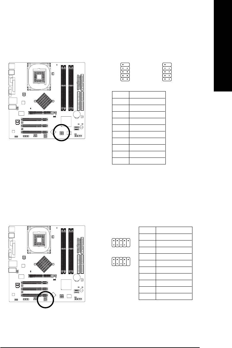
18)F_USB1 / F_USB2 (Front USB Connector, Yellow)
Be careful with the polarity of the front USB connector. Check the pin assignment while you
connect the front USB cable. Please contact your nearest dealer for optional front USB cable.
10
9
10
9
F_USB1
F_USB2
2
1
2
1
Pin No. Definition
1 Power
2 Power
3 USB Dx-
4 USB Dy-
5 USB Dx+
6 USB Dy+
7 GND
8 GND
9 No Pin
10 NC
19) F1_1394 / F2_1394 (IEEE1394 Connector)
Please Note: Serial interface standard set by Institute of Electrical and Electronics Engineers,
which has features like high speed, highbandwidth and hot plug.
Pin No. Definition
1 TPA2+
2
10
F1_1394
2 TPA2-
1
9
3 GND
4 GND
2
10
F2_1394
1
9
5 TPB2+
6 TPB2-
7 Power
8 Power
9 No Pin
10 GND
- 27 - Hardware Installation Process
20) COMB (COM B Connector)
Be careful with the polarity of the COMB connector. Check the pin assignment while you connect
the COMB cable. Please contact your nearest dealer for optional COMB cable.
English
Pin No. Definition
1 NDCDB-
10
9
2 NSINB
3 NSOUTB
4 NDTRB-
5 GND
2
1
6 NDSRB-
7 NRTSB-
8 NCTSB-
9 NRIB-
10 No Pin
21) IR
Make sure the pin 1 on the IR device is aling with pin one the connector. To enable the IR function
on the board, you are required to purchase an option IR module. For detail information please
contact your autherized Gigabyte distributor.
Pin No. Definition
1 VCC(+5V)
2 No Pin
15
3 IR Data Input
4 GND
5 IR Data Output
- 28 -GA-8IG1000MF Series Motherboard
English
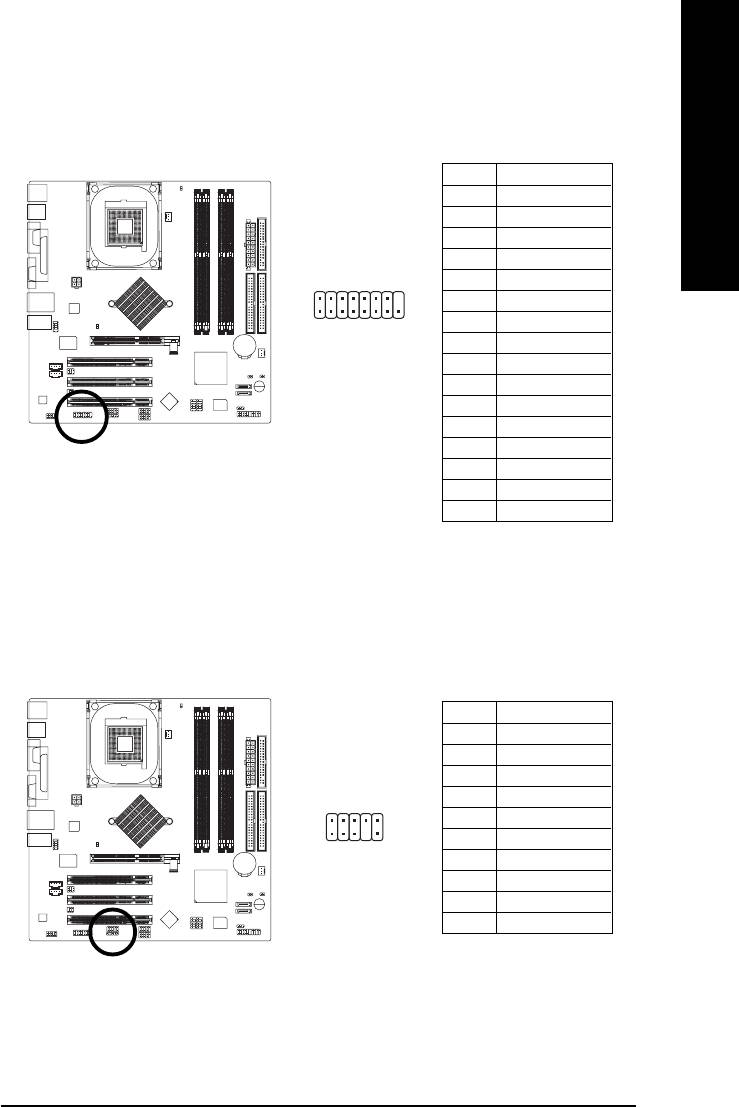
22) GAME (Game Connector)
This connector supports joystick, MIDI keyboard and other relate audio devices.
Pin No. Definition
1 VCC
2 GRX1_R
3 GND
4 GPSA2
2
16
5 VCC
6 GPX2_R
7 GPY2_R
1
15
8 MSI_R
9 GPSA1
10 GND
11 GPY1_R
12 VCC
13 GPSB1
14 MSO_R
15 GPSB2
16 No Pin
23) INFO_LINK
This connector allows you to connect some external devices to provide you extra function.
Pin No. Definition
1 SMBCLK
2 VCC
3 SMBDATA
102
4 GPIO
5 GND
6 GND
1
9
7 No Pin
8NC
9 +12V
10 +12V
- 29 - Hardware Installation Process
24) CLR_CMOS (Clear CMOS)*
You may clear the CMOS data to its default values by this jumper. To clear CMOS, temporarily
shor 1-2 pin. Default doesn't include the "Shunter" to prevent from improper use this jumper.
English
1 1-2 close: Clear CMOS
1
Open: Normal
#
25)CI (Chassis Intrusion, Case Open)
This 2-pin connector allows your system to enable or disable the "Case Open" item in BIOS, if the
system case begin remove.
Pin No. Definition
1
1 Signal
2 GND
* For GA-8IG1000MF-P only.
#
For GA-8IG1000MF only.
- 30 -GA-8IG1000MF Series Motherboard


