Gigabyte GA-78LMT-S2P: Chapter 3 Drivers Installation
Chapter 3 Drivers Installation: Gigabyte GA-78LMT-S2P
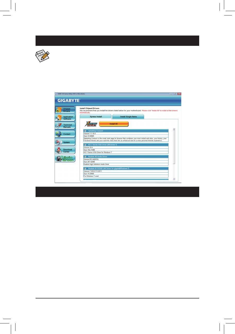
Chapter 3 Drivers Installation
• Before installing the drivers, rst install the operating system.
• After installing the operating system, insert the motherboard driver disk into your optical drive.
The driver Autorun screen is automatically displayed which looks like that shown in the screen
shot below. (If the driver Autorun screen does not appear automatically, go to My Computer,
double-click the optical drive and execute the Run.exe program.)
After inserting the driver disk, "Xpress Install" will automatically scan your system and then list all the drivers
that are recommended to install. You can click the Install All button and "Xpress Install" will install all the rec-
ommended drivers. Or click Install Single Items to manually select the drivers you wish to install.
Chapter 4 Appendix
ConguringSATAHardDrive(s)
Before you begin
Please prepare:
• At least two SATA hard drives (to ensure optimal performance, it is recommended that you use two hard
drives with identical model and capacity). If you do not want to create RAID, you may prepare only one
hard drive.
• An empty formatted oppy disk.
• Windows Vista/XP setup disk.
• Motherboard driver disk.
ConguringtheOnboardSATAController
A. Installing SATA hard drive(s) in your computer
Attach one end of the SATA signal cable to the rear of the SATA hard drive and the other end to available
SATA port on the motherboard. Then connect the power connector from your power supply to the hard drive.
B.ConguringSATAcontrollermodeinBIOSSetup
Make sure to configure the SATA controller mode correctly in system BIOS Setup. For the BIOS Setup
menus, refer to Chapter 2, "BIOS Setup," "Integrated Peripherals."
- 37 - BIOS Setup

Steps:
1. Turn on your computer and press <Delete> to enter BIOS Setup during the POST (Power-On Self-Test).
Ensure OnChip SATA Controller is enabled under Integrated Peripherals. To enable RAID for the
SATA2_0/1/2/3 connectors, set OnChip SATA Type to RAID. To enable RAID for the SATA2_4/5 connec-
tors, set OnChip SATA Type to RAID and set OnChip SATA Port4/5 Type to As SATA Type.
2. Save changes and exit BIOS Setup.
The BIOS Setup menus described in this section may differ from the exact settings for your moth-
erboard. The actual BIOS Setup menu options you will see shall depend on the motherboard you
have and the BIOS version.
C.ConguringRAIDsetinRAIDBIOS
Enter the RAID BIOS setup utility to congure a RAID array. After the POST memory test begins and
before the operating system boot begins, look for a message which says "Press <Ctrl-F> to enter RAID
Option ROM Utility". Press <Ctrl> + <F> to enter the RAID BIOS setup utility. To create a new array, press
<2> to enter the LDView/LDDeneMenu window. To create an array, press <Ctrl+C> to access the LD
DeneMenu. In the LDDeneMenu, use the up or down arrow key to move to an item for further congu-
ration. In the following procedure, we'll create RAID 0 as an example.
Steps:
1. Under the RAID Mode section, press the <SPACE> key to select RAID 0.
2. Set the Stripe Block size. 64 KB is the default.
3. Under the Drives Assignments section, press the up or down arrow key to highlight a drive.
4. Press the <SPACE> key or <Y>to change the Assignment option to Y. This action adds the drive to the
disk array. The Drv section will show the number of disks assigned.
5. Press <Ctrl>+<Y> keys to save the information. The message in Figure 1 will appear. Press <Ctrl>+<Y>
to input the array name. If you do not input the array name, the default array name will be used.
Please press Ctrl-Y key to input the LD Name
or press any key to exit.
If you do not input any LD name, the default
LDnamewillbeused.
Figure 1
6. When the next message appears, press <Ctrl>+<Y> to clear the MBR or press other keys to ignore this
option.
FastInitializationOptionhasbeenselected
It will erase the MBR data of the disk.
<PressCtrl-YKeyifyouaresuretoeraseit>
<Pressanyotherkeytoignorethisoption>
Figure 2
7. Then, the message in Figure 8 will appear. Press <Ctrl>+<Y> to set the capacity of the RAID array or
press other keys to set the array to its maximum capacity.
Press Ctrl-Y to Modify Array Capacity or press any
other key to use maximum capacity...
Figure 3
8. After the creation is complete, the screen will return to LD View Menu where you will see the newly-
created array.
9. Press <Esc> to return to Main Menu and press <Esc> again if you want to exit the RAID BIOS utility.
Appendix - 38 -

Making a SATA RAID Driver Diskette
Copy the driver for the SATA controller from the motherboard driver disk to a oppy disk (for Windows XP) or
a USB ash drive (for Windows 7/Vista). For example, to copy the RAID driver for Windows XP 32-bit operat-
ing system, copy the driver from the following directory to your oppy disk: \BootDrv\SBxxx\x86. (To install
Windows 64-bit, copy the les in the x64 folder.)
Installing the SATA RAID Driver and Operating System
A. Installing Windows XP
Before installing Windows XP, connect a USB oppy disk drive to your computer. Restart your system to boot
from the Windows XP setup disk and press <F6> as soon as you see the message "Press F6 if you need to
install a 3rd party SCSI or RAID driver." Insert the oppy disk containing the SATA controller driver. Follow
the on-screen instructions to install the two drivers displayed. When completed, proceed with the Windows
XP installation.
B. Installing Windows 7/Vista
Restart your system to boot from the Windows 7/Vista setup disk and perform standard OS installation steps.
Select Load Driver. Insert the oppy disk/USB ash drive (for users using a SATA optical drive) containing the
driver or insert the motherboard driver disk. For Windows 32-bit, browse to \BootDrv\SBxxxW7\RAID\W7 to
load the driver and continue the OS installation. For Windows 64-bit, browse to \BootDrv\SBxxxW7\RAID\
W764A to load the driver and continue the OS installation.
- 39 - Appendix

Appendix - 40 -
- 41 - Appendix

Appendix - 42 -

- 43 - Appendix
Contact Us
GIGA-BYTE TECHNOLOGY CO., LTD.
Address: No.6, Bao Chiang Road, Hsin-Tien Dist., New Taipei City 231,Taiwan
TEL: +886-2-8912-4000, FAX: +886-2-8912-4003
Tech. and Non-Tech. Support (Sales/Marketing) : http://ggts.gigabyte.com.tw
WEB address (English): http://www.gigabyte.com
WEB address (Chinese): http://www.gigabyte.tw
You may go to the GIGABYTE website, select your language in the language list on the top right corner of the website.
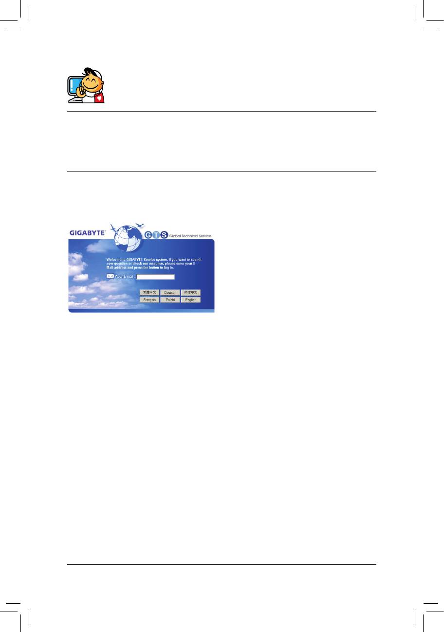
• GIGABYTE Global Service System
To submit a technical or non-technical (Sales/Market-
ing) question, please link to:
http://ggts.gigabyte.com.tw
Then select your language to enter the system.
Appendix - 44 -


