Gigabyte GA-78LMT-S2P: Chapter 2 BIOS Setup
Chapter 2 BIOS Setup: Gigabyte GA-78LMT-S2P

Chapter 2 BIOS Setup
To access the BIOS Setup program, press the <Delete> key during the POST when the power is turned on.
To see more advanced BIOS Setup menu options, you can press <Ctrl> + <F1> in the main menu of the
BIOS Setup program.
To upgrade the BIOS, use either the GIGABYTE Q-Flash or @BIOS utility.
Q-Flash allows the user to quickly and easily upgrade or back up BIOS without entering the operating •
system.
@BIOS is a Windows-based utility that searches and downloads the latest version of BIOS from the •
Internet and updates the BIOS.
Because BIOS ashing is potentially risky, if you do not encounter problems using the current •
version of BIOS, it is recommended that you not ash the BIOS. To ash the BIOS, do it with
caution. Inadequate BIOS ashing may result in system malfunction.
It is recommended that you not alter the default settings (unless you need to) to prevent system •
instability or other unexpected results. Inadequately altering the settings may result in system's
failure to boot. If this occurs, try to clear the CMOS values and reset the board to default values.
(Refer to the "Load Optimized Defaults" section in this chapter or introductions of the battery/
clearing CMOS jumper in Chapter 1 for how to clear the CMOS values.)
2-1 Startup Screen
The following screens may appear when the computer boots.
A. The LOGO Screen (Default): GA-78LMT-USB3
Function Keys
B. The POST Screen
Award Modular BIOS v6.00PG
Copyright (C) 1984-2011, Award Software, Inc.
GA-78LMT-USB3 D13
.
Motherboard Model
.
BIOS Version
.
.
<DEL>: BIOS Setup <F9>: XpressRecovery2 <F12>: Boot Menu <End>: Qflash
Function Keys
03/15/2011-RS780L-SB710-7A66CG0HC-00
BIOS Setup - 20 -

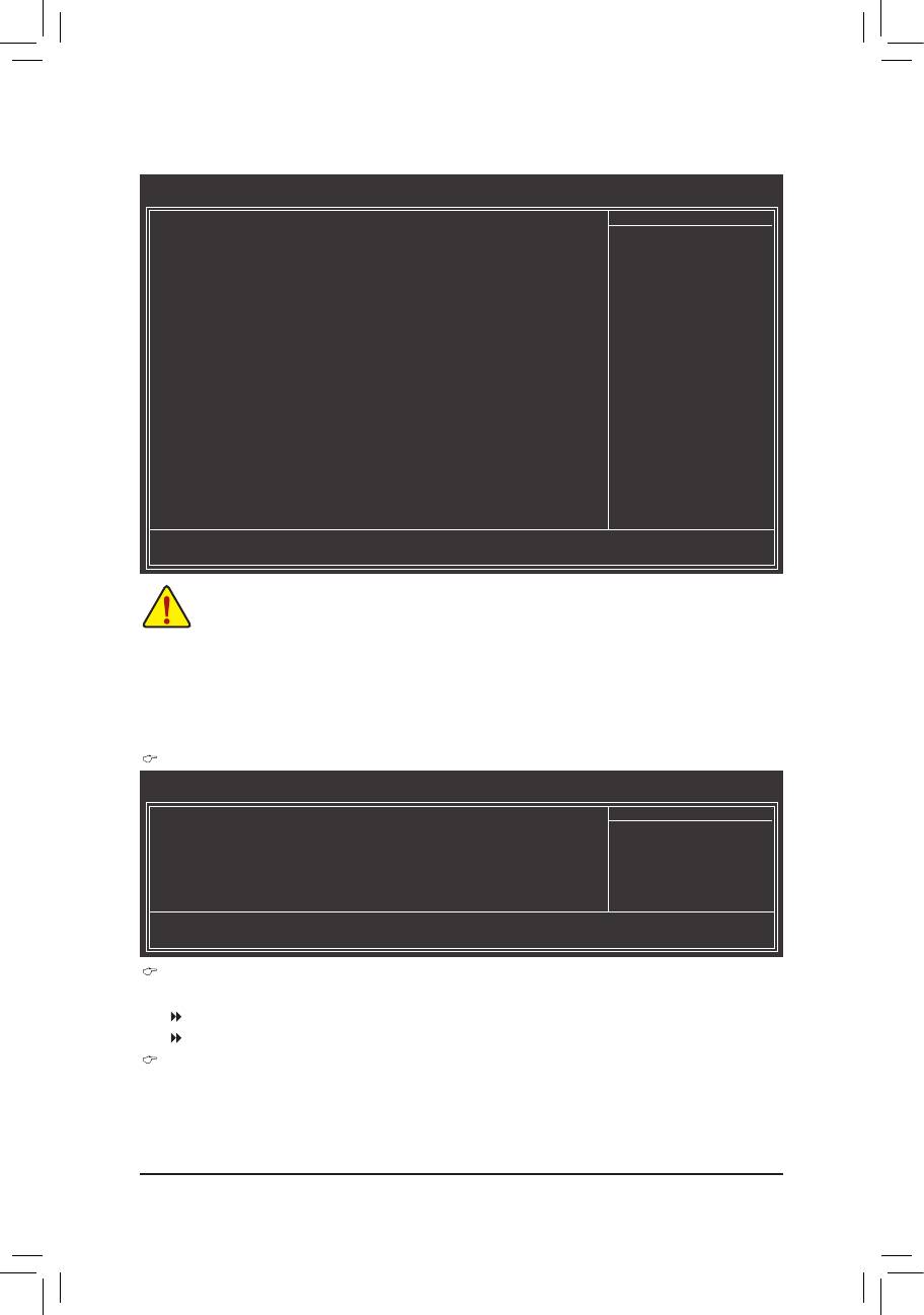
2-2 The Main Menu
Once you enter the BIOS Setup program, the Main Menu (as shown below) appears on the screen. Use ar-
row keys to move among the items and press <Enter> to accept or enter a sub-menu.
(Sample BIOS Version: GA-78LMT-USB3 D13)
CMOS Setup Utility-Copyright (C) 1984-2011 Award Software
MB Intelligent Tweaker(M.I.T.)
Load Fail-Safe Defaults
Standard CMOS Features
Load Optimized Defaults
Advanced BIOS Features
Set Supervisor Password
Integrated Peripherals
Set User Password
Power Management Setup
Save & Exit Setup
PnP/PCICongurations
Exit Without Saving
PC Health Status
ESC: Quit
: Select Item F11: Save CMOS to BIOS
F8: Q-Flash F10: Save & Exit Setup F12: Load CMOS from BIOS
Change CPU's Clock & Voltage
If you do not nd the settings you want in the Main Menu or a submenu, press <Ctrl>+<F1> to •
access more advanced options.
When the system is not stable as usual, select the • Load Optimized Defaults item to set your
system to its defaults.
The BIOS Setup menus described in this chapter are for reference only and may differ by BIOS •
version.
The Functions of the <F11> and <F12> keys (For the Main Menu Only)
F11: Save CMOS to BIOS
This function allows you to save the current BIOS settings to a prole. You can create up to 8 proles
(Prole 1-8) and name each prole. First enter the prole name (to erase the default prole name, use
the SPACE key) and then press <Enter> to complete.
F12: Load CMOS from BIOS
If your system becomes unstable and you have loaded the BIOS default settings, you can use this
function to load the BIOS settings from a prole created before, without the hassles of reconguring the
BIOS settings. First select the prole you wish to load, then press <Enter> to complete.
- 21 - BIOS Setup
2-3 MB Intelligent Tweaker(M.I.T.)
CMOS Setup Utility-Copyright (C) 1984-2011 Award Software
MB Intelligent Tweaker(M.I.T.)
IGXConguration [PressEnter]
Item Help
CPUClockRatio [Auto] 2800Mhz
Menu Level
CPU NorthBridge Freq.
[Auto] 2000Mhz
(Note)
Core Performance Boost
[Enabled]
(Note)
CPB Ratio
[Auto] 3100Mhz
(Note)
TurboCPB
[Disabled]
CPUHostClockControl [Auto]
x CPU Frequency(MHz) 200
PCIEClock(MHz) [Auto]
HTLinkWidth [Auto]
HTLinkFrequency [Auto] 2000Mhz
SetMemoryClock [Auto]
x Memory Clock x4.00 800Mhz
DRAMConguration [PressEnter]
********
System Voltage Optimized
********
SystemVoltageControl [Auto]
x DDR3 Voltage control Auto
x NorthBridge Volt Control Auto
x SouthBridge Volt Control Auto
x CPU NB VID Control Auto
x CPU Voltage Control Auto
Normal CPU Vcore 1.2750V
: Move Enter: Select +/-/PU/PD: Value F10: Save ESC: Exit F1: General Help
F5: Previous Values F6: Fail-Safe Defaults F7: Optimized Defaults
• Whether the system will work stably with the overclock/overvoltage settings you made is depen-
dent on your overall system congurations. Incorrectly doing overclock/overvoltage may result in
damage to CPU, chipset, or memory and reduce the useful life of these components. This page is
for advanced users only and we recommend you not to alter the default settings to prevent system
instability or other unexpected results. (Inadequately altering the settings may result in system's
failure to boot. If this occurs, clear the CMOS values and reset the board to default values.)
• When the System Voltage Optimized item blinks in red, it is recommended that you set the
System Voltage Control item to Auto to optimize the system voltage settings.
IGXConguration
CMOS Setup Utility-Copyright (C) 1984-2011 Award Software
IGXConguration
InternalGraphicsMode [UMA]
Item Help
UMAFrameBufferSize [Auto]
Menu Level
x SurroundView Disabled
VGACoreClockcontrol [Auto]
x VGA Core Clock(MHz) 350
: Move Enter: Select +/-/PU/PD: Value F10: Save ESC: Exit F1: General Help
F5: Previous Values F6: Fail-Safe Defaults F7: Optimized Defaults
Internal Graphics Mode
Allows you to determine whether to allocate system memory for the onboard graphics controller.
Disabled Disables the onboard graphics controller.
UMA Allocates memory for the onboard graphics controller from the system memory. (Default)
UMA Frame Buffer Size
Frame buffer size is the total amount of system memory allocated solely for the onboard graphics con-
troller. MS-DOS, for example, will use only this memory for display. Options are: Auto (default), 128MB,
256MB, 512MB.
(Note) This item is present only when you install a CPU that supports this feature.
BIOS Setup - 22 -

Surround View
Enables or disables the Surround View function. This option is congurable only when Init Display First
under Advanced BIOS Features is set to PEG and an ATI graphics card is installed. (Default: Disabled)
VGA Core Clock control
Allows you to determine whether to manually set the VGA Core clock. (Default: Auto)
VGA Core Clock(MHz)
Allows you to manually set the VGA Core clock. The adjustable range is from 200 MHz to 2000 MHz.
This item is congurable only when the VGA Core Clock control option is set to Manual.
CPU Clock Ratio
Allows you to alter the clock ratio for the installed CPU. The adjustable range is dependent on the CPU
being used.
CPU NorthBridge Freq.
Allows you to alter the North Bridge controller frequency for the installed CPU. The adjustable range is
dependent on the CPU being used.
(Note)
Core Performance Boost
Allows you to determine whether to enable the Core Performance Boost (CPB) technology, a CPU
performance-boost technology. (Default: Enabled)
(Note)
CPB Ratio
Allows you alter the ratio for the CPB. The adjustable range is dependent on the CPU being installed.
(Default: Auto)
(Note)
Turbo CPB
Allows you to determine whether to improve CPU performance. (Default: Disabled)
CPU Host Clock Control
Enables or disables the control of CPU host clock. Auto (default) allows the BIOS to automatically adjust
the CPU host frequency. Manual allows the CPU Frequency (MHz) item below to be congurable.
Note: If your system fails to boot after overclocking, please wait for 20 seconds to allow for automated
system reboot, or clear the CMOS values to reset the board to default values.
CPU Frequency(MHz)
Allows you to manually set the CPU host frequency. The adjustable range is from 200 MHz to 500 MHz.
This option is congurable only when CPU Host Clock Control is set to Manual.Important It is highly
recommended that the CPU frequency be set in accordance with the CPU specications.
PCIE Clock(MHz)
Allows you to manually set the PCIe clock frequency. The adjustable range is from 100 MHz to 150 MHz.
Auto sets the PCIe clock frequency to standard 100 MHz. (Default: Auto)
HT Link Width
Allows you to manually set the width for the HT Link between the CPU and chipset.
Auto BIOS will automatically adjust the HT Link Width. (Default)
8 bit Sets HT Link Width to 8 bit.
16 bit Sets HT Link Width to 16 bit.
HT Link Frequency
Allows you to manually set the frequency for the HT Link between the CPU and chipset.
Auto BIOS will automatically adjust the HT Link Frequency. (Default)
x1~x10 Sets HT Link Frequency to x1~x10 (200 MHz~2.0 GHz).
Set Memory Clock
Determines whether to manually set the memory clock. Auto lets BIOS automatically set the memory
clock as required. Manual allows the memory clock control item below to be congurable. (Default: Auto)
(Note) This item is present only when you install a CPU that supports this feature.
- 23 - BIOS Setup

Memory Clock
This option is congurable only when Set Memory Clock is set to Manual.
X4.00 Sets Memory Clock to X4.00.
X5.33 Sets Memory Clock to X5.33.
X6.66 Sets Memory Clock to X6.66.
X8.00 Sets Memory Clock to X8.00.
DRAMConguration
CMOS Setup Utility-Copyright (C) 1984-2011 Award Software
DRAMConguration
DCTsMode [Unganged]
Item Help
DDR3TimingItems [Auto] SPD Auto
Menu Level
x 1T/2T Command Timing Auto -- --
x CAS# latency Auto 9T 6T
x RAS to CAS R/W Delay Auto 9T 6T
x Row Precharge Time Auto 9T 6T
x Minimum RAS Active Time Auto 24T 15T
x TwTr Command Delay Auto 5T 4T
x Trfc0 for DIMM1 Auto 90ns 90ns
x Trfc1 for DIMM2 Auto -- --
x Write Recovery Time Auto 10T 6T
x Precharge Time Auto 5T 4T
x Row Cycle Time Auto 33T 20T
x RAS to RAS Delay Auto 4T 4T
ChannelInterleaving [Enabled]
BankInterleaving [Enabled]
DQSTrainingControl [SkipDQS]
Memclocktri-stating [Disabled]
: Move Enter: Select +/-/PU/PD: Value F10: Save ESC: Exit F1: General Help
F5: Previous Values F6: Fail-Safe Defaults F7: Optimized Defaults
DCTs Mode
Allows you to set memory control mode.
Ganged Sets memory control mode to single dual-channel.
Unganged Sets memory control mode to two single-channel. (Default)
DDR3 Timing Items
Manual allows all DDR3 Timing items below to be congurable.
Options are: Auto (default), Manual.
1T/2T Command Timing
Options are: Auto (default), 1T, 2T.
CAS# latency
Options are: Auto (default), 4T~12T.
RAS to CAS R/W Delay
Options are: Auto (default), 5T~12T.
Row Precharge Time
Options are: Auto (default), 5T~12T.
Minimum RAS Active Time
Options are: Auto (default), 15T~30T.
TwTr Command Delay
Options are: Auto (default), 4T~7T.
Trfc0 for DIMM1
Options are: Auto (default), 90ns, 110ns, 160ns, 300ns, 350ns.
BIOS Setup - 24 -

Trfc1 for DIMM2
Options are: Auto (default), 90ns, 110ns, 160ns, 300ns, 350ns.
Write Recovery Time
Options are: Auto (default), 5T~8T, 10T, 12T.
Precharge Time
Options are: Auto (default), 4T~7T.
Row Cycle Time
Options are: Auto (default), 11T~42T.
RAS to RAS Delay
Options are: Auto (default), 4T~7T.
Channel Interleaving
Enables or disables memory channel interleaving. Enabled allows the system to simultaneously access
different channels of the memory to increase memory performance and stability. (Default: Enabled)
Bank Interleaving
Enables or disables memory bank interleaving. Enabled allows the system to simultaneously access dif-
ferent banks of the memory to increase memory performance and stability. (Default: Enabled)
DQS Training Control
Enables or disables memory DQS training each time the system restarts. (Default: Skip DQS)
Memclock tri-stating
Determines whether to enable memory clock tri-stating in CPU C3 or Alt VID mode. (Default: Disabled)
********
System Voltage Optimized
********
System Voltage Control
Determines whether to manually set the system voltages. Auto lets the BIOS automatically set the
system voltages as required. Manual allows all voltage control items below to be congurable. (Default:
Auto)
DDR3 Voltage Control
Allows you to set memory voltage.
Normal Supplies the memory voltage as required. (Default)
+0.100V ~ +0.300V The adjustable range is from 0.100V to 0.300V.
Note: Increasing memory voltage may result in damage to the memory.
NorthBridge Volt Control
Allows you to set the North Bridge voltage.
Normal Supplies the North Bridge voltage as required. (Default)
+0.1V ~ +0.3V The adjustable range is from 0.1V to 0.3V.
SouthBridge Volt Control
Allows you to set the South Bridge voltage.
Normal Supplies the South Bridge voltage as required. (Default)
+0.1V ~ +0.2V The adjustable range is from 0.1 to 0.2V.
CPU NB VID Control
Allows you to set the CPU North Bridge VID voltage. Auto sets the CPU North Bridge VID voltage as
required. The adjustable range is dependent on the CPU being installed. (Default: Normal)
Note: Increasing CPU voltage may result in damage to your CPU or reduce the useful life of the CPU.
- 25 - BIOS Setup

CPU Voltage Control
Allows you to set the CPU voltage. Auto sets the CPU voltage as required. The adjustable range is de-
pendent on the CPU being installed. (Default: Normal)
Note: Increasing CPU voltage may result in damage to your CPU or reduce the useful life of the CPU.
Normal CPU Vcore
Displays the normal operating voltage of your CPU.
2-4 Standard CMOS Features
CMOS Setup Utility-Copyright (C) 1984-2011 Award Software
Standard CMOS Features
Date (mm:dd:yy) Mon, Mar 14 2011
Item Help
Time (hh:mm:ss) 22:31:24
Menu Level
IDEChannel0Master [None]
IDEChannel0Slave [None]
IDEChannel1Master [None]
IDEChannel1Slave [None]
IDEChannel2Master [None]
IDEChannel2Slave [None]
HaltOn [All,ButKeyboard]
BaseMemory 640K
Extended Memory 766M
: Move Enter: Select +/-/PU/PD: Value F10: Save ESC: Exit F1: General Help
F5: Previous Values F6: Fail-Safe Defaults F7: Optimized Defaults
Date (mm:dd:yy)
Sets the system date.
Time (hh:mm:ss)
Sets the system time.
IDE Channel 0, 1 Master/Slave
IDE Channel 0, 1 Master/Slave
Congure your SATA devices by using one of the three methods below:
None If no SATA devices are used, set this item to • None so the system will skip the
detection of the device during the POST for faster system startup.
Auto Lets the BIOS automatically detect SATA devices during the POST. (Default) •
Manual Allows you to manually enter the specications of the hard drive when the hard •
drive access mode is set to CHS.
Access Mode Sets the hard drive access mode. Options are: Auto (default), CHS, LBA, Large.
IDE Channel 2 Master/Slave
Extended IDE Drive
Congure your SATA devices by using one of the two methods below:
Auto Lets the BIOS automatically detect SATA devices during the POST. (Default) •
None If no SATA devices are used, set this item to • None so the system will skip the
detection of the device during the POST for faster system startup.
Access Mode Sets the hard drive access mode. Options are: Auto (default), Large.
BIOS Setup - 26 -

The following elds display your hard drive specications. If you wish to enter the parameters manually,
refer to the information on the hard drive.
Capacity Approximate capacity of the currently installed hard drive.
Halt On
Allows you to determine whether the system will stop for an error during the POST.
Options are: "All Errors," "No Errors," "All, But Keyboard". (Default)
Memory
These elds are read-only and are determined by the BIOS POST.
2-5 Advanced BIOS Features
CMOS Setup Utility-Copyright (C) 1984-2011 Award Software
Advanced BIOS Features
IGXConguration [PressEnter]
Item Help
AMDC1ESupport [Auto]
Menu Level
Virtualization [Disabled]
AMDK8Cool&Quietcontrol [Auto]
(Note)
CPU Unlock
[Disabled]
CPUcoreControl [Auto]
x CPUcore0 Enabled
x CPUcore1 Enabled
(Note)
x CPU core 2
Enabled
(Note)
x CPU core 3
Enabled
(Note)
x CPU core 4
Enabled
(Note)
x CPU core 5
Enabled
HardDiskBootPriority [PressEnter]
EFICD/DVDBootOption [Auto]
FirstBootDevice [HardDisk]
SecondBootDevice [CDROM]
ThirdBootDevice [USB-HDD]
PasswordCheck [Setup]
HDDS.M.A.R.T.Capability [Disabled]
AwayMode [Disabled]
FullScreenLOGOShow [Enabled]
BackupBIOSImagetoHDD [Disabled]
InitDisplayFirst [PCISlot]
: Move Enter: Select +/-/PU/PD: Value F10: Save ESC: Exit F1: General Help
F5: Previous Values F6: Fail-Safe Defaults F7: Optimized Defaults
IGXConguration
The settings in this submenu are synchronous to those under the same items on the MB Intelligent
Tweaker(M.I.T.) main menu.
AMD C1E Support
Enables or disables the C1E CPU power-saving function in system halt state. When enabled, the power
consumption will be reduced during system halt state.
Auto If a CPU that supports hardware C1E is installed, the BIOS will automatically enable the
hardware C1E function. If not, the C1E function will be disabled. (Default)
Enabled If a CPU that supports hardware C1E is installed, the BIOS will automatically enable the
hardware C1E function. If not, the BIOS will enable the software C1E function.
Disabled Disables the C1E function.
Virtualization
Virtualization allows a platform to run multiple operating systems and applications in independent parti-
tions. With virtualization, one computer system can function as multiple virtual systems.
(Default: Disabled)
(Note) This item is present only when you install a CPU that supports this feature.
- 27 - BIOS Setup

AMD K8 Cool&Quiet control
Auto Lets the AMD Cool'n'Quiet driver dynamically adjust the CPU clock and VID to re-
duce heat output from your computer and its power consumption. (Default)
Disabled Disables this function.
(Note)
CPU Unlock
Allows you to determine whether unlock hidden CPU cores. (Default: Disabled)
CPU core Control
Allows you to determine whether to manually enable/disable CPU Core 1/2/3/4/5.
Auto Lets the BIOS to enable all CPU cores (number of cores available depends on the
CPU being used). (Default)
Manual Allows you to individually enable/disable CPU Core 1/2/3/4/5.
CPU core 0
This setting is xed. CPU Core 0 is always enabled.
(Note)
CPU core 1, 2/3/4/5
Enables or disables CPU Core 1/2/3/4/5. (Default: Enabled)
Hard Disk Boot Priority
Species the sequence of loading the operating system from the installed hard drives. Use the up or
down arrow key to select a hard drive, then press the plus key <+> (or <PageUp>) or the minus key <-> (or
<PageDown>) to move it up or down on the list. Press <Esc> to exit this menu when nished.
EFI CD/DVD Boot Option
Set this item to EFI if you want to install the operating system to a hard drive larger than 2.2 TB. Make
sure the operating system to be installed supports booting from a GPT partition, such as Windows 7 64-
bit and Windows Server 2003 64-bit. Auto lets the BIOS automatically congure this setting depending
on the hard drive you install. (Default: Auto)
First/Second/Third Boot Device
Species the boot order from the available devices. Use the up or down arrow key to select a device
and press <Enter> to accept. Options are: LS120, Hard Disk, CDROM, ZIP, USB-FDD, USB-ZIP, USB-
CDROM, USB-HDD, Legacy LAN, Disabled.
Password Check
Species whether a password is required every time the system boots, or only when you enter BIOS
Setup. After conguring this item, set the password(s) under the Set Supervisor/User Password item in
the BIOS Main Menu.
Setup A password is only required for entering the BIOS Setup program. (Default)
System A password is required for booting the system and for entering the BIOS Setup
program.
HDD S.M.A.R.T. Capability
Enables or disables the S.M.A.R.T. (Self Monitoring and Reporting Technology) capability of your hard
drive. This feature allows your system to report read/write errors of the hard drive and to issue warnings
when a third party hardware monitor utility is installed. (Default: Disabled)
Away Mode
Enables or disables Away Mode in Windows XP Media Center operating system. Away Mode allows the
system to silently perform unattended tasks while in a low-power mode that appears off.
(Default: Disabled)
(Note) This item is present only when you install a CPU that supports this feature.
BIOS Setup - 28 -

Full Screen LOGO Show
Allows you to determine whether to display the GIGABYTE Logo at system startup. Disabled displays
normal POST message. (Default: Enabled)
Backup BIOS Image to HDD
Allows the system to copy the BIOS image le to the hard drive. If the system BIOS is corrupted, it will
be recovered from this image le. (Default: Disabled)
Init Display First
Species the rst initiation of the monitor display from the installed PCI graphics card, PCI Express
graphics card, or the onboard graphics.
PCI Slot Sets the PCI graphics card as the rst display. (Default)
OnChipVGA Sets the onboard graphics as the rst display.
PEG Sets the PCI Express graphics card on the PCIEX16 slot as the rst display.
2-6 Integrated Peripherals
CMOS Setup Utility-Copyright (C) 1984-2011 Award Software
Integrated Peripherals
OnChipSATAController [Enabled]
Item Help
OnChipSATAType [NativeIDE]
Menu Level
x OnChip SATA Port4/5 Type IDE
x OnChip SATA Port as ESP Press Enter
OnboardLANFunction [Enabled]
OnboardLANBootROM [Disabled]
SMARTLAN [PressEnter]
OnboardAudioFunction [Enabled]
OnboardUSB3.0Controller
j
[Enabled]
USBControllers [Enabled]
USBLegacyFunction [Enabled]
USBStorageFunction [Enabled]
OnboardSerialPort [3F8/IRQ4]
: Move Enter: Select +/-/PU/PD: Value F10: Save ESC: Exit F1: General Help
F5: Previous Values F6: Fail-Safe Defaults F7: Optimized Defaults
OnChip SATA Controller
Enables or disables the integrated SATA controller. (Default: Enabled)
OnChip SATA Type (SATA2_0~SATA2_3 connectors)
Congures the operating mode of the integrated SATA2_0~SATA2_3 controller.
Native IDE Allows the SATA controller to operate in Native IDE mode. (Default)
Enable Native IDE mode if you wish to install operating systems that support Native
mode.
RAID Enables RAID for the SATA controller.
AHCI Congures the SATA controllers to AHCI mode. Advanced Host Controller Interface
(AHCI) is an interface specication that allows the storage driver to enable advanced
Serial ATA features such as Native Command Queuing and hot plug.
OnChip SATA Port4/5 Type (SATA2_4/SATA2_5 connectors)
This option is congurable only when OnChip SATA Type is set to RAID or AHCI. Congures the oper-
ating mode of the integrated SATA2_4/SATA2_5 connectors.
IDE Disables RAID for the SATA controller and congures the SATA controller to PATA
mode. (Default)
As SATA Type The mode depends on the OnChip SATA Type settings.
j
Only for GA-78LMT-USB3.
- 29 - BIOS Setup

OnChip SATA Port as ESP
CMOS Setup Utility-Copyright (C) 1984-2011 Award Software
OnChip SATA Port as ESP
Port0asESP [Disabled]
Item Help
Port1asESP [Disabled]
Menu Level
Port2asESP [Disabled]
Port3asESP [Disabled]
x Port4asESP Disabled
x Port5asESP Disabled
: Move Enter: Select +/-/PU/PD: Value F10: Save ESC: Exit F1: General Help
F5: Previous Values F6: Fail-Safe Defaults F7: Optimized Defaults
Port0 as ESP/Port1 as ESP/Port2 as ESP/Port3 as ESP
This option is congurable only when OnChip SATA Type is set to AHCI. Enabled will speed up the hot
plug detection of the connected SATA device. (Default: Disabled)
Port4 as ESP/Port5 as ESP
This option is configurable only when OnChip SATA Type is set to AHCI and OnChip SATA Type
Port4/5 is set to As SATA Type. Enabled will speed up the hot plug detection of the connected SATA
device. (Default: Disabled)
Onboard LAN Function
Enables or disables the onboard LAN function. (Default: Enabled) If you wish to install a 3rd party add-in
network card instead of using the onboard LAN, set this item to Disabled.
Onboard LAN Boot ROM
Allows you to decide whether to activate the boot ROM integrated with the onboard LAN chip.
(Default: Disabled)
SMART LAN (LAN Cable Diagnostic Function)
CMOS Setup Utility-Copyright (C) 1984-2011 Award Software
SMART LAN
Start detecting at Port.....
Item Help
Part1-2 Status = Open / Length = 0m
Menu Level
Part3-6 Status = Open / Length = 0m
Part4-5 Status = Open / Length = 0m
Part7-8 Status = Open / Length = 0m
: Move Enter: Select +/-/PU/PD: Value F10: Save ESC: Exit F1: General Help
F5: Previous Values F6: Fail-Safe Defaults F7: Optimized Defaults
This motherboard incorporates cable diagnostic feature designed to detect the status of the attached LAN
cable. This feature will detect cabling issue and report the approximate distance to the fault or short. Refer to
the following information for diagnosing your LAN cable:
Onboard Audio Function
Enables or disables the onboard audio function. (Default: Enabled)
If you wish to install a 3rd party add-in audio card instead of using the onboard audio, set this item to
Disabled.
BIOS Setup - 30 -

Onboard USB 3.0 Controller (Etron EJ168 USB Controller)
j
Enables or disables the Etron EJ168 USB controller. (Default: Enabled)
USB Controllers
Enables or disables the integrated USB controllers. (Default: Enabled)
Disabled will turn off all of the USB functionalities below.
USB Legacy Function
Allows USB keyboard to be used in MS-DOS. (Default: Enabled)
USB Storage Function
Determines whether to detect USB storage devices, including USB ash drives and USB hard drives
during the POST. (Default: Enabled)
Onboard Serial Port
Enables or disables the rst serial port and species its base I/O address and corresponding interrupt.
Options are: Auto, 3F8/IRQ4 (default), 2F8/IRQ3, 3E8/IRQ4, 2E8/IRQ3, Disabled.
j
Only for GA-78LMT-USB3.
2-7 Power Management Setup
CMOS Setup Utility-Copyright (C) 1984-2011 Award Software
Power Management Setup
ACPISuspendType [S3(STR)]
Item Help
Soft-OffbyPowerbutton [Instant-off]
Menu Level
USBWakeUpfromS3 [Enabled]
ModemRingResume [Disabled]
PMEEventWakeUp [Enabled]
(Note)
HPET Support
[Enabled]
PowerOnByMouse [Disabled]
PowerOnByKeyboard [Disabled]
x KBPowerONPassword Enter
ACBackFunction [Soft-Off]
Power-OnbyAlarm [Disabled]
x Date (of Month) Everyday
x Resume Time (hh:mm:ss) 0 : 0 : 0
ErPSupport [Disabled]
: Move Enter: Select +/-/PU/PD: Value F10: Save ESC: Exit F1: General Help
F5: Previous Values F6: Fail-Safe Defaults F7: Optimized Defaults
ACPI Suspend Type
Species the ACPI sleep state when the system enters suspend.
S1(POS) Enables the system to enter the ACPI S1 (Power on Suspend) sleep state. In S1
sleep state, the system appears suspended and stays in a low power mode. The
system can be resumed at any time.
S3(STR) Enables the system to enter the ACPI S3 (Suspend to RAM) sleep state (default). In
S3 sleep state, the system appears to be off and consumes less power than in the
S1 state. When signaled by a wake-up device or event, the system resumes to its
working state exactly where it was left off.
Soft-Off by Power button
Congures the way to turn off the computer in MS-DOS mode using the power button.
Instant-Off Press the power button and then the system will be turned off instantly. (Default)
Delay 4 Sec. Press and hold the power button for 4 seconds to turn off the system. If the power
button is pressed for less than 4 seconds, the system will enter suspend mode.
(Note) Supported on Windows 7/Vista operating system only.
- 31 - BIOS Setup

USB Wake Up from S3
Allows the system to be awakened from ACPI S3 sleep state by a wake-up signal from the installed USB
device. (Default: Enabled)
Modem Ring Resume
Allows the system to be awakened from an ACPI sleep state by a wake-up signal from a modem that
supports wake-up function. (Default: Disabled)
PME Event Wake Up
Allows the system to be awakened from an ACPI sleep state by a wake-up signal from a PCI or PCIe de-
vice. Note: To use this function, you need an ATX power supply providing at least 1A on the +5VSB lead.
(Default: Enabled)
(Note)
HPET Support
Enables or disables High Precision Event Timer (HPET) for Windows 7/Vista operating system.
(Default: Enabled)
Power On By Mouse
Allows the system to be turned on by a PS/2 mouse wake-up event.
Note: To use this function, you need an ATX power supply providing at least 1A on the +5VSB lead.
Disabled Disables this function. (Default)
Double Click Double click on left button on the PS/2 mouse to turn on the system.
Power On By Keyboard
Allows the system to be turned on by a PS/2 keyboard wake-up event.
Note: you need an ATX power supply providing at least 1A on the +5VSB lead.
Disabled Disables this function. (Default)
Password Set a password with 1~5 characters to turn on the system.
Any KEY Press any key on the keyboard to turn on the system.
Keyboard 98 Press POWER button on the Windows 98 keyboard to turn on the system.
KB Power ON Password
Set the password when Power On by Keyboard is set to Password. Press <Enter> on this item and set
a password with up to 5 characters and then press <Enter> to accept. To turn on the system, enter the
password and press <Enter>.
Note: To cancel the password, press <Enter> on this item. When prompted for the password, press <En-
ter> again without entering the password to clear the password settings.
AC Back Function
Determines the state of the system after the return of power from an AC power loss.
Soft-Off The system stays off upon the return of the AC power. (Default)
Full-On The system is turned on upon the return of the AC power.
Memory The system returns to its last known awake state upon the return of the AC power.
Power-On by Alarm
Determines whether to power on the system at a desired time. (Default: Disabled)
If enabled, set the date and time as following:
Date (of Month): Turn on the system at a specic time on each day or on a specic day in a month.
Resume Time (hh: mm: ss): Set the time at which the system will be powered on automatically.
Note: When using this function, avoid inadequate shutdown from the operating system or removal of the
AC power, or the settings may not be effective.
(Note) Supported on Windows 7/Vista operating system only.
BIOS Setup - 32 -

ErP Support
Determines whether to let the system consume less than 1W power in S5 (shutdown) state. (Default:
Disabled)
Note: When this item is set to Enabled, the following four functions will become unavailable:
PME event wake up, power on by mouse, power on by keyboard, and wake on LAN.
2-8 PnP/PCICongurations
CMOS Setup Utility-Copyright (C) 1984-2011 Award Software
PnP/PCICongurations
PCI1IRQAssignment [Auto]
Item Help
Menu Level
: Move Enter: Select +/-/PU/PD: Value F10: Save ESC: Exit F1: General Help
F5: Previous Values F6: Fail-Safe Defaults F7: Optimized Defaults
PCI1 IRQ Assignment
Auto BIOS auto-assigns IRQ to the rst PCI slot. (Default)
3,4,5,7,9,10,11,12,14,15 Assigns IRQ 3,4,5,7,9,10,11,12,14,15 to the rst PCI slot.
2-9 PC Health Status
CMOS Setup Utility-Copyright (C) 1984-2011 Award Software
PC Health Status
HardwareThermalControl [Enabled]
Item Help
ResetCaseOpenStatus [Disabled]
Menu Level
Case Opened No
Vcore 1.280V
DDR3 1.5V 1.616V
+3.3V 3.296V
+12V 12.365V
o
Current System Temperature 41
C
o
Current CPU Temperature 35
C
Current CPU FAN Speed 1264 RPM
Current SYSTEM FAN Speed 0 RPM
CPUWarningTemperature [Disabled]
CPUFANFailWarning [Disabled]
SYSTEMFANFailWarning [Disabled]
CPUSmartFANControl [Enabled]
CPUSmartFANMode [Auto]
: Move Enter: Select +/-/PU/PD: Value F10: Save ESC: Exit F1: General Help
F5: Previous Values F6: Fail-Safe Defaults F7: Optimized Defaults
Hardware Thermal Control
Enables or disables the CPU overheating protection function. When enabled, the CPU core voltage and
ratio will be reduced when the CPU is overheated. (Default: Enabled)
Reset Case Open Status
Keeps or clears the record of previous chassis intrusion status. Enabled clears the record of previous
chassis intrusion status and the Case Opened eld will show "No" at next boot. (Default: Disabled)
Case Opened
Displays the detection status of the chassis intrusion detection device attached to the motherboard CI
header. If the system chassis cover is removed, this eld will show "Yes", otherwise it will show "No". To
clear the chassis intrusion status record, set Reset Case Open Status to Enabled, save the settings to
the CMOS, and then restart your system.
- 33 - BIOS Setup

Current Voltage(V) Vcore/DDR3 1.5V/+3.3V/+12V
Displays the current system voltages.
Current System/CPU Temperature
Displays current system/CPU temperature.
Current CPU/SYSTEM FAN Speed (RPM)
Displays current CPU/system fan speed.
CPU Warning Temperature
Sets the warning threshold for CPU temperature. When CPU temperature exceeds the threshold,
o
o
o
o
o
o
BIOS will emit warning sound. Options are: Disabled (default), 60
C/140
F, 70
C/158
F, 80
C/176
F,
o
o
90
C/194
F.
CPU/SYSTEM FAN Fail Warning
Allows the system to emit warning sound if the CPU/system fan is not connected or fails. Check the fan
condition or fan connection when this occurs. (Default: Disabled)
CPU Smart FAN Control
Enables or disables the CPU fan speed control function. Enabled allows the CPU fan to run at different
speed according to the CPU temperature. You can adjust the fan speed with EasyTune based on system
requirements. If disabled, the CPU fan runs at full speed. (Default: Enabled)
CPU Smart FAN Mode
Species how to control CPU fan speed. This item is congurable only when CPU Smart FAN Control
is enabled.
Auto Lets the BIOS automatically detect the type of CPU fan installed and sets the optimal
CPU fan control mode. (Default)
Voltage Sets Voltage mode for a 3-pin CPU fan.
PWM Sets PWM mode for a 4-pin CPU fan.
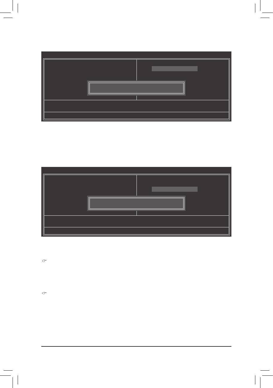
2-10 Load Fail-Safe Defaults
CMOS Setup Utility-Copyright (C) 1984-2011 Award Software
MB Intelligent Tweaker(M.I.T.)
Load Fail-Safe Defaults
Standard CMOS Features
Load Optimized Defaults
Advanced BIOS Features
Set Supervisor Password
Integrated Peripherals
Set User Password
Power Management Setup
Save & Exit Setup
Load Fail-Safe Defaults (Y/N)? N
PnP/PCICongurations
Exit Without Saving
PC Health Status
ESC: Quit
: Select Item F11: Save CMOS to BIOS
F8: Q-Flash F10: Save & Exit Setup F12: Load CMOS from BIOS
Load Fail-Safe Defaults
Press <Enter> on this item and then press the <Y> key to load the safest BIOS default settings.
In case system instability occurs, you may try to load Fail-Safe defaults, which are the safest and most stable
BIOS settings for the motherboard.
BIOS Setup - 34 -
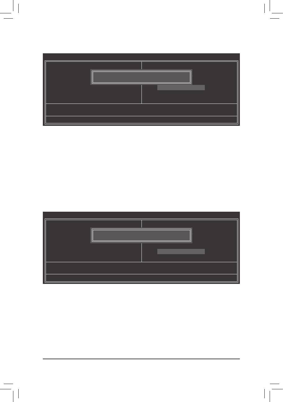
2-11 Load Optimized Defaults
CMOS Setup Utility-Copyright (C) 1984-2011 Award Software
MB Intelligent Tweaker(M.I.T.)
Load Fail-Safe Defaults
Standard CMOS Features
Load Optimized Defaults
Advanced BIOS Features
Set Supervisor Password
Integrated Peripherals
Set User Password
Power Management Setup
Save & Exit Setup
Load Optimized Defaults (Y/N)? N
PnP/PCICongurations
Exit Without Saving
PC Health Status
ESC: Quit
: Select Item F11: Save CMOS to BIOS
F8: Q-Flash F10: Save & Exit Setup F12: Load CMOS from BIOS
Load Optimized Defaults
Press <Enter> on this item and then press the <Y> key to load the optimal BIOS default settings.
The BIOS defaults settings help the system to operate in optimum state. Always load the Optimized defaults
after updating the BIOS or after clearing the CMOS values.
2-12 Set Supervisor/User Password
CMOS Setup Utility-Copyright (C) 1984-2011 Award Software
MB Intelligent Tweaker(M.I.T.)
Load Fail-Safe Defaults
Standard CMOS Features
Load Optimized Defaults
Advanced BIOS Features
Set Supervisor Password
Integrated Peripherals
Set User Password
Power Management Setup
Save & Exit Setup
Enter Password:
PnP/PCICongurations
Exit Without Saving
PC Health Status
ESC: Quit
: Select Item F11: Save CMOS to BIOS
F8: Q-Flash F10: Save & Exit Setup F12: Load CMOS from BIOS
Change/Set/DisablePassword
Press <Enter> on this item and type the password with up to 8 characters and then press <Enter>. You will
be requested to conrm the password. Type the password again and press <Enter>.
The BIOS Setup program allows you to specify two separate passwords:
Supervisor Password
When a system password is set and the Password Check item in Advanced BIOS Features is set to
Setup, you must enter the supervisor password for entering BIOS Setup and making BIOS changes.
When the Password Check item is set to System, you must enter the supervisor password (or user
password) at system startup and when entering BIOS Setup.
User Password
When the Password Check item is set to System, you must enter the supervisor password (or user
password) at system startup to continue system boot. In BIOS Setup, you must enter the supervisor
password if you wish to make changes to BIOS settings. The user password only allows you to view the
BIOS settings but not to make changes.
To clear the password, press <Enter> on the password item and when requested for the password, press
<Enter> again. The message "PASSWORD DISABLED" will appear, indicating the password has been can-
celled.
- 35 - BIOS Setup
2-13 Save & Exit Setup
CMOS Setup Utility-Copyright (C) 1984-2011 Award Software
MB Intelligent Tweaker(M.I.T.)
Load Fail-Safe Defaults
Standard CMOS Features
Load Optimized Defaults
Advanced BIOS Features
Save to CMOS and EXIT (Y/N)? Y
Set Supervisor Password
Integrated Peripherals
Set User Password
Power Management Setup
Save & Exit Setup
PnP/PCICongurations
Exit Without Saving
PC Health Status
ESC: Quit
: Select Item F11: Save CMOS to BIOS
F8: Q-Flash F10: Save & Exit Setup F12: Load CMOS from BIOS
Save Data to CMOS
Press <Enter> on this item and press the <Y> key. This saves the changes to the CMOS and exits the BIOS
Setup program. Press <N> or <Esc> to return to the BIOS Setup Main Menu.
2-14 Exit Without Saving
CMOS Setup Utility-Copyright (C) 1984-2011 Award Software
MB Intelligent Tweaker(M.I.T.)
Load Fail-Safe Defaults
Standard CMOS Features
Load Optimized Defaults
Advanced BIOS Features
Quit Without Saving (Y/N)? N
Set Supervisor Password
Integrated Peripherals
Set User Password
Power Management Setup
Save & Exit Setup
PnP/PCICongurations
Exit Without Saving
PC Health Status
ESC: Quit
: Select Item F11: Save CMOS to BIOS
F8: Q-Flash F10: Save & Exit Setup F12: Load CMOS from BIOS
AbandonallData
Press <Enter> on this item and press the <Y> key. This exits the BIOS Setup without saving the changes
made in BIOS Setup to the CMOS. Press <N> or <Esc> to return to the BIOS Setup Main Menu.
BIOS Setup - 36 -


