ASRock X79 Extreme4 – страница 2
Инструкция к Материнской Плате ASRock X79 Extreme4
2.5.2 Driver Installation and Setup
Install the graphics card drivers to your system. After that, you can enable the Multi-
®
Graphics Processing Unit (GPU) feature in the NVIDIA
nView system tray utility.
Please follow the below procedures to enable the multi-GPU feature.
®
For Windows
XP / XP 64-bit OS:
TM
(For SLI
mode only)
®
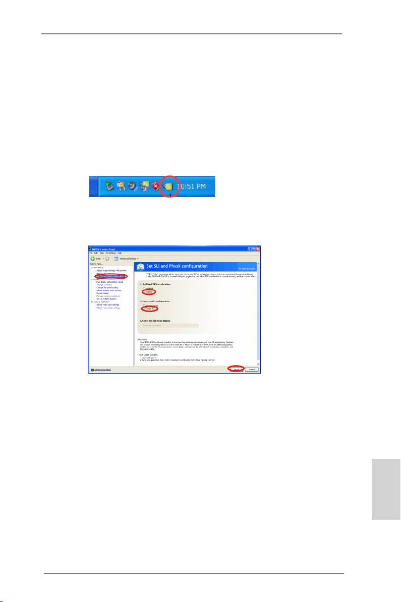
A. Double-click NVIDIA Settings icon on your Windows
taskbar.
B. From the pop-up menu, select Set SLI and PhysX conguration. In
Set PhysX GPU acceleration item, please select Enabled. In Select
an SLI conguration item, please select Enable SLI. And click Apply.
C. Reboot your system.
TM
D. You can freely enjoy the benet of SLI
feature.
English
21
ASRock X79 Extreme4 Motherboard
®
TM
TM
For Windows
Vista
/ Vista
64-bit / 7 / 7 64-bit OS:
TM
TM
(For SLI
and Quad SLI
mode)
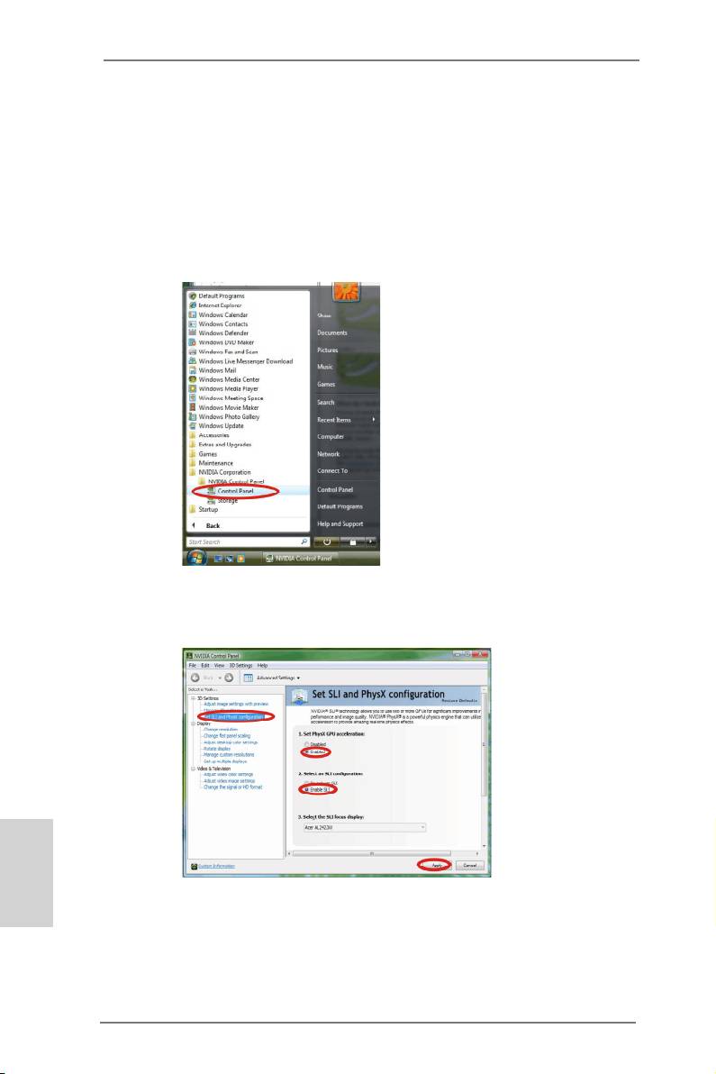
A. Click the Start icon on your Windows taskbar.
B. From the pop-up menu, select All Programs, and then click NVIDIA
Corporation.
C. Select NVIDIA Control Panel tab.
D. Select Control Panel tab.
E. From the pop-up menu, select Set SLI and PhysX conguration. In
Set PhysX GPU acceleration item, please select Enabled. In Select
an SLI conguration item, please select Enable SLI. And click Apply.
English
F. Reboot your system.
TM
TM
G. You can freely enjoy the benet of SLI
or Quad SLI
feature.
22
ASRock X79 Extreme4 Motherboard
®
TM
TM
For Windows
Vista
/ Vista
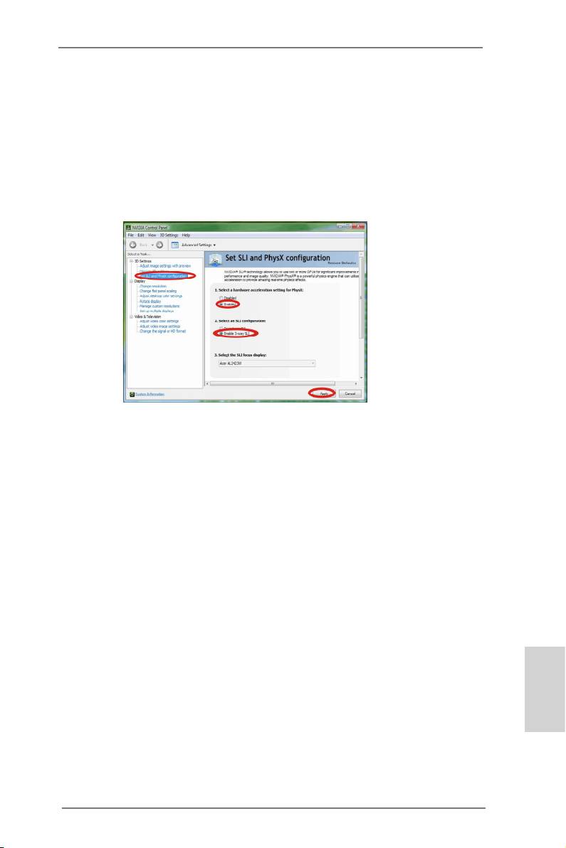
64-bit / 7 / 7 64-bit OS:
TM
(For 3-Way SLI
mode)
A. Follow step A to D on page 22.
B. From the pop-up menu, select Set SLI and PhysX conguration. In
Select a hardware acceleration setting for PhysX item, please
select Enabled. In Select an SLI conguration item, please select
Enable 3-way SLI. And click Apply.
C. Reboot your system.
TM
D. You can freely enjoy the benet of 3-Way SLI
feature.
TM
®
* SLI
appearing here is a registered trademark of NVIDIA
Technologies Inc., and is used
only for identication or explanation and to the owners’ benet, without intent to infringe.
English
23
ASRock X79 Extreme4 Motherboard
TM
TM
TM
2.6 CrossFireX
, 3-Way CrossFireX
and Quad CrossFireX
Operation
Guide
TM
TM
This motherboard supports CrossFireX
, 3-way CrossFireX
and Quad
TM
TM
CrossFireX
feature. CrossFireX
technology offers the most advantageous
means available of combining multiple high performance Graphics Processing
Units (GPU) in a single PC. Combining a range of different operating modes with
TM
intelligent software design and an innovative interconnect mechanism, CrossFireX
enables the highest possible level of performance and image quality in any 3D
TM
®
application. Currently CrossFireX
feature is supported with Windows
XP with
TM
TM
TM
Service Pack 2 / Vista
/ 7 OS. 3-way CrossFireX
and Quad CrossFireX
feature
®
TM
are supported with Windows
Vista
/ 7 OS only. Please check AMD website for
TM
TM
ATI
CrossFireX
driver updates.
1. If a customer incorrectly congures their system they will not see the
TM
TM
performance benets of CrossFireX
. All three CrossFireX
components, a
TM
TM
CrossFireX
Ready graphics card, a CrossFireX
Ready motherboard and a
TM
CrossFireX
Edition co-processor graphics card, must be installed correctly to
TM
benet from the CrossFireX
multi-GPU platform.
TM
2. If you pair a 12-pipe CrossFireX
Edition card with a 16-pipe card, both cards
TM
will operate as 12-pipe cards while in CrossFireX
mode.
2.6.1 Graphics Card Setup
TM
2.6.1.1 Installing Two CrossFireX
-Ready Graphics Cards
TM
TM
Different CrossFireX
cards may require different methods to enable CrossFireX
feature. In below procedures, we use Radeon HD 5770 as the example graphics
TM
card. For other CrossFireX
cards that AMD has released or will release in the
future, please refer to AMD graphics card manuals for detailed installation guide.
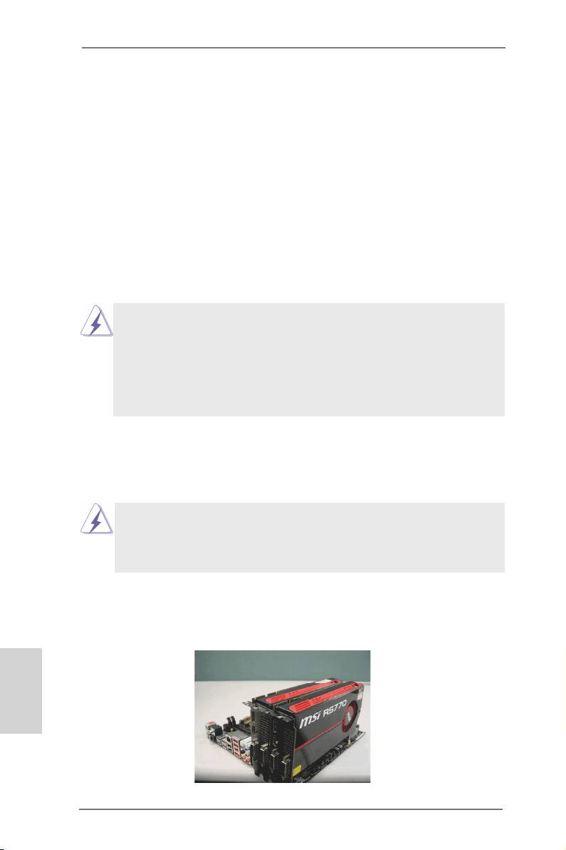
Step 1. Insert one Radeon graphics card into PCIE1 slot and the other Radeon
graphics card to PCIE3 slot. Make sure that the cards are properly seated
on the slots.
English
24
ASRock X79 Extreme4 Motherboard
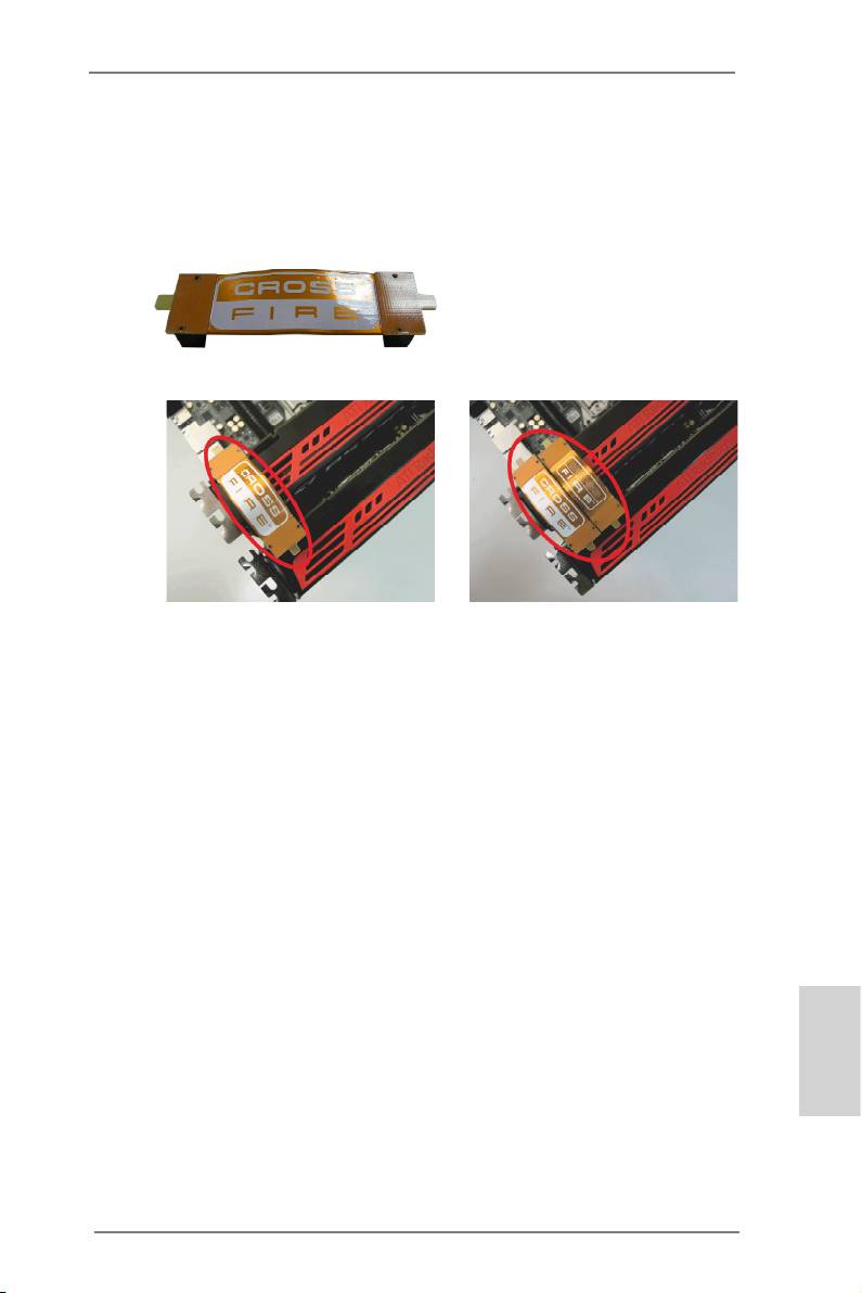
Step 2. Connect two Radeon graphics cards by installing CrossFire Bridge on
CrossFire Bridge Interconnects on the top of Radeon graphics cards.
(CrossFire Bridge is provided with the graphics card you purchase, not
bundled with this motherboard. Please refer to your graphics card vendor
for details.)
CrossFire Bridge
or
Step 3. Connect the DVI monitor cable to the DVI connector on the Radeon
graphics card on PCIE1 slot. (You may use the DVI to D-Sub adapter to
convert the DVI connector to D-Sub interface, and then connect the D-Sub
monitor cable to the DVI to D-Sub adapter.)
English
25
ASRock X79 Extreme4 Motherboard
TM
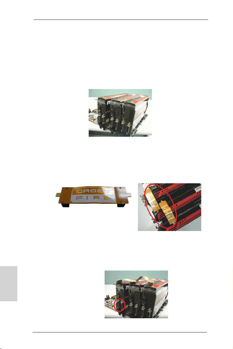
2.6.1.2 Installing Three CrossFireX
-Ready Graphics Cards
TM
Step 1. Install the identical 3-Way CrossFireX
-ready graphics cards that are
®
AMD
certified because different types of graphics cards will not work
together properly. (Even the GPU chips version shall be the same.) Insert
one graphics card into PCIE1 slot, another graphics card to PCIE3 slot,
and the other graphics card to PCIE4 slot. Make sure that the cards are
properly seated on the slots.
TM
Step 4. Use one CrossFire
Bridge to connect Radeon graphics cards on PCIE1
TM
and PCIE3 slots, and use the other CrossFire
Bridge to connect Radeon
TM
graphics cards on PCIE3 and PCIE4 slots. (CrossFire
Bridge is provided
with the graphics card you purchase, not bundled with this motherboard.
Please refer to your graphics card vendor for details.)
TM
CrossFire
Bridge
Step 5. Connect the DVI monitor cable to the DVI connector on the Radeon graph-
ics card on PCIE1 slot. (You may use the DVI to D-Sub adapter to convert
the DVI connector to D-Sub interface, and then connect the D-Sub monitor
cable to the DVI to D-Sub adapter.)
English
26
ASRock X79 Extreme4 Motherboard
2.6.2 Driver Installation and Setup
Step 1. Power on your computer and boot into OS.
Step 2. Remove the AMD driver if you have any VGA driver installed in your
system.
The Catalyst Uninstaller is an optional download. We recommend using this
utility to uninstall any previously installed Catalyst drivers prior to installation.
TM
Please check AMD website for ATI
driver updates.
Step 3. Install the required drivers to your system.
®
For Windows
XP OS:
®
A. AMD recommends Windows
XP Service Pack 2 or higher to be
®
installed (If you have Windows
XP Service Pack 2 or higher installed
in your system, there is no need to download it again):
http://www.microsoft.com/windowsxp/sp2/default.mspx
B. You must have Microsoft .NET Framework installed prior to
downloading and installing the CATALYST Control Center. Please
check Microsoft website for details.
®
TM
For Windows
7 / Vista
OS:
Install the CATALYST Control Center. Please check AMD website for de-
tails.
Step 4. Restart your computer.
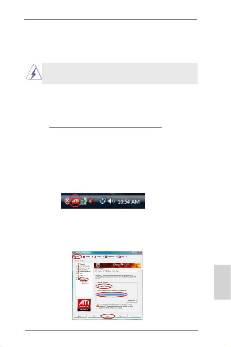
Step 5. Install the VGA card drivers to your system, and restart your computer.
®
Then you will nd “ATI Catalyst Control Center” on your Windows
taskbar.
ATI Catalyst Control Center
Step 6. Double-click “ATI Catalyst Control Center”. Click “View”, select “CrossFi-
TM
TM
reX
”, and then check the item “Enable CrossFireX
”. Select “2 GPUs”
and click “Apply” (if you install two Radeon graphics cards). Select “3
GPUs” and click “OK” (if you install three Radeon graphics cards).
English
27
ASRock X79 Extreme4 Motherboard

TM
TM
Although you have selected the option “Enable CrossFire
”, the CrossFireX
function may not work actually. Your computer will automatically reboot. After
restarting your computer, please conrm whether the option “Enable
TM
CrossFire
” in “ATI Catalyst Control Center” is selected or not; if not, please
TM
select it again, and then you are able to enjoy the benet of CrossFireX
feature.
TM
TM
Step 7. You can freely enjoy the benet of CrossFireX
, 3-Way CrossFireX
or
TM
Quad CrossFireX
feature.
TM
* CrossFireX
appearing here is a registered trademark of AMD Technologies Inc., and is
used only for identication or explanation and to the owners’ benet, without intent to infringe.
TM
* For further information of AMD CrossFireX
technology, please check AMD website for
updates and details.
2.7 Surround Display Feature
This motherboard supports Surround Display upgrade. With the external add-on PCI
Express VGA cards, you can easily enjoy the benets of Surround Display feature.
For the detailed instruction, please refer to the document at the following path in the
Support CD:
..\ Surround Display Information
English
28
ASRock X79 Extreme4 Motherboard
2.8 ASRock Smart Remote Installation Guide
ASRock Smart Remote is only used for ASRock motherboard with CIR header.
Please refer to below procedures for the quick installation and usage of ASRock
Smart Remote.
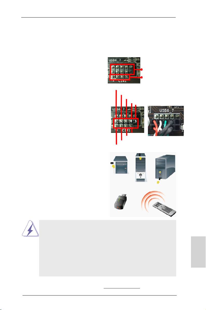
Step1. Find the CIR header located next
to the USB 2.0 header on ASRock
USB 2.0 header (9-pin, black)
motherboard.
CIR header (4-pin, gray)
USB_PWR
Step2. Connect the front USB cable to the
P-
USB 2.0 header (as below, pin 1-5)
P+
and the CIR header. Please make
GND
DUMMY
sure the wire assignments and the
pin assignments are matched
correctly.
GND
IRTX
IRRX
ATX+5VSB
Step3. Install Multi-Angle CIR Receiver to
the front USB port. If Multi-Angle
CIR Receiver cannot successfully
receive the infrared signals from
MCE Remote Controller, please try
to install it to the other front USB
port.
3 CIR sensors in different angles
1. Only one of the front USB port can support CIR function. When
the CIR function is enabled, the other port will remain USB
function.
2. Multi-Angle CIR Receiver is used for front USB only. Please do
not use the rear USB bracket to connect it on the rear panel.
Multi-Angle CIR Receiver can receive the multi-direction infrared
signals (top, down and front), which is compatible with most of
English
the chassis on the market.
3. The Multi-Angle CIR Receiver does not support Hot-Plug
function. Please install it before you boot the system.
* ASRock Smart Remote is only supported by some of ASRock motherboards. Please refer to
ASRock website for the motherboard support list: http://www.asrock.com
29
ASRock X79 Extreme4 Motherboard
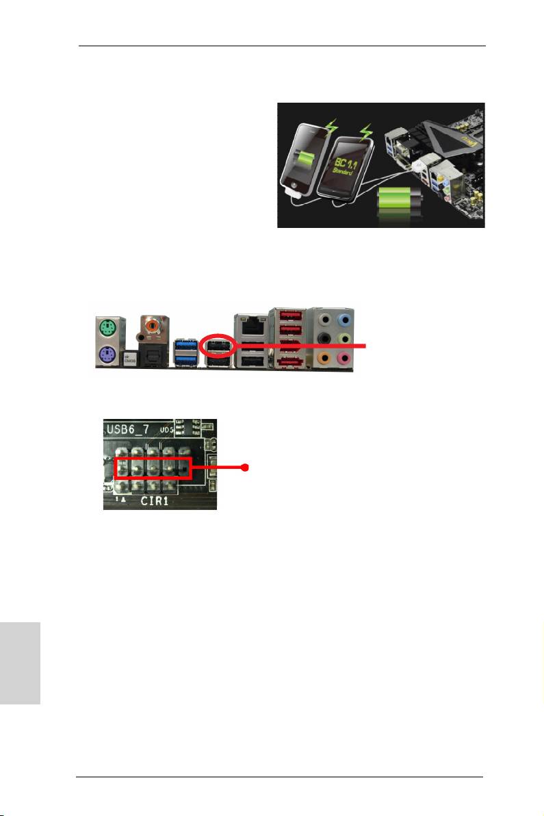
2.9 ASRock XFast Charger Operation Guide
ASRock XFast Charger is the best and
fastest technology to charge your mobile
devices via PC. With the superb XFast
Charger USB port, users are assured to
enjoy the quick charging experience
anytime. In addition to Apple devices, it
is also capable of Charging the BC 1.1
standard smart devices. Please refer to
below instruction for proper operation.
This motherboard provides two USB ports for ASRock XFast Charger:
1. USB 2.0 port (USB0) on the I/O panel
see p.3 No. 14
2. USB 2.0 port (USB6) header
see p.2 No. 30
With ASRock XFast Charger feature, you can freely enjoy the quick charging
convenience by installing the USB cable on these two ports.
English
30
ASRock X79 Extreme4 Motherboard
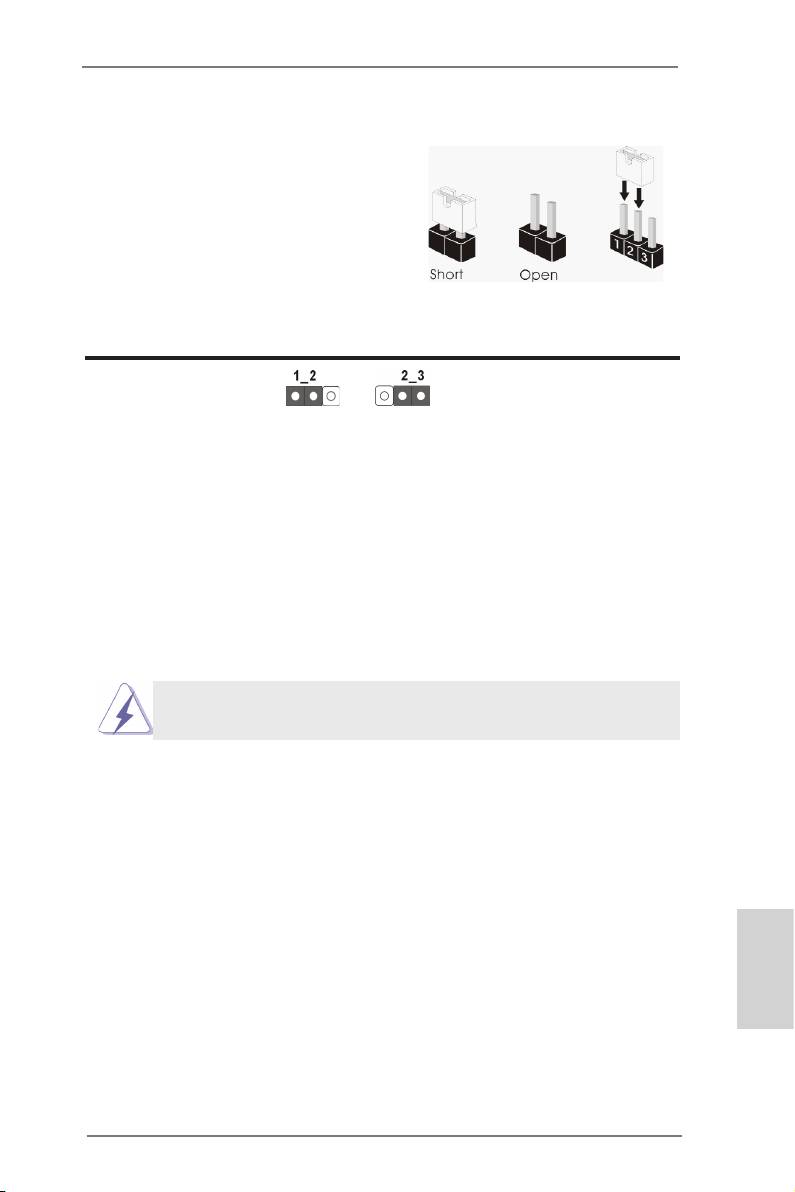
2.10 Jumpers Setup
The illustration shows how jumpers are
setup. When the jumper cap is placed on
pins, the jumper is “Short”. If no jumper cap
is placed on pins, the jumper is “Open”. The
illustration shows a 3-pin jumper whose
pin1 and pin2 are “Short” when jumper cap
is placed on these 2 pins.
Jumper Setting Description
Clear CMOS Jumper
(CLRCMOS1)
(see p.2, No. 27)
Clear CMOSDefault
Note: CLRCMOS1 allows you to clear the data in CMOS. To clear and reset the
system parameters to default setup, please turn off the computer and unplug
the power cord from the power supply. After waiting for 15 seconds, use a
jumper cap to short pin2 and pin3 on CLRCMOS1 for 5 seconds. However,
please do not clear the CMOS right after you update the BIOS. If you need
to clear the CMOS when you just nish updating the BIOS, you must boot
up the system rst, and then shut it down before you do the clear-CMOS ac-
tion. Please be noted that the password, date, time, user default prole, 1394
GUID and MAC address will be cleared only if the CMOS battery is removed.
The Clear CMOS Switch has the same function as the Clear CMOS
jumper.
English
31
ASRock X79 Extreme4 Motherboard
2.11 Onboard Headers and Connectors
Onboard headers and connectors are NOT jumpers. Do NOT place
jumper caps over these headers and connectors. Placing jumper caps
over the headers and connectors will cause permanent damage of the
motherboard!
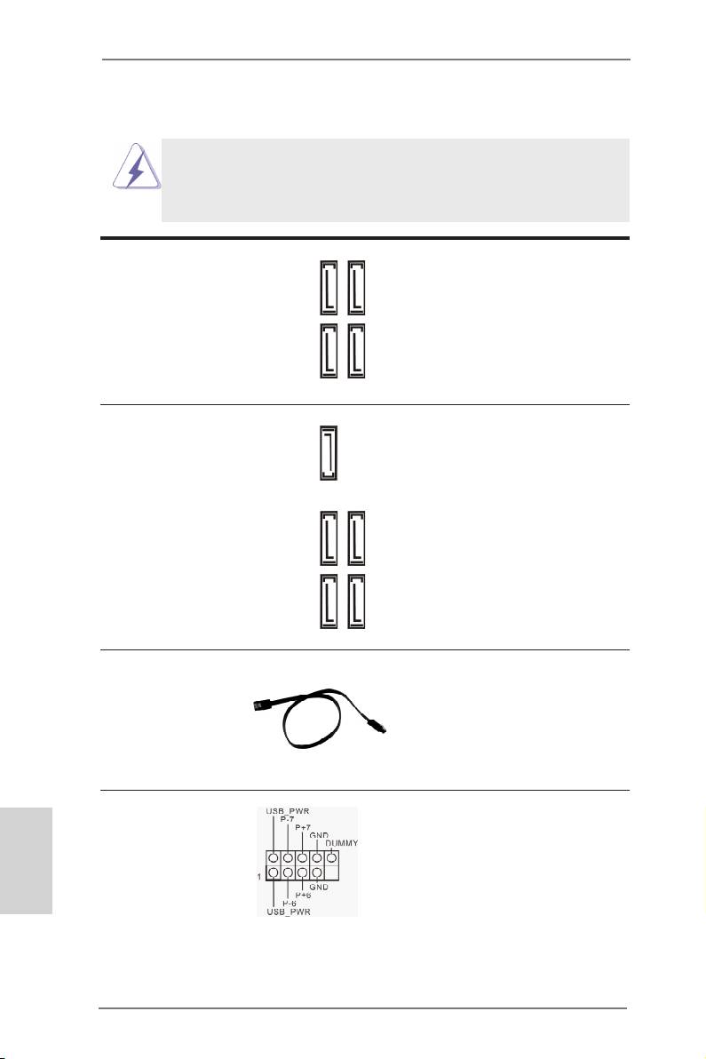
Serial ATA2 Connectors These four Serial ATA2
(SATA2_0_1: see p.2, No. 15)
(SATA2) connectors support
(SATA2_2_3: see p.2, No. 14)
SATA data cables for internal
storage devices. The current
SATA2 interface allows up to
3.0 Gb/s data transfer rate.
SATA2_0 SATA2_2
SATA2_1 SATA_3
Serial ATA3 Connectors These ve Serial ATA3
(SATA3_0_1: see p.2, No. 16)
(SATA3) connectors support
(SATA3_A0_A1: see p.2, No. 17)
SATA data cables for internal
SATA3_A2
(SATA3_A2: see p.2, No. 11)
storage devices. The current
SATA3 interface allows up to
6.0 Gb/s data transfer rate.
SATA3_A0 SATA3_0
SATA3_A1 SATA3_1
Serial ATA (SATA) Either end of the SATA data
Data Cable cable can be connected to the
(Optional)
SATA / SATA2 / SATA3 hard
disk or the SATA2 / SATA3
connector on this motherboard.
USB 2.0 Headers Besides six default USB 2.0
English
(9-pin USB_6_7)
ports on the I/O panel, there
(see p.2 No. 30)
are three USB 2.0 headers on
this motherboard. Each USB 2.0
header can support two USB
2.0 ports.
32
ASRock X79 Extreme4 Motherboard
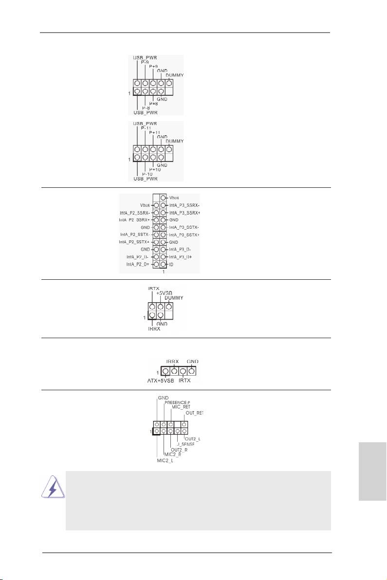
(9-pin USB_8_9)
(see p.2 No. 29)
(9-pin USB_10_11)
(see p.2 No. 28)
USB 3.0 Header Besides two default USB 3.0
(19-pin USB3_2_3)
ports on the I/O panel, there is
(see p.2 No. 10)
one USB 3.0 header on this
motherboard. This USB 3.0
header can support two USB
3.0 ports.
Infrared Module Header This header supports an
(5-pin IR1)
optional wireless transmitting
(see p.2 No. 33)
and receiving infrared module.
Consumer Infrared Module Header This header can be used to
(4-pin CIR1)
connect the remote
(see p.2 No. 31)
controller receiver.
Front Panel Audio Header This is an interface for front
(9-pin HD_AUDIO1)
panel audio cable that allows
(see p.2 No. 36)
convenient connection and
control of audio devices.
1. High Denition Audio supports Jack Sensing, but the panel wire on
English
the chassis must support HDA to function correctly. Please follow the
instruction in our manual and chassis manual to install your system.
2. If you use AC’97 audio panel, please install it to the front panel audio
header as below:
33
ASRock X79 Extreme4 Motherboard
A. Connect Mic_IN (MIC) to MIC2_L.
B. Connect Audio_R (RIN) to OUT2_R and Audio_L (LIN) to OUT2_L.
C. Connect Ground (GND) to Ground (GND).
D. MIC_RET and OUT_RET are for HD audio panel only. You don’t
need to connect them for AC’97 audio panel.
E. To activate the front mic.
®
For Windows
XP / XP 64-bit OS:
Select “Mixer”. Select “Recorder”. Then click “FrontMic”.
®
TM
TM
For Windows
7 / 7 64-bit / Vista
/ Vista
64-bit OS:
Go to the "FrontMic" Tab in the Realtek Control panel. Adjust
“Recording Volume”.
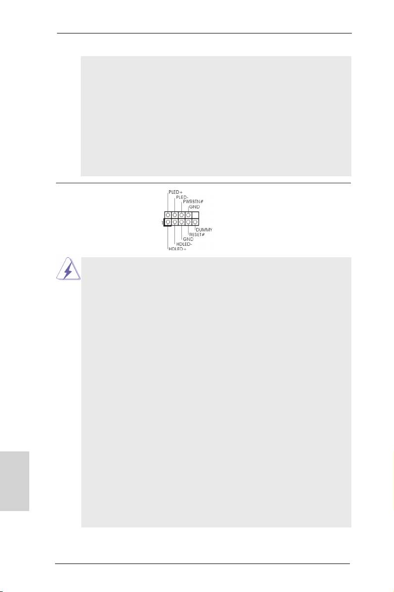
System Panel Header This header accommodates
(9-pin PANEL1)
several system front panel
(see p.2 No. 25)
functions.
Connect the power switch, reset switch and system status indicator on the
chassis to this header according to the pin assignments below. Note the
positive and negative pins before connecting the cables.
PWRBTN (Power Switch):
Connect to the power switch on the chassis front panel. You may congure
the way to turn off your system using the power switch.
RESET (Reset Switch):
Connect to the reset switch on the chassis front panel. Press the reset
switch to restart the computer if the computer freezes and fails to perform a
normal restart.
PLED (System Power LED):
Connect to the power status indicator on the chassis front panel. The LED
is on when the system is operating. The LED keeps blinking when the sys-
tem is in S1 sleep state. The LED is off when the system is in S3/S4 sleep
state or powered off (S5).
HDLED (Hard Drive Activity LED):
Connect to the hard drive activity LED on the chassis front panel. The LED
is on when the hard drive is reading or writing data.
English
The front panel design may differ by chassis. A front panel module mainly
consists of power switch, reset switch, power LED, hard drive activity LED,
speaker and etc. When connecting your chassis front panel module to this
header, make sure the wire assignments and the pin assign-ments are
matched correctly.
34
ASRock X79 Extreme4 Motherboard
Chassis Speaker Header Please connect the chassis
(4-pin SPEAKER 1)
speaker to this header.
(see p.12 No. 24)
Power LED Header Please connect the chassis
(3-pin PLED1)
power LED to this header to
(see p.12 No. 21)
indicate system power status.
The LED is on when the system
is operating. The LED keeps
blinking in S1 state. The LED is
off in S3/S4 state or S5 state
(power off).
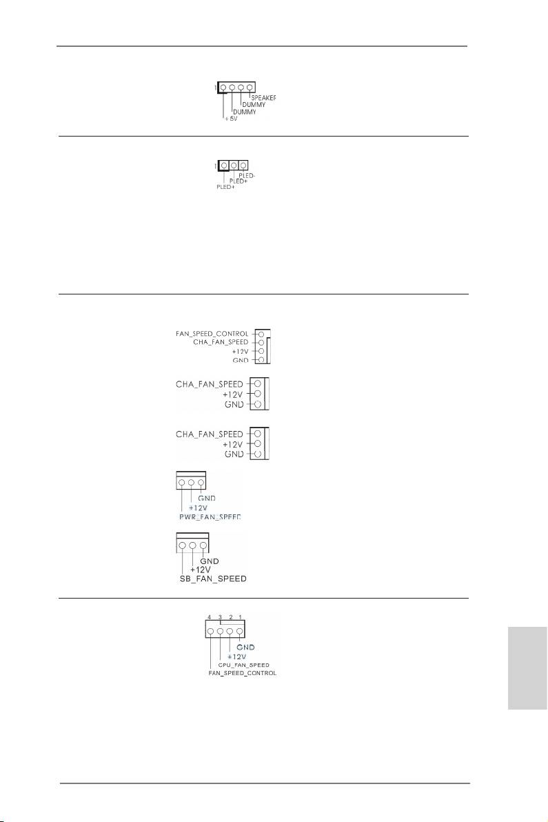
Chassis, Power and SB Fan Connectors Please connect the fan cables
(4-pin CHA_FAN1)
to the fan connectors and
(see p.12 No. 9)
match the black wire to the
ground pin. CHA_FAN1,
CHA_FAN2 and CHA_FAN3
(3-pin CHA_FAN2)
support Fan Control. SB_FAN1
(see p.12 No. 13)
Supports Quiet Fan.
(3-pin CHA_FAN3)
(see p.12 No. 20)
(3-pin PWR_FAN1)
(see p.12 No. 7)
(3-pin SB_FAN1)
(see p.12 No. 12)
CPU Fan Connectors Please connect the CPU fan
(4-pin CPU_FAN1)
cable to the connector and
(see p.12 No. 6)
match the black wire to the
ground pin.
English
35
ASRock X79 Extreme4 Motherboard
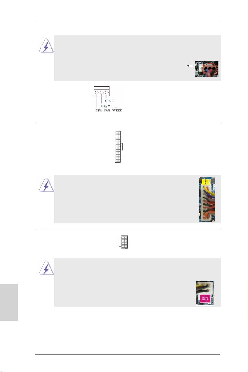
Though this motherboard provides 4-Pin CPU fan (Quiet Fan) support, the 3-Pin
CPU fan still can work successfully even without the fan speed control function.
If you plan to connect the 3-Pin CPU fan to the CPU fan connector on this
motherboard, please connect it to Pin 1-3.
Pin 1-3 Connected
3-Pin Fan Installation
(3-pin CPU_FAN2)
(see p.2 No. 4)
12
24
ATX Power Connector Please connect an ATX power
(24-pin ATXPWR1)
supply to this connector.
(see p.2 No. 8)
1
13
Though this motherboard provides 24-pin ATX power connector,
12
24
it can still work if you adopt a traditional 20-pin ATX power supply.
To use the 20-pin ATX power supply, please plug your
power supply along with Pin 1 and Pin 13.
20-Pin ATX Power Supply Installation
1
13
ATX 12V Power Connector Please connect an ATX 12V
5 1
(8-pin ATX12V1)
power supply to this connector.
8 4
(see p.2 No. 1)
Though this motherboard provides 8-pin ATX 12V power connector, it can still work
if you adopt a traditional 4-pin ATX 12V power supply. To use the 4-pin ATX power
supply, please plug your power supply along with Pin 1 and Pin 5.
5 1
English
4-Pin ATX 12V Power Supply Installation
8 4
36
ASRock X79 Extreme4 Motherboard
SLI/XFIRE Power Connector It is not necessary to use this
(4-pin SLI/XFIRE_PWR1)
connector, but please connect it
(see p.2 No. 44)
with a hard disk power
connecor when two graphics
SLI/XFIRE_POWER1
cards are plugged to this
motherboard.
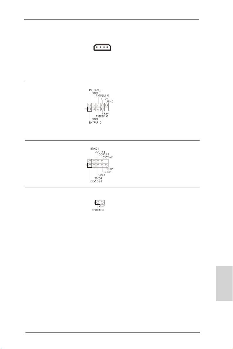
IEEE 1394 Header Besides one default IEEE 1394
(9-pin FRONT_1394)
port on the I/O panel, there
(see p.2 No. 32)
is one IEEE 1394 header
(FRONT_1394) on this
motherboard. This IEEE 1394
header can support one IEEE
1394 port.
Serial port Header This COM1 header supports a
(9-pin COM1)
serial port module.
(see p.2 No. 34)
HDMI_SPDIF Header HDMI_SPDIF header, providing
(2-pin HDMI_SPDIF1)
SPDIF audio output to HDMI
(see p.2 No. 35)
VGA card, allows the system to
connect HDMI Digital TV/
projector/LCD devices. Please
connect the HDMI_SPDIF
connector of HDMI VGA card to
this header.
English
37
ASRock X79 Extreme4 Motherboard
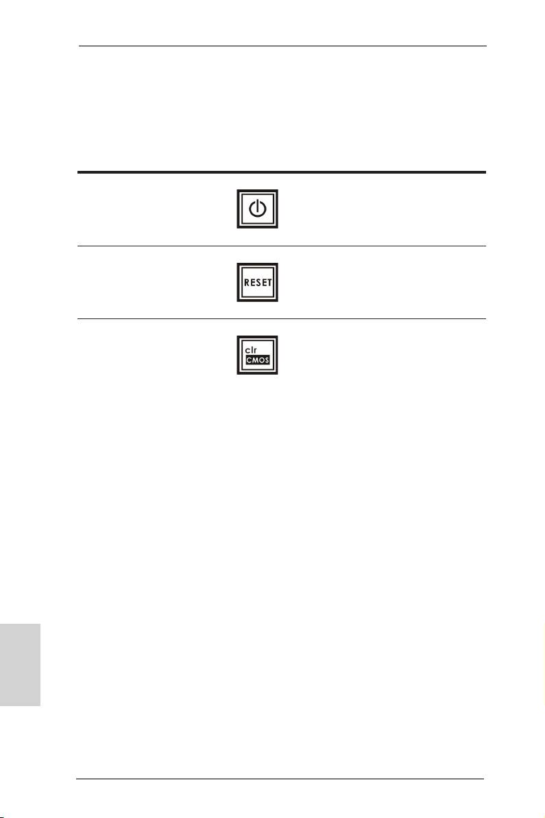
2.12 Smart Switches
The motherboard has three smart switches: power switch, reset switch and clear
CMOS switch, allowing users to quickly turn on/off or reset the system to clear the
CMOS values.
Power Switch Power Switch is a smart switch,
(PWRBTN)
allowing users to quickly turn
(see p.2 No. 23)
on/off the system.
Reset Switch Reset Switch is a smart switch,
(RSTBTN)
allowing users to quickly reset
(see p.2 No. 22)
the system.
Clear CMOS Switch Clear CMOS Switch is a smart
(CLRCBTN)
switch, allowing users to quickly
(see p.3 No. 17)
clear the CMOS values.
English
38
ASRock X79 Extreme4 Motherboard

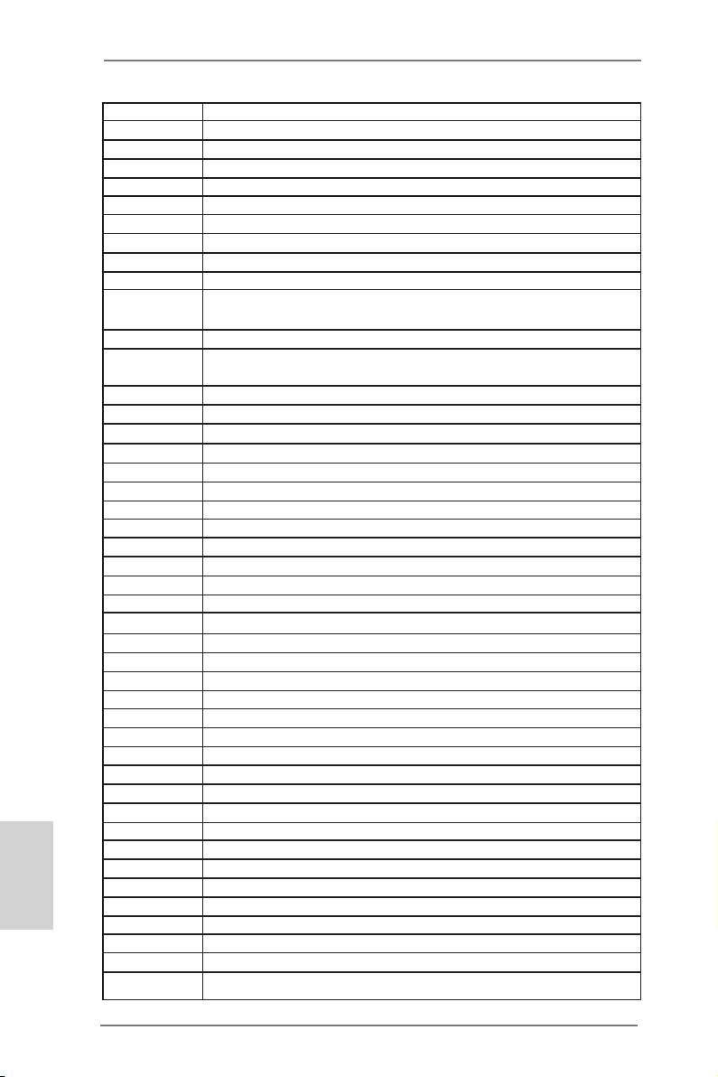
2.13 Dr. Debug
Dr. Debug is used to provide code information, which makes troubleshooting even
easier. Please see the diagrams below for reading the Dr. Debug codes.
Status Code Description
0x00 Not used
0x01 Power on. Reset type detection (soft/hard)
0x02 AP initialization before microcode loading
0x03 North Bridge initialization before microcode loading
0x04 South Bridge initialization before microcode loading
0x05 OEM initialization before microcode loading
0x06 Microcode loading
0x07 AP initialization after microcode loading
0x08 North Bridge initialization after microcode loading
0x09 South Bridge initialization after microcode loading
0x0A OEM initialization after microcode loading
0x0B Cache initialization
0x0C – 0x0D Reserved for future AMI SEC error codes
0x0E Microcode not found
0x0F Microcode not loaded
0x10 PEI Core is started
0x11 Pre-memory CPU initialization is started
0x12 Pre-memory CPU initialization (CPU module specic)
0x13 Pre-memory CPU initialization (CPU module specic)
0x14 Pre-memory CPU initialization (CPU module specic)
0x15 Pre-memory North Bridge initialization is started
0x16 Pre-Memory North Bridge initialization (North Bridge module specic)
0x17 Pre-Memory North Bridge initialization (North Bridge module specic)
0x18 Pre-Memory North Bridge initialization (North Bridge module specic)
0x19 Pre-memory South Bridge initialization is started
0x1A Pre-memory South Bridge initialization (South Bridge module specic)
0x1B Pre-memory South Bridge initialization (South Bridge module specic)
0x1C Pre-memory South Bridge initialization (South Bridge module specic)
0x1D – 0x2A OEM pre-memory initialization codes
0x2B Memory initialization. Serial Presence Detect (SPD) data reading
0x2C Memory initialization. Memory presence detection
0x2D Memory initialization. Programming memory timing information
0x2E Memory initialization. Conguring memory
0x2F Memory initialization (other)
0x30 Reserved for ASL
0x31 Memory Installed
0x32 CPU post-memory initialization is started
English
0x33 CPU post-memory initialization. Cache initialization
0x34 CPU post-memory initialization. Application Processor(s) (AP) initialization
0x35 CPU post-memory initialization. Boot Strap Processor (BSP) selection
0x36 CPU post-memory initialization. System Management Mode (SMM)
initialization
39
ASRock X79 Extreme4 Motherboard
0x37 Post-Memory North Bridge initialization is started
0x38 Post-Memory North Bridge initialization (North Bridge module specic)
0x39 Post-Memory North Bridge initialization (North Bridge module specic)
0x3A Post-Memory North Bridge initialization (North Bridge module specic)
0x3B Post-Memory South Bridge initialization is started
0x3C Post-Memory South Bridge initialization (South Bridge module specic)
0x3D Post-Memory South Bridge initialization (South Bridge module specic)
0x3E Post-Memory South Bridge initialization (South Bridge module specic)
0x3F-0x4E OEM post memory initialization codes
0x4F DXE IPL is started
0x50 Memory initialization error. Invalid memory type or incompatible memory
speed
0x51 Memory initialization error. SPD reading has failed
0x52 Memory initialization error. Invalid memory size or memory modules do not
match
0x53 Memory initialization error. No usable memory detected
0x54 Unspecied memory initialization error
0x55 Memory not installed
0x56 Invalid CPU type or Speed
0x57 CPU mismatch
0x58 CPU self test failed or possible CPU cache error
0x59 CPU micro-code is not found or micro-code update is failed
0x5A Internal CPU error
0x5B reset PPI is not available
0x5C-0x5F Reserved for future AMI error codes
0xE0 S3 Resume is stared (S3 Resume PPI is called by the DXE IPL)
0xE1 S3 Boot Script execution
0xE2 Video repost
0xE3 OS S3 wake vector call
0xE4-0xE7 Reserved for future AMI progress codes
0xE8 S3 Resume Failed
0xE9 S3 Resume PPI not Found
0xEA S3 Resume Boot Script Error
0xEB S3 OS Wake Error
0xEC-0xEF Reserved for future AMI error codes
0xF0 Recovery condition triggered by rmware (Auto recovery)
0xF1 Recovery condition triggered by user (Forced recovery)
0xF2 Recovery process started
0xF3 Recovery rmware image is found
English
0xF4 Recovery rmware image is loaded
0xF5-0xF7 Reserved for future AMI progress codes
0xF8 Recovery PPI is not available
0xF9 Recovery capsule is not found
0xFA Invalid recovery capsule
0xFB – 0xFF Reserved for future AMI error codes
0x60 DXE Core is started
0x61 NVRAM initialization
40
ASRock X79 Extreme4 Motherboard
