3B Scientific Osteoporosis Model: инструкция
Раздел: Товары для здоровья
Тип:
Инструкция к 3B Scientific Osteoporosis Model
A95

®
Latin A95
1 Processus spinosus
2 Processus transversus
3 Processus articularis superior
4 Facies articularis superior
5 Fovea costalis
6 Facies articularis inferior
7 Corpus vertebrae
8a Facies intervertebralis superior
8b Facies intervertebralis superior (with osteoporotic and degenerative changes)
9 Vertebra thoracica XI
10 Osteophytes [engl.] (degenerative change)
11a Discus intervertebralis
11b Discus intervertebralis (with degenerative changes)
12 Incisura vertebralis inferior
13 Vertebra thoracica XII
14a Substantia spongiosa (Trabeculae) (with osteoporotic and degenerative changes)
14b Substantia spongiosa (Trabeculae)
15 Trabeculae

®
English
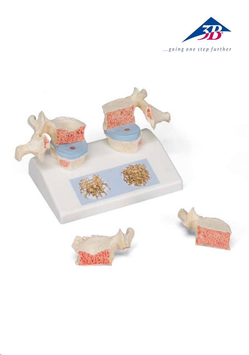
Osteoporosis Model
Impressive didactic model for comparing osteoporotic and normal thoracic vertebrae. Ideal for medical
studies and patient consultation.The 11th and 12th thoracic vertebrae are shown.
Reproductions of sequential osteoporotic thoracic vertebrae with narrower intervertebral disc are located
on the left of the stand. The upper vertebra is divided in the middle. The magnetically attached vertebral
half can be removed easily to show the cut surfaces.This allows clear visualisation of the fractured upper
part of the vertebral body caused by sintering, i.e. collapse of the bony substance in the course and as a
result of osteoporosis. Degenerative changes in the bone, manifested as osteophytes, are also identifiable.
For comparison, reproductions of two corresponding healthy vertebrae with intervertebral disc are
provided on the right side. One half of the upper vertebral body is also magnetically attached and can
be removed.
Each set of vertebrae also has a sticker on the stand showing two 3D micro CT images obtained from bone
biopsies. These illustrate the microarchitecture of the osteoporotic bone, which has a lower bone density
compared to healthy bone.
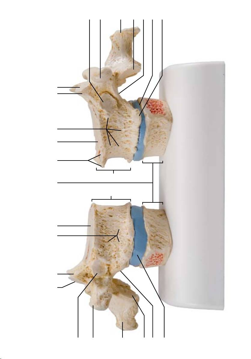
A-1 Lateral view of a healthy 11th thoracic vertebra with below adjacent intervertebral disc and
12th thoracic vertebra (reduced)
A-2 Lateral view of an osteoporotic 11th thoracic vertebra with degenerative changes with below
adjacent intervertebral disc and 12th thoracic vertebra (reduced)
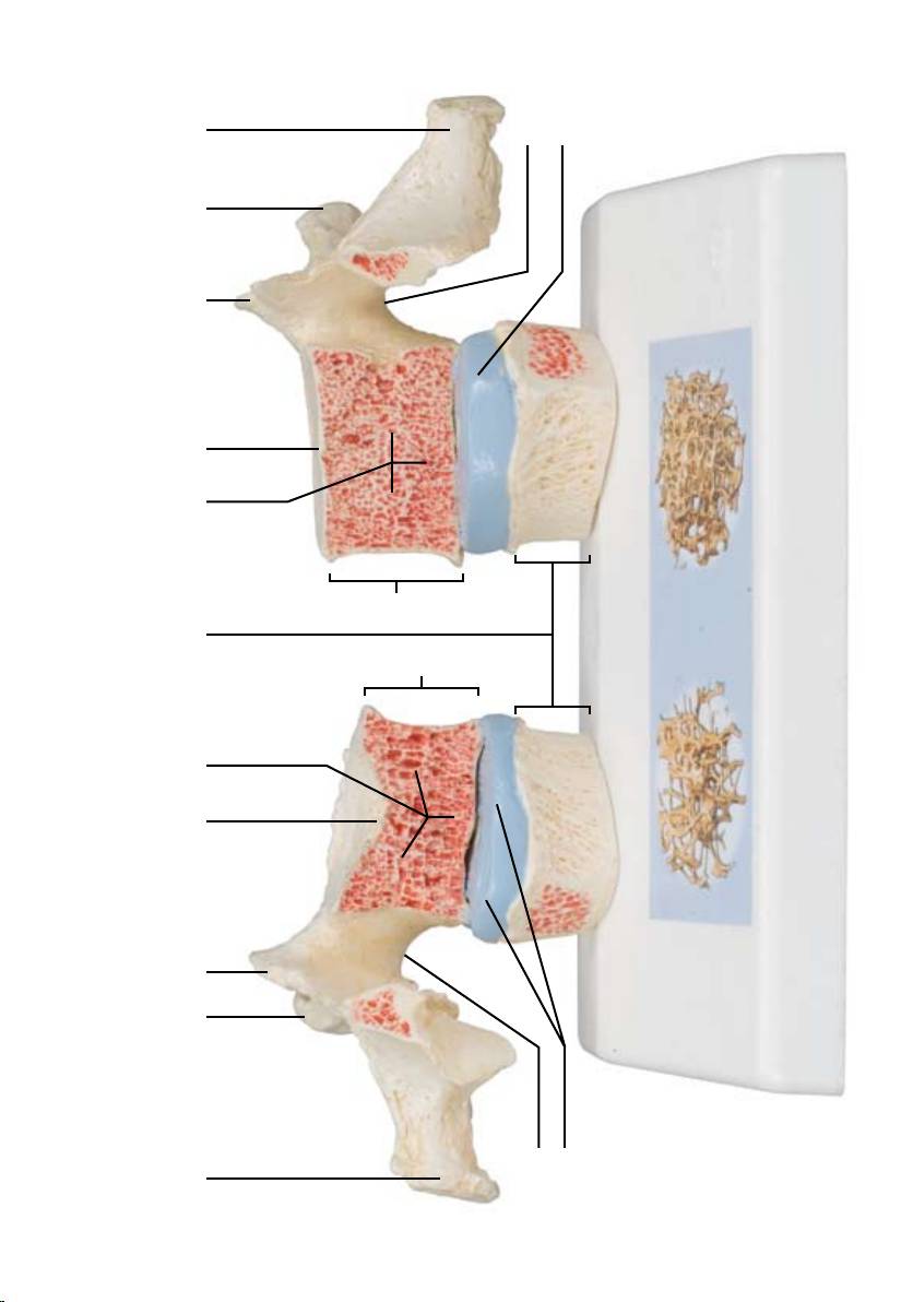
B-1 Midsagittal section through body of osteoporotic 11th thoracic vertebra with degenerative
changes
B-2 Midsagittal section through body of healthy 11th thoracic vertebra
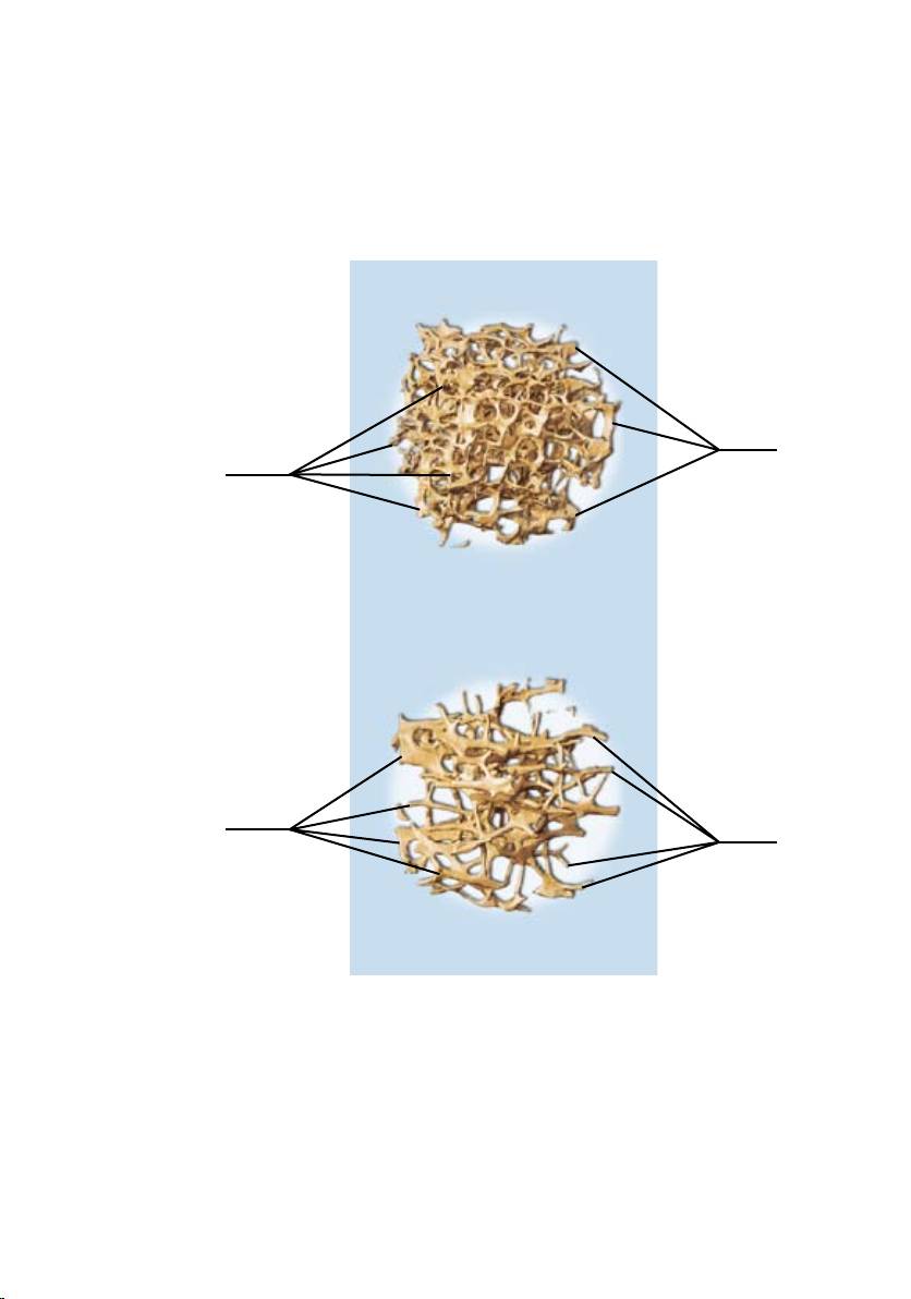
C-1 High resolution micro-CT 3D-image reconstruction: biopsy of osteoporotic trabecular bone
showing reduced densitiy and change of architecture
C-2 High resolution micro-CT 3D-image reconstruction: biopsy of healthy trabecular bone
1 Spinous process
2 Transverse process
3 Superior articular process
4 Superior articular facet
5 Costal facet
6 Inferior articular facet
7 Body of vertebra
8a Superior intervertebral surface of body of vertebra
8b Superior intervertebral surface of body of vertebra (with osteoporotic and degenerative changes)
9 11th thoracic vertebra
10 Osteophytes (degenerative change)
11a Intervertebral disc
11b Intervertebral disc (with degenerative changes)
12 Inferior vertebra notch
13 12th thoracic vertebra
14a Cancellous bone (with osteoporotic and degenerative changes)
14b Cancellous bone
15 Trabeculae of bone

®
Deutsch Osteoporose Modell
Osteoporose didaktisch eindrucksvoll präsentiert als Vergleich zwischen osteoporotischen und physiolo-
gischen Brustwirbeln. Dieses Modell ist ideal für die medizinische Ausbildung und das Patientengespräch.
Es handelt sich dabei jeweils um den 11. und 12 Brustwirbel.
Auf der linken Seite des Sockels sind Abformungen aufeinander folgender osteoporotischer Brustwirbel
mit verschmälerter Bandscheibe positioniert. Der obere Wirbelkörper ist in der Mittelebene getrennt.
Die magnetisch fixierte Wirbelhälfte ist leicht abnehmbar, so dass die Schnittflächen sichtbar werden.
Dadurch ist der Deckeneinbruch des Wirbelkörpers gut zu erkennen welcher als Folge der Sinterung, d.h.
des Zusammensackens der Knochensubstanz im Verlauf und als Folge der Osteoporose entstanden ist.
Außerdem sind degenerative Veränderungen am Knochen, in Form von Osteophyten, erkennbar.
Auf der rechten Seite des Sockels befinden sich zum Vergleich zwei korrespondierende Abformungen
gesunder Wirbel mit Zwischenwirbelscheibe. Die Halbseite des oberen Wirbelkörpers ist ebenfalls mittels
Magnet abnehmbar befestigt.
Ergänzt werden die Wirbeldarstellungen durch jeweils einen Aufkleber auf dem Sockel mit zwei 3D-Micro-
CT Darstellungen, gewonnen mittels Knochenbiopsien. Hierdurch wird die Mikroarchitektur des osteo-
porotischen Knochens, welcher im Vergleich zu einem gesunden Knochen eine geringere Knochendichte
aufweist, anschaulich.
A-1 Seitenansicht eines gesunden 11. Brustwirbels mit unten angrenzender Bandscheibe und
12. Brustwirbel (reduziert)
A-2 Seitenansicht eines osteoporotisch und degenerativ veränderten 11. Brustwirbels mit unten
angrenzender Bandscheibe und 12. Brustwirbel (reduziert)
B-1 Mediosagittalschnitt durch den Wirbelkörper eines osteoporotischen 11. Brustwirbels mit
degenerativen Veränderungen
B-2 Mediosagittalschnitt durch den gesunden Wirbelkörper eines 11. Brustwirbels
C-1 Hochauflösende Micro-CT 3D-Bildrekonstruktion: Biopsat eines osteoporotischen trabekulären
Knochens, welcher eine reduzierte Knochendichte und eine Veränderung in seiner Architektur
aufweist
C-2 Hochauflösende Micro-CT 3D-Bildrekonstruktion: Biopsat eines gesunden trabekulären Knochens
1 Dornfortsatz
2 Querfortsatz
3 Oberer Gelenkfortsatz
4 Obere Gelenkfläche
5 Rippengrube
6 Untere Gelenkfläche
7 Wirbelkörper
8a Deckplatte
8b Deckplatte (mit osteoporotischen und degenerativen Veränderungen)
9 11. Brustwirbel
10 Osteophyten/Knochenneubildugen (degenerative Veränderung)
11a Bandscheibe
11b Bandscheibe (mit degenerativen Veränderungen)
12 Untere Wirbeleinkerbung
13 12. Brustwirbel
14a Trabekulärer Knochen (mit osteoporotischen und degenerativen Veränderungen)
14b Trabekulärer Knochen
15 Knochenbälkchen/Trabekel

®
Español
Modelo de osteoporosis
La osteoporosis presentada de forma extraordinariamente didáctica comparando vértebras dorsales osteo-
poróticas y sanas. Un modelo idóneo para la formación médica y sesiones con el paciente. Las vértebras
dorsales presentadas son las 11 y 12.
En el lado izquierdo de la base se presentan las piezas correspondientes a las dos vértebras osteoporóticas
con disco intervertebral comprimido. El cuerpo vertebral superior está separado en el plano medio.
La
mitad vertebral fijada magnéticamente puede retirarse con facilidad para poder ver las secciones trans-
versales. Asimismo permite reconocer perfectamente el hundimiento del cuerpo vertebral o pérdida de
sustancia ósea durante la osteoporosis y como consecuencia de ella. Asimismo muestra alteraciones óseas
degenerativas en forma de osteofitos.
En el lado derecho de la base se presentan, a modo de comparación, dos piezas iguales de vértebras sanas
con disco intervertebral. La mitad del cuerpo vertebral superior también está fijada magnéticamente y
puede retirarse.
Las vértebras representadas se complementan con sendos adhesivo en la base que muestran dos imágenes
tridimensionales micro-CT obtenidas mediante biopsia ósea. Las imágenes muestran claramente la
microarquitectura del hueso osteoporótico y su reducida densidad ósea en comparación con la de un
hueso sano.
A-1 Visión lateral de una XI vértebra dorsal sana situada sobre el disco intervertebral y la
XII vértebra dorsal (reducido)
A-2 Visión lateral de una XI vértebra dorsal osteoporótica con cambios degenerativos situada sobre
el disco intervertebral y la XII vértebra dorsal (reducido)
B-1 Sección mediosagital a través de un cuerpo vertebral de la XI vértebra dorsal osteoporótica con
cambios degenerativos
B-2 Sección mediosagital a través del cuerpo de la XI vértebra dorsal sana
C-1 Reconstrucción de imagen 3D de micro-TAC de alta resolución: biopsia de hueso trabecular
osteoporótico mostrando densidad reducida y cambio de arquitectura
C-2 Reconstrucción de imagen 3D de micro-TAC de alta resolución: biopsia de hueso trabecular sano
1 Apófisis espinosa
2 Apófisis transversa
3 Apófisis articular superior
4 Carilla articular superior
5 Fovea costal
6 Carilla articular inferior
7 Cuerpo vertebral
8a Lámina intervertebral superior
8b Lámina intervertebral superior (con cambios osteoporóticos y degenerativos)
9 XI vértebra dorsal
10 Osteófitos (cambio degenerativo)
11a Disco intervertebral
11b Disco intervertebral (con cambios degenerativos)
12 Incisura vertebral inferior
13 XII vértebra dorsal
14a Hueso trabecular (con cambios osteoporóticos y degenerativos)
14b Hueso trabecular
15 Trabéculas óseas

®
Français
Modèle d’ostéoporose
Présentation didactique impressionnante de l’ostéoporose avec comparaison de vertèbres dorsales ostéo-
porotiques et physiologiques. Ce modèle est un outil idéal pour la formation médicale et pour les entreti-
ens
avec les patients. Il s’agit ici de la 11ème et de la 12ème vertèbre dorsale.
Sur le côté gauche du socle se trouvent des moulages de vertèbres dorsales ostéoporotiques successives
avec disque intervertébral rétréci. Le corps vertébral supérieur est séparé dans le plan médian. La demi
vertèbre à fixation magnétique est facilement amovible pour permettre de voir les sections de coupe.
Ainsi, la rupture du corps vertébral, conséquence de l’effritement c’est-à-dire de l’affaissement de la struc-
ture osseuse au cours et à la suite de l’ostéoporose, est bien reconnaissable. Par ailleurs, il est possible de
discerner des affections dégénératives de l’os sous forme d’ostéophytes.
Sur le côté droit du socle, à titre de comparaison, se trouvent deux moulages correspondants de vertèbres
saines avec disque intervertébral. La moitié du corps vertébral supérieur est également à fixation magné-
tique et amovible.
Les représentations de vertèbres sont respectivement complétées par un autocollant sur le socle avec
deux représentations 3D par micro-CT, obtenues au moyen de biopsies osseuses. La microarchitecture de
l’os ostéoporotique qui présente une plus faible densité osseuse par rapport à celle d’un os sain, est ainsi
clairement mise en évidence.
A-1 Vue latérale d’une 11ème vertèbre thoracique saine avec disque intervertébral adjacent
inférieur et 12ème vertèbre thoracique (réduite)
A-2 Vue latérale d’une 11ème vertèbre thoracique ostéoporotique présentant des affections dégéné-
ratives avec disque intervertébral adjacent inférieur et 12ème vertèbre thoracique (réduite)
B-1 Section médio-sagittale à travers le corps d’une 11ème vertèbre thoracique ostéoporotique
présentant des affections dégénératives
B-2 Section médio-sagittale à travers le corps d’une 11ème vertèbre thoracique saine
C-1 Reconstruction d’image 3D par micro-CT haute résolution : biopsie d’un os trabéculaire
ostéoporotique présentant une densité réduite et une modification de son architecture
C-2 Reconstruction d’image 3D par micro-CT haut résolution : biopsie d’un os trabéculaire sain
1 Apophyse épineuse
2 Apophyse transverse
3 Apophyse articulaire supérieure
4 Facette articulaire supérieure
5 Facette costale
6 Facette articulaire inférieure
7 Corps vertébral
8a Surface intervertébrale supérieure du corps vertébral
8b Surface intervertébrale supérieure du corps vertébral
(avec affections ostéoporotiques et dégénératives)
9 11ème vertèbre thoracique
10 Ostéophytes (affection dégénérative)
11a Disque intervertébral
11b Disque intervertébral (avec affections dégénératives)
12 Incisure vertébrale inférieure
13 12ème vertèbre thoracique
14a Os spongieux (avec affections ostéoporotiques et dégénératives)
14b Os spongieux
15 Trabécule osseuse
5
2
1
6
12
11b
10
A-2A-1
10 8b 7 3 4
9
13
9
7 8a
3
4
5
2
1
6
12
11a
12
11a
3 2 1
B-2B-1
8a
9
13 14b
9
14a8b32 1
12
11b
C-2C-1
15
15
15
15

®
Português
Modelo de osteoporose
A osteoporose apresentada de forma didática e ilustrativa comparando vértebras torácicas fisiológicas
e osteoporóticas. Este modelo é ideal para a formação médica e em consultas com pacientes. Aqui são
mostradas as vértebras T11 e T12.
No lado esquerdo do suporte, estão localizados moldes de vértebras osteoporóticas adjacentes com achata-
mento do disco intervertebral. O corpo vertebral superior está separado na face média. A metade vertebral
fixada com ímã pode ser facilmente destacada, permitindo visualizar os planos seccionais. Isso permite
ver bem o rompimento do corpo da vértebra, causado pela sinterização, ou seja, do colapso da substância
óssea durante a osteoporose e em decorrência dela. Além disso, alterações ósseas degenerativas, sob forma
de osteófitos, podem ser identificadas.
Para efeitos de comparação, no lado direito do suporte encontram-se dois moldes de vértebras sadias com
disco intervertebral. A metade do corpo vertebral superior também pode ser removida e fixada com ímã.
A representação das vértebras é complementada com um adesivo fixado sobre o suporte com duas ilustra-
ções de microtomografia computadorizada em 3D, obtidas por biópsia de osso. Com isso, fica visível a
microarquitetura do osso osteoporótico, que comparativamente ao osso saudável apresenta uma menor
densidade óssea.
A-1 Vista lateral de uma vértebra T11 sadia com disco intervertebral e vértebra T12 (reduzida)
adjacentes
A-2 Vista lateral de uma vértebra T11 osteoporótica com alterações degenerativas e disco
inter
vertebral e vértebra T12 (reduzida) adjacentes
B-1 Secção mediana sagital através do corpo da vértebra T11 osteoporótica com alterações
degenerativas
B-2 Secção mediana sagital através do corpo de uma vértebra T11 sadia
C-1 Reconstrução de imagem 3D de micro-TC de alta resolução: biópsia do osso trabecular
osteoporótico com baixa densidade e alteração na estrutura
C-2 Reconstrução de imagem microtomografia computadorizada em 3D de alta resolução: biópsia de
osso trabecular sadio
1 Processo espinhoso
2 Processo transverso
3 Processo articular superior
4 Face articular superior
5 Fóvea costal
6 Face articular inferior
7 Corpo da vértebra
8a Superfície intervertebral superior do corpo da vértebra
8b Superfície intervertebral superior do corpo da vértebra (com alterações osteoporóticas e degenerativas)
9 Vértebra T11
10 Osteófitos (alteração degenerativa)
11a Disco intervertebral
11b Disco intervertebral (com alterações degenerativas)
12 Incisura vertebral inferior
13 Vértebra T12
14a Osso esponjoso (com alterações osteoporóticas e degenerativas)
14b Osso esponjoso
15 Trabéculas óssea

®
English
Modello di osteoporosi
Italiano
Una sorprendente presentazione didattica per l’osteoporosi, con un confronto tra vertebre toraciche osteo-
porotiche e sane. Questo modello è ideale per la formazione in capo medico e per i colloqui con i pazienti.
Le vertebre rappresentate sono, rispettivamente, l’11a e la 12a vertebra toracica.
Sul lato sinistro del supporto sono collocati, l’uno di fronte all’altro, dei calchi delle vertebre toraciche con
un disco intervertebrale restrinto. Il corpo vertebrale superiore è diviso nel piano centrale. La metà della
colonna vertebrale, fissata magneticamente, può essere rimossa con facilità, in modo da rendere visibile le
superfici della sezione e consentire il riconoscimento della linea di frattura della vertebra in conseguenza
della sinterizzazione, ovvero la compattazione della sostanza ossea durante l’insorgere dell’osteoporosi e
successivamente ad essa. Inoltre sono riconoscibili anche le alterazioni degenerative dell’osso, rappresen-
tate dagli osteofiti.
Sul lato destro della base si trovano i calchi di due vertebre corrispondenti sane con il loro disco interverte-
brale. Anche la metà superiore della vertebra è fissata mediante un magnete ed è rimovibile.
Per completare i modelli vertebrali, sulla base si trova un adesivo con due micro illustrazioni TC in 3D,
ottenute mediante biopsie ossee. Qui è possibile osservare la microarchitettura dell’osso osteoporotico,
che presenta una densità minore rispetto ad un osso sano.
A-1 Vista laterale dell’11a vertebra toracica sana con il disco intervertebrale sottostante e la
12a vertebra toracica (ridotta)
A-2 Vista laterale dell’11a vertebra toracica osteoporotica e con alterazioni degenerative, con il
disco intervertebrale sottostante e la 12a vertebra toracica (ridotta)
B-1 Sezione medio-sagittale del corpo vertebrale dell’11a vertebra toracica osteoporotica con
alterazioni degenerative
B-2 Sezione medio-sagittale del corpo vertebrale dell’11a vertebra toracica sana
C-1 Ricostruzione in 3D di micro TC ad alta risoluzione: Biopsia di un osso trabecolare osteoporotico
che presenta una densità ridotta e un’alterazione dell’architettura
C-2 Ricostruzione in 3D di micro TC ad alta risoluzione: biopsia di un osso trabecolare sano
1 Processo spinoso
2 Processo traverso
3 Processo articolare superiore
4 Faccetta articolare superiore
5 Faccetta costale
6 Faccetta articolare inferiore
7 Corpo vertebrale
8a Faccia intervertebrale superiore
8b Faccia intervertebrale superiore (con alterazioni osteoporotiche e degenerative)
9 11a vertebra toracica
10 Osteofiti (alterazione degenerativa)
11a Disco intervertebrale
11b Disco intervertebrale (con alterazioni degenerative)
12 Incisura vertebrale inferiore
13 12a vertebra toracica
14a Osso trabecolare (con alterazioni osteoporotiche e degenerative)
14b Osso trabecolare
15 Trabecole ossee

日本語
骨粗鬆症,比較モデル
骨粗鬆症が進行した胸椎と健康な胸椎を比較することができるモデルです。第11,第12胸椎を再現してお
り,医学研究や患者への説明に理想的です。
正面から見て左側に骨粗鬆症が進行した胸椎を薄い椎間板と共に再現しています。
上側の第11胸椎は正中矢状断で分割され,磁石でとめられた胸椎の半側を取り外すことで,切断面を見るこ
とができます。
この観察から,骨粗鬆症により骨質が崩壊することでおこる,椎体上部の骨折を明確にイメージできます。ま
た,骨粗鬆症を示す骨内の変化も認識できます。
正面から見て右側には健康な第11,第12胸椎と椎間板が再現されており,骨粗鬆症との比較ができます。右
側の第11胸椎の半側は取り外しが可能で,磁石でとめられています。
スタンドに貼られた骨生検のマイクロCTによる3次元イメージは,健康な骨と骨粗鬆症の骨の構造を表してい
ます。
A-1 健康な第11胸椎と第12胸椎の一部,およびその間の椎間板。模型背面から見た図
A-2 骨粗鬆症が進行した第11胸椎と第12胸椎の一部,およびその間の椎間板。模型背面から見た図
B-1 骨粗鬆症が進行した第11胸椎の正中矢状断面
B-2 健康な第11胸椎の正中矢状断面
C-1 マイクロCTによる3次元イメージの復元像:骨粗鬆症により骨密度が減少し構造が変性した海綿骨
C-2 マイクロCTによる3次元イメージの復元像:健康な骨の内部の海綿骨
1 棘突起
2 横突起
3 上関節突起
4 上関節窩
5 肋骨小窩
6 下関節窩
7 椎体
8a 健康な椎体の皮質骨
8b 骨粗鬆症の椎体の皮質骨
9 第11胸椎
10 骨棘
11a 椎間板
11b 退行が見られる椎間板
12 下椎切痕
13 第12胸椎
14a 骨粗鬆症の骨の海綿骨
14b 正常な骨の海綿骨
15 海綿骨

®
Модельостеопороза
Русский
Наглядная обучающая модель для сравнения пораженных остеопорозом и нормальных грудных
позвонков. Идеально подходит для обучения медиков и консультаций пациентов. Показаны 11-й и 12-й
грудные позвонки.
Изображения соседних пораженных остеопорозом грудных позвонков с истонченным межпозвоночным
диском размещены на левой части подставки. Верхний позвонок разделяется по средней линии.
Половину позвонка, крепящуюся с помощью магнита, можно легко снять для демонстрации поверхностей
среза. Это позволяет наглядно продемонстрировать перелом в верхней части тела позвонка, вызванный
повышенной хрупкостью, то есть из-за разрежения костной ткани в процессе и как следствие остеопороза.
Также можно обнаружить дегенеративные изменения в кости, проявляющиеся в виде остеофитов.
Для сравнения, в правой части стенда показаны изображения двух здоровых позвонков и
межпозвоночного диска. Половина тела верхнего позвонка также крепится с помощью магнита и ее
можно снимать.
Каждый из участков позвоночного столба также снабжен наклейкой на подставке с трехмерными
микроизображениями, полученными при компьютерной томографии биоптатов костной ткани. Эти
изображения демонстрируют микроархитектуру пораженной остеопорозом кости, которая имеет
меньшую плотность по сравнению со здоровой костью.
A-1 Видсбокуздорового11-гогрудногопозвонкаиприлегающихснизу
межпозвоночногодискаи12-гогрудногопозвонка(уменьшено)
A-2 Видсбокупораженногоостеопорозом11-гогрудногопозвонкасдегенеративными
изменениямииприлегающихснизумежпозвоночногодискаи12-гогрудного
позвонка(уменьшено)
B-1 Срединноесагиттальноесечениечерезтелопораженногоостеопорозом11-го
грудногопозвонкасдегенеративнымиизменениями
B-2 Срединноесагиттальноесечениечерезтелоздорового11-гогрудногопозвонка
C-1 Реконструкциятрехмерногомикроизображениявысокогоразрешения,
полученногоприкомпьютернойтомографии:биопсиятрабекулярнойкости,
пораженнойостеопорозом,показываетпониженнуюплотностьиизменение
структуры
C-2 Реконструкциятрехмерногомикроизображениявысокогоразрешения,
полученногоприкомпьютернойтомографии:биопсияздоровойтрабекулярной
кости
1 Остистый отросток
2 Поперечный отросток
3 Передний суставной отросток
4 Передняя суставная поверхность
5 Реберная ямка
6 Нижняя суставная поверхность
7 Тело позвонка
8a Верхняя межпозвоночная поверхность тела позвонка
8b Верхняя межпозвоночная поверхность тела позвонка
(с остеопоротическими и дегенеративными изменениями)
9 11-й грудной позвонок
10 Остеофиты (дегенеративные изменения)
11a Межпозвоночный диск
11b Межпозвоночный диск (с дегенеративными изменениями)
12 Нижняя вырезка позвонка
13 12-й грудной позвонок
14a Губчатая кость (с остеопоротическими и дегенеративными изменениями)
14b Губчатая кость
15 Трабекулы кости
®
中文
骨质疏松症模型
这个教学案例生动形象地比较了骨质疏松症患者和正常人的胸椎,是医学研究和病人诊断的理想教
案。下面显示的是第11号和第12号胸椎。
左边是伴有椎间盘狭窄的骨质疏松患者的胸椎影像片,已按顺序排好。展示在上面的胸椎体从中间
切开。用磁力附着的椎骨部分可以很轻易地移开,以显示其切面。这样可以清楚地看到由烧结引起
的胸椎体上部的断裂部分,例如在此过程中由于骨质疏松症引发的骨组织倒塌,骨骼病变,我们还
可以看到明显的骨赘。
为了做出比较,在右手边展示两张相应的健康人体的胸椎影像片。胸椎体上部也同样用磁力附着并
且能够轻易移开。
每组胸椎骨影像片都有一个链接,显示以骨组织活检切片为基础得到的两组微电脑断层3D模型。
这些图像显示了患有骨质疏松症骨骼的微结构。与健康人相比,骨质疏松症患者骨密度较小。
A-1 侧面观察健康的第11节胸椎和下面邻近的椎间盘,以及第12节胸椎(简化的)
A-2 侧面观察有骨质疏松和退化性变化的第11节胸椎和下面邻近的椎间盘,以及第12节胸椎
(简化的)
B-1 通过有骨质疏松和退化性变化的第11节胸椎主体的正中矢截面
B-2 通过健康的第11节胸椎主体的正中矢截面
C-1 高分辨率微型CT三维图像再现:骨质疏松的脊椎骨的活组织检查,显示了密度的降低和结构
的变化.
C-2 高分辨率微型CT三维图像再现:健康脊椎骨的活组织检查
1 棘突
2 横突
3 上关节病变
4 上关节表面
5 肋骨表面
6 下关节表面
7 脊椎骨的主要部分
8a 脊椎主体部分椎间盘上表面
8b 脊椎主体部分椎间盘上表面(骨质疏松和退化性变化)
9 第11节胸椎
10 骨赘(退化性变化)
11a 椎间盘
11b 椎间盘(退化性变化)
12 脊椎骨下面的切迹
13 第12胸椎
14a 疏质骨(骨质疏松和退化性变化)
14b 疏质骨
15 骨小梁

A95-03/09-1
© Copyright 2009 for instruction manual and design of product:
3B Scientific GmbH, Germany
®
3B S C I E NT I F I C
P R O D U C T S
3B Scientific GmbH
Rudorffweg 8 • 21031 Hamburg • Germany
Tel.: + 49-40-73966-0 • Fax: + 49-40-73966-100
www.3bscientific.com • 3b@3bscientific.com
